.svg)


Week 5: 3D printing and scanning
Group assignment
in our lab we use ultimaker and prusa printer for fdm modelling so we test those printer to know its capabilities so we make four tests to test Clearance,Unsupported angles,bridging and Surface Finish properties for both printer and we use a nozzle with .4 mm diameter
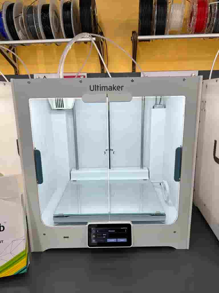
Ultimaker S5 printer
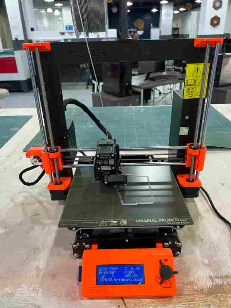
Prusa M3 printer
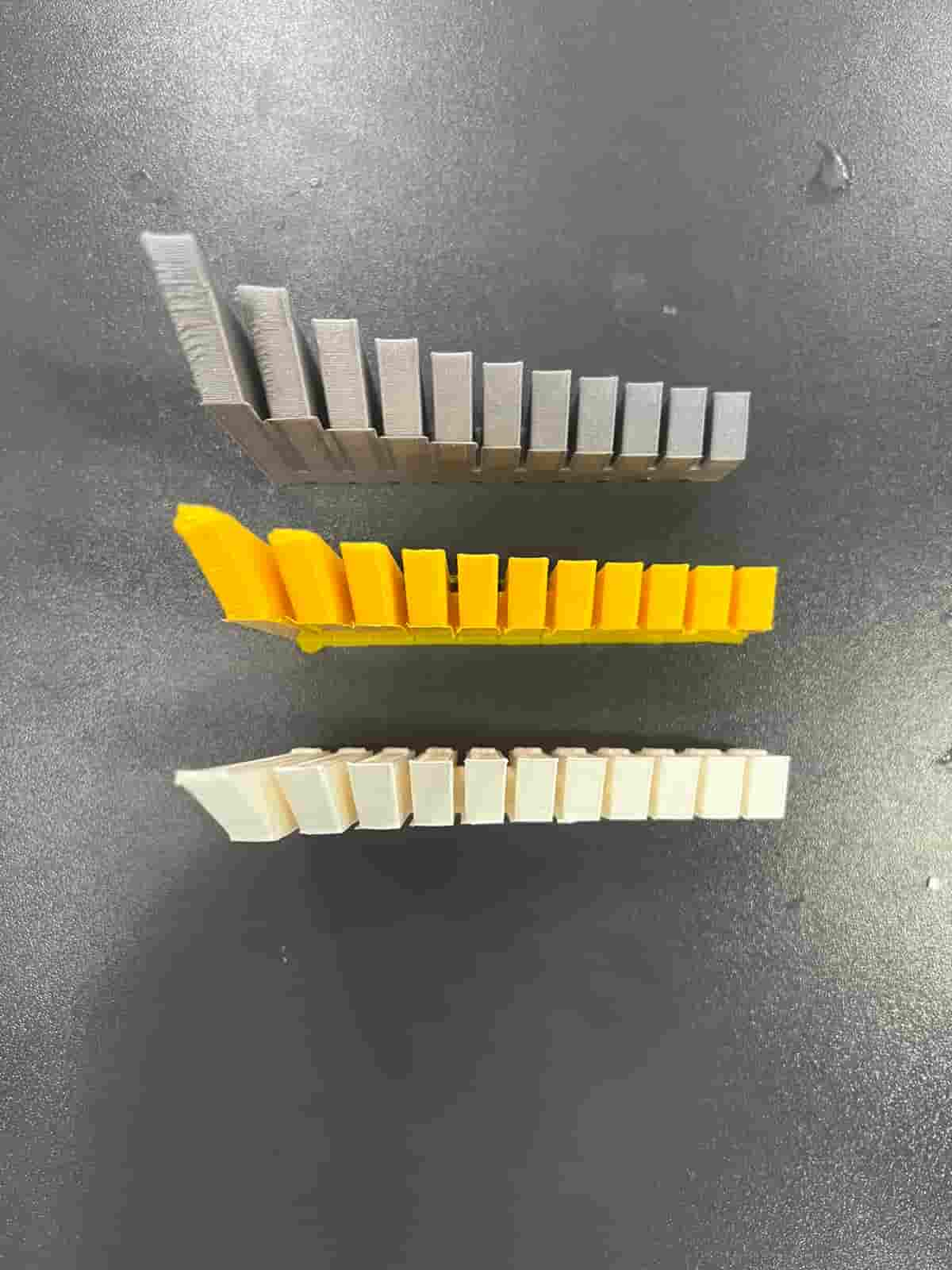
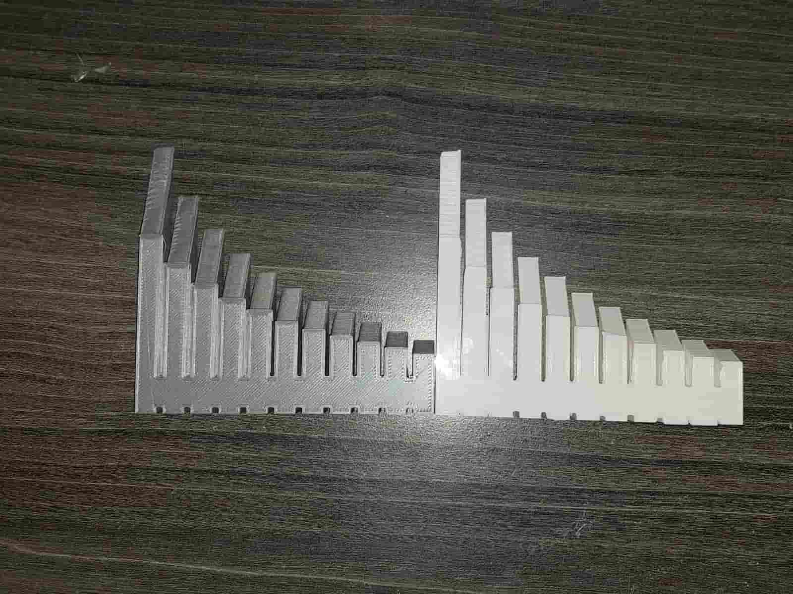
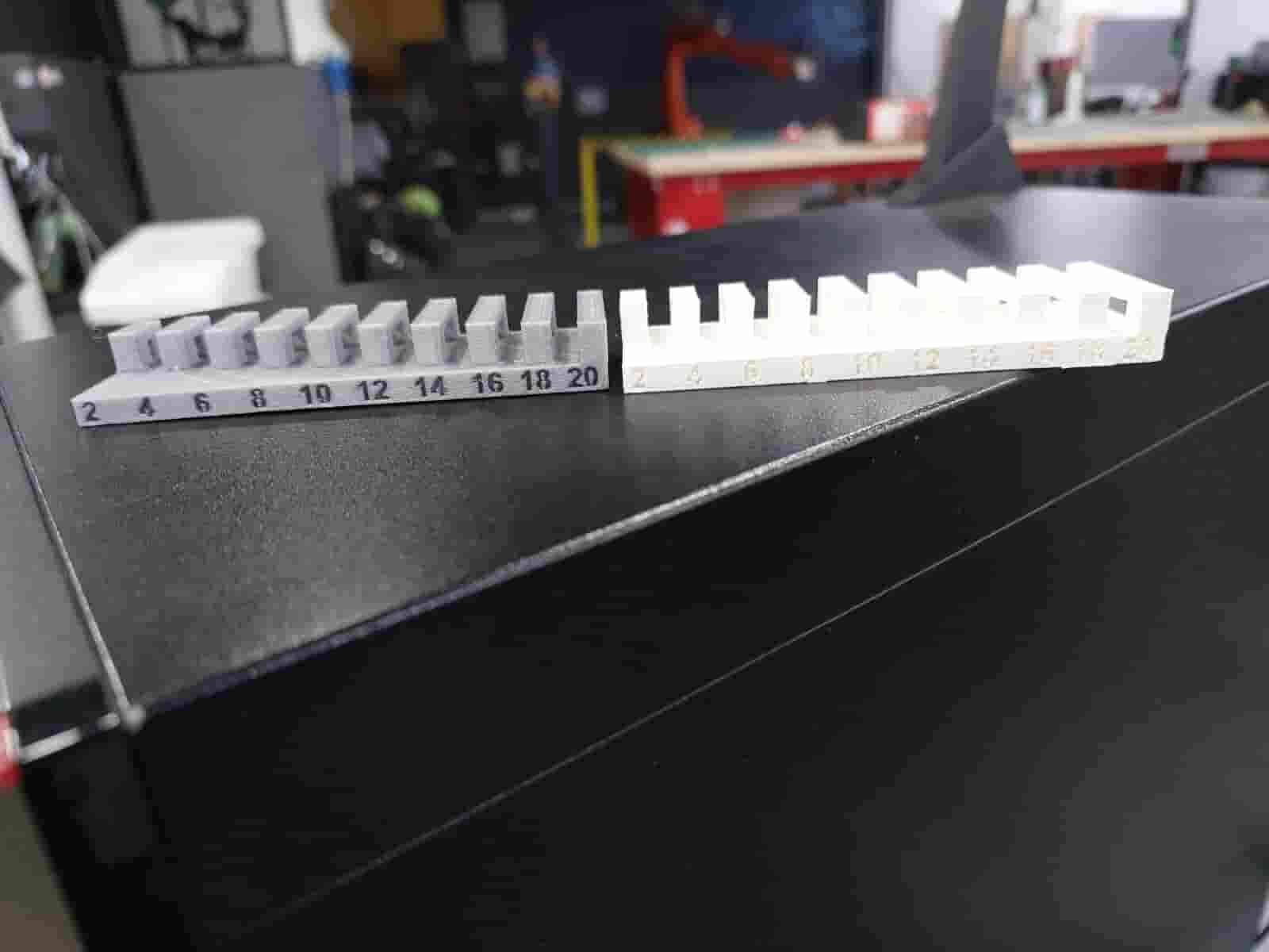
Angle test (white color for ultimaker ,gray color for prusa , yellow color for ultimaker with nozzle .8mm)
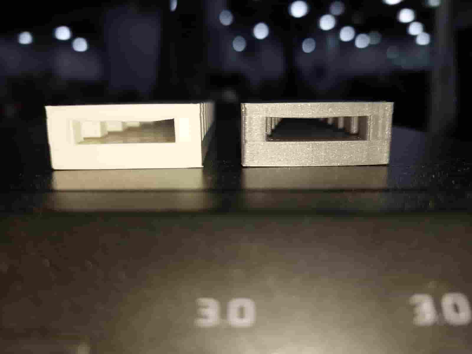
Bridging test (white color for ultimaker ,gray color for prusa )
Clearance test (yellow color for ultimaker ,yellow color for prusa )
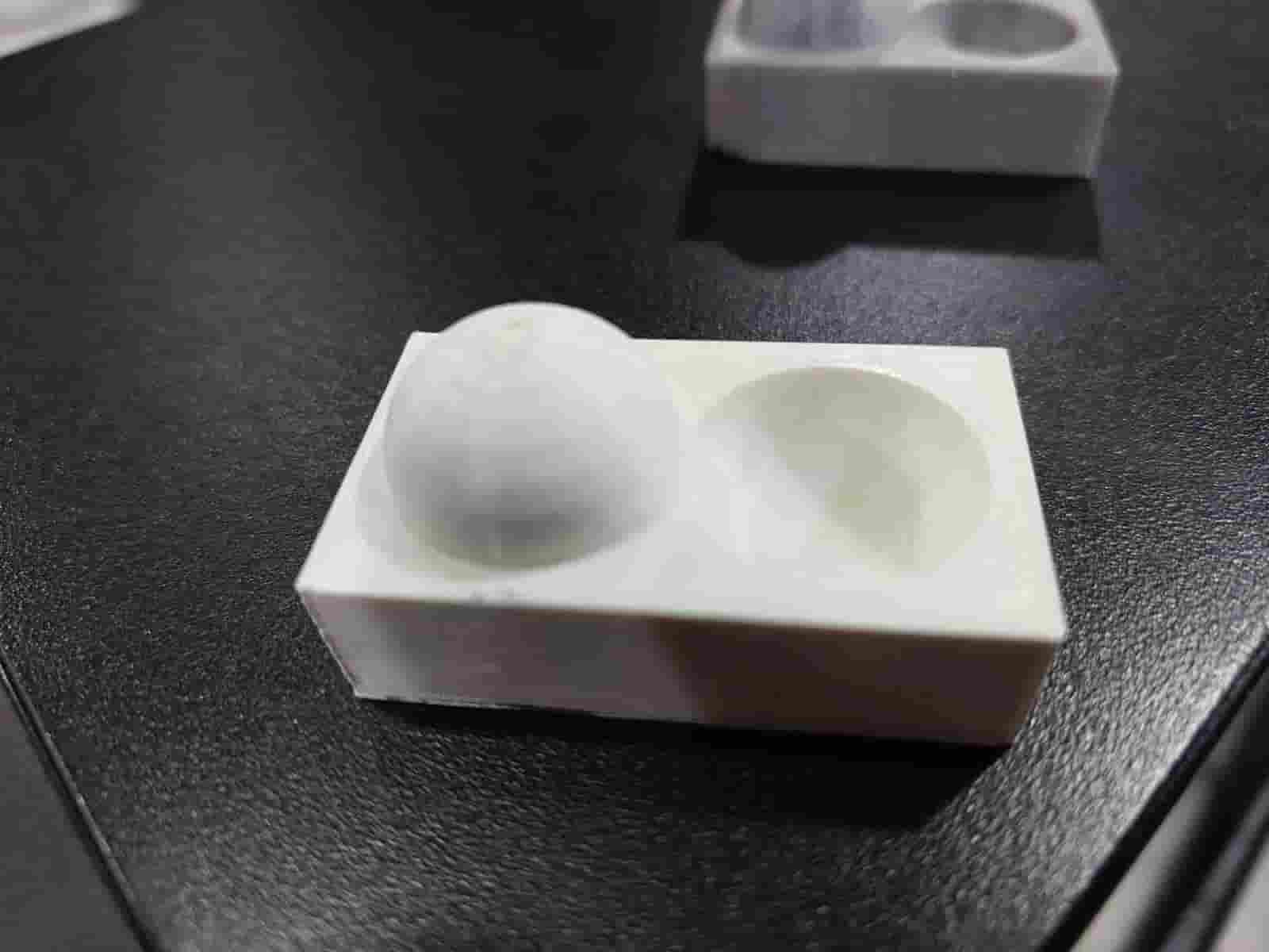
Finishing test for prusa for ultimaker
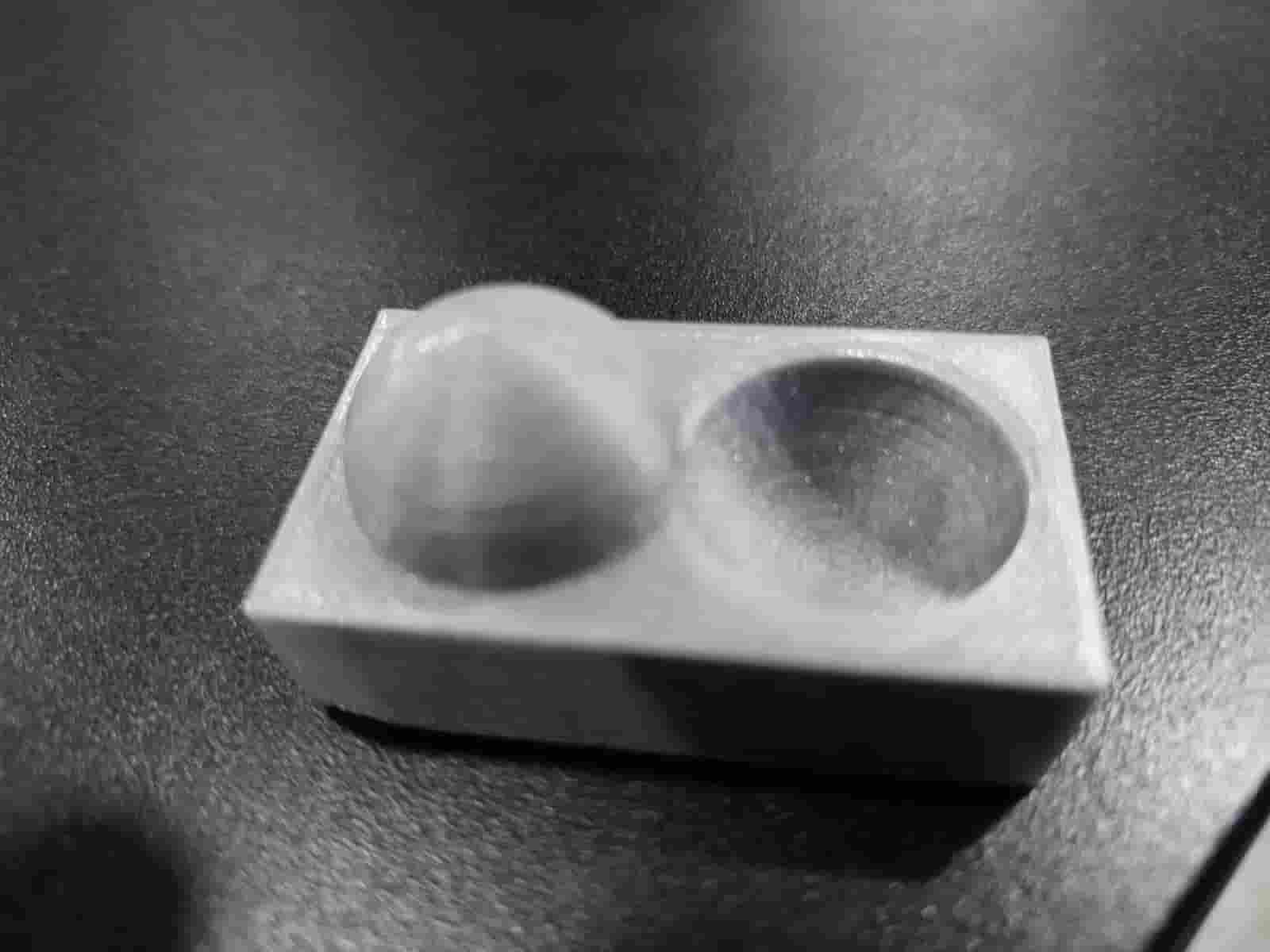
Finishing test for prusa
- Test 1 - Unsupported angles The Ultimaker show good quality at angles =< 65 Deg. Prusa show good quality at =< 60 deg
- Test 2 - Clearance: This test consists of a model test clearance between moving parts, For Ultimaker clearance is 2mm. For Prusa clearance is 3mm. ultimaker here is better
- Test 3 - bridging both printers show good quality at 180mm and below without any bellying surface.
- Test 4 - Surface Finish both printers showed good quality at 0.2 mm layer height.
Individual Assignment
In this week I take my idea by talking with chatGpt I tell him "I need a 3D design that could not be made subtractively just by using 3d printer"
he tell me about using soft material or make model with different material or with different color
then I ask him if model with meshes shapes can be used for that so he tell me about meshes and that can be an idea
so I search for that and I found a useful resource (XYZDIMS website)that use
openscad to model a (latice shape) named Triply Periodic Minimal Surface (TPMS) this shape is build using
trigonometry equation
so, I try to learn how to use openscad and I found a useful documentation at openscad website also
these are a very useful book you can see (Books) by that you can learn the basic and make your own model
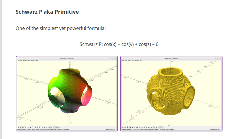
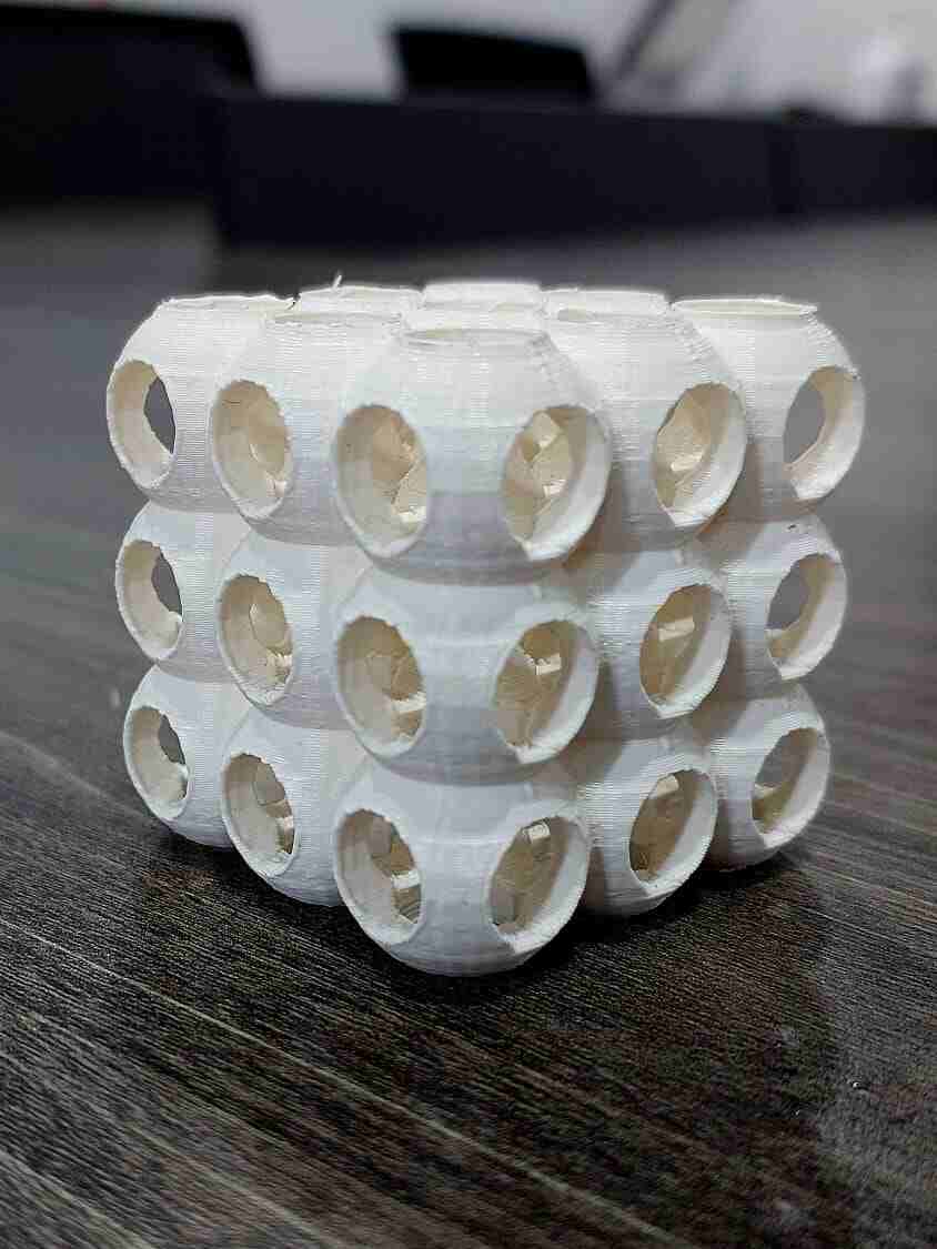
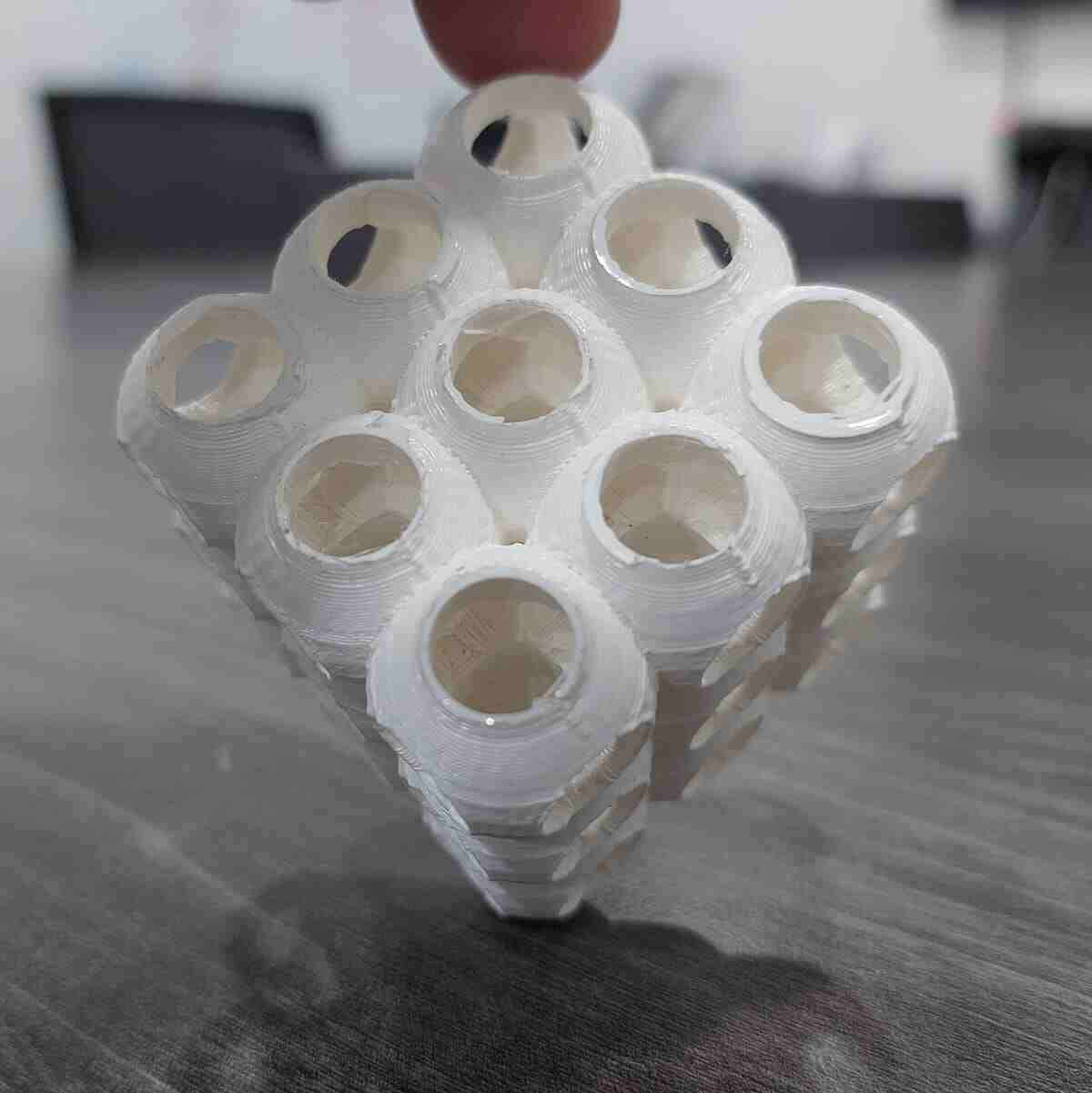
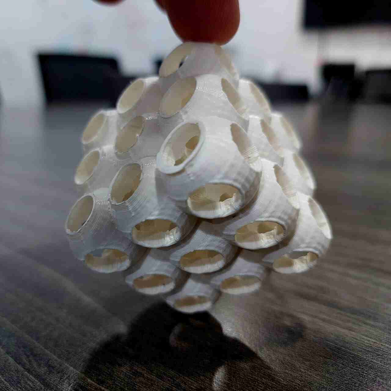
So, TPM surface can be build using trigonometry equation and then repeat the shape in pattern to make other shapes , for example the Schwarz P equation (cos(x) + cos(y) + cos(z) = 0) make a simple shape like a sphere with six hole
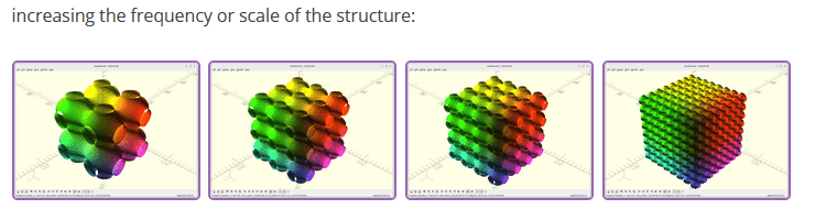
and by using openscad ' for loop syntax ' you can repeat this shape in any pattern you want
by that they have this result
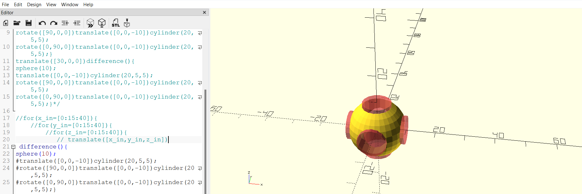
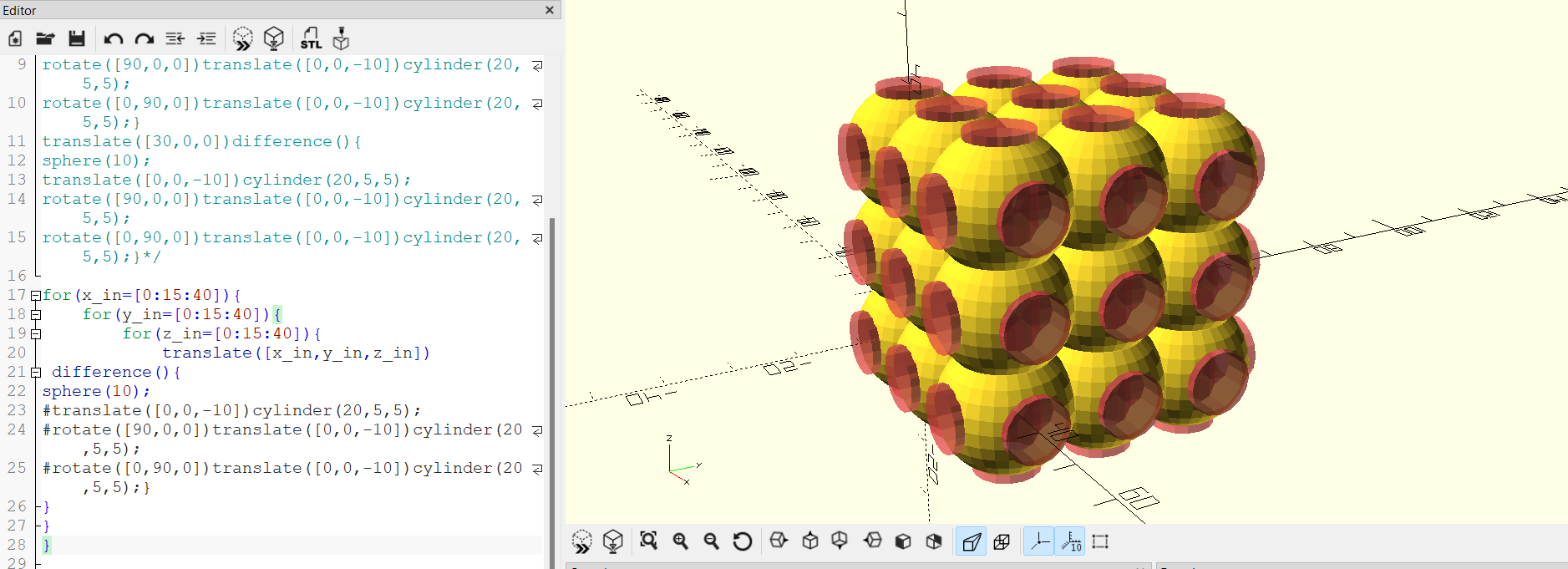
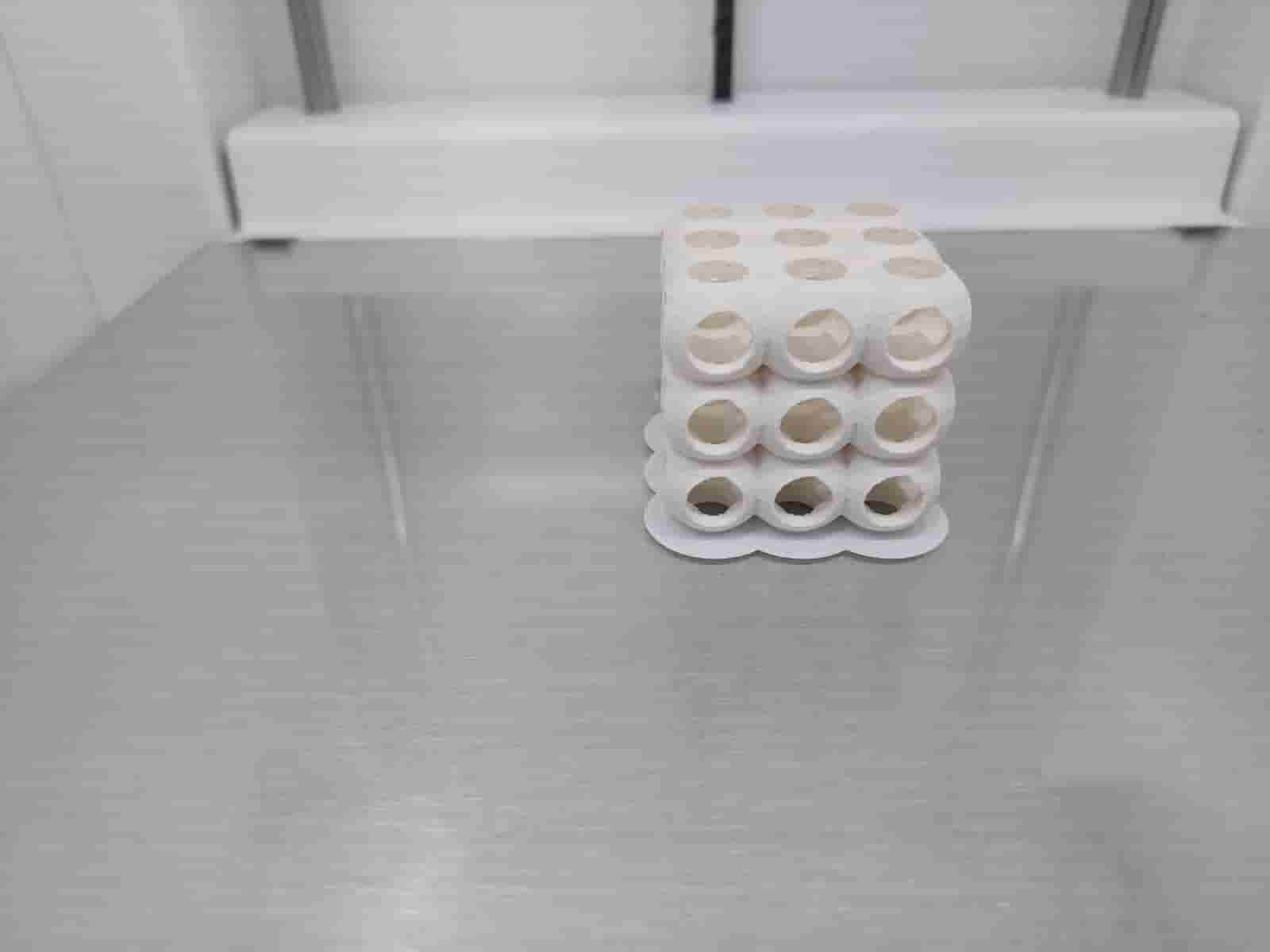
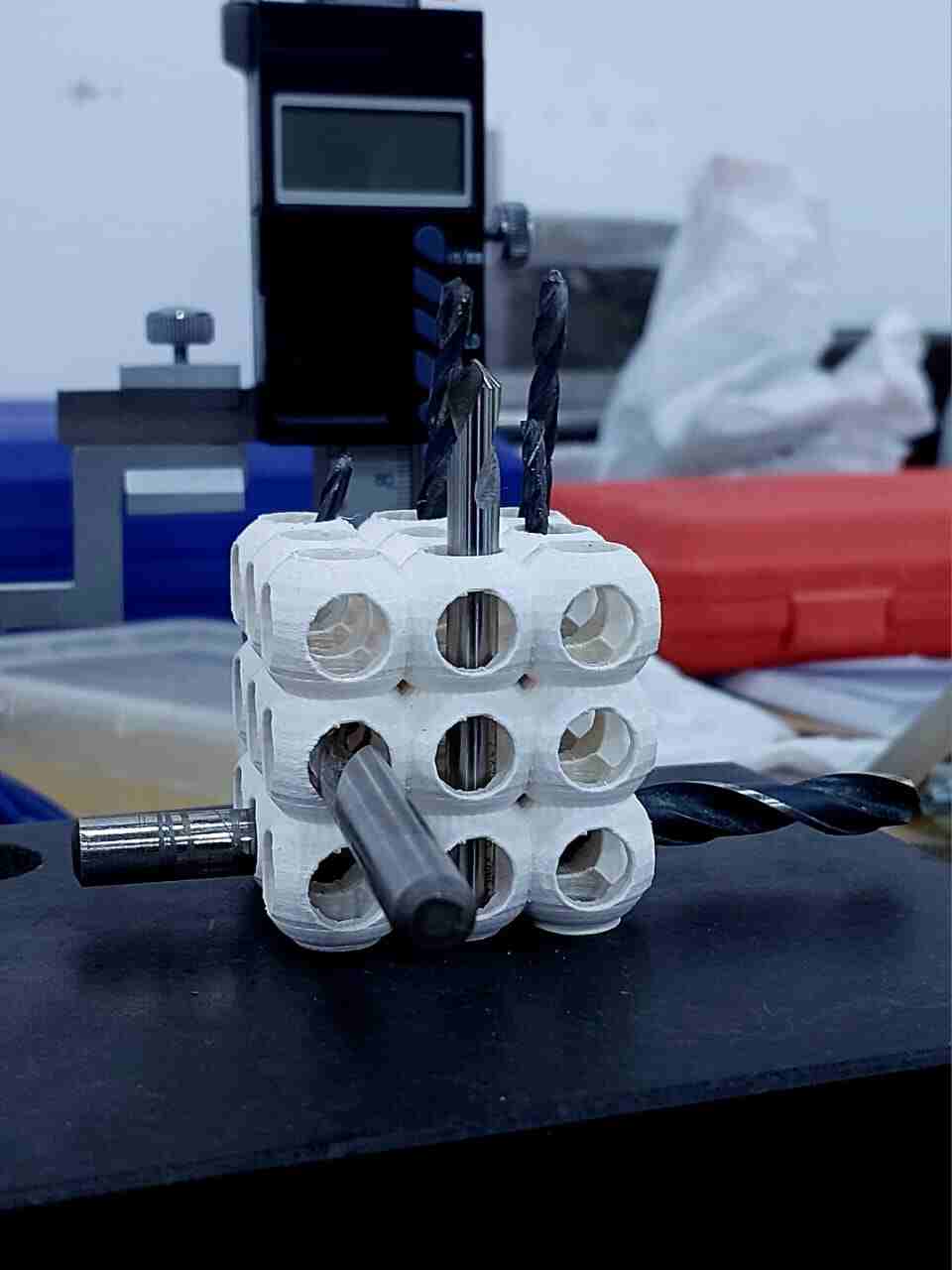
So, for me I try to use their code but when I render it it take a lot of time and it a little bet harder for my device when it comes to repetition process so , I just start to learn the basic of openscad coding to make my own shape ,so I make a sphere and cut three cylinder from it as a base block for my shape,"its look like openscad logo" then I repeat the shape using for loop to make it as a cube and this is my block and my final design result
lets print the model by this steps :
- Save model as STL file
- put it in cura slicer
-
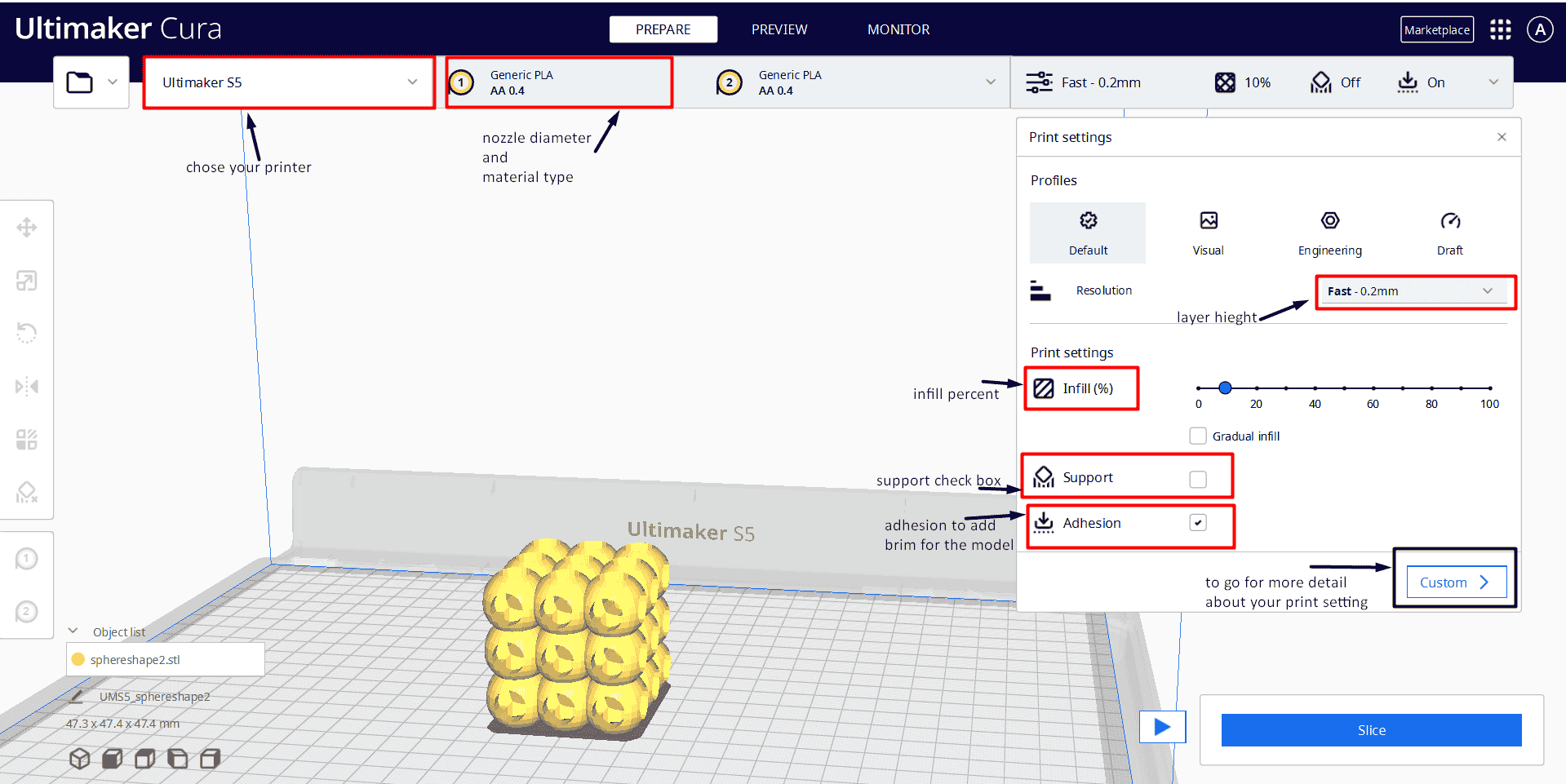
for cura setting
- chose the printer name
- chose the printer nozzle diameter and material
- chose the layer height
- chose infill percent , in custom setting you can chose the filling pattern
- check support box to add support for your model
- check adhesion box to make a brim around the model to stick it with your printer bed
- click on slice button,then you can print it by saving it to removable disk or via cloud network
for me I use Ultimaker S5 printer ,in cura I put the infill setting 10% percent and the infill shape as concentric , for support I didn't use any support for my model , for the layer hight I put it .2 mm with .4 nozzle diameter
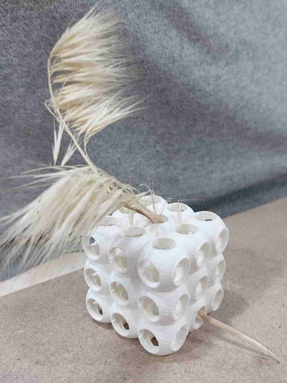
here's my colleges start to think how to use the model ,one of them try to put plant inside it it look really nice, others try to use it as a bits organizer or as pencils organizer
in this video you will see the workflow to use the 3D printer
summaries the printer work flow
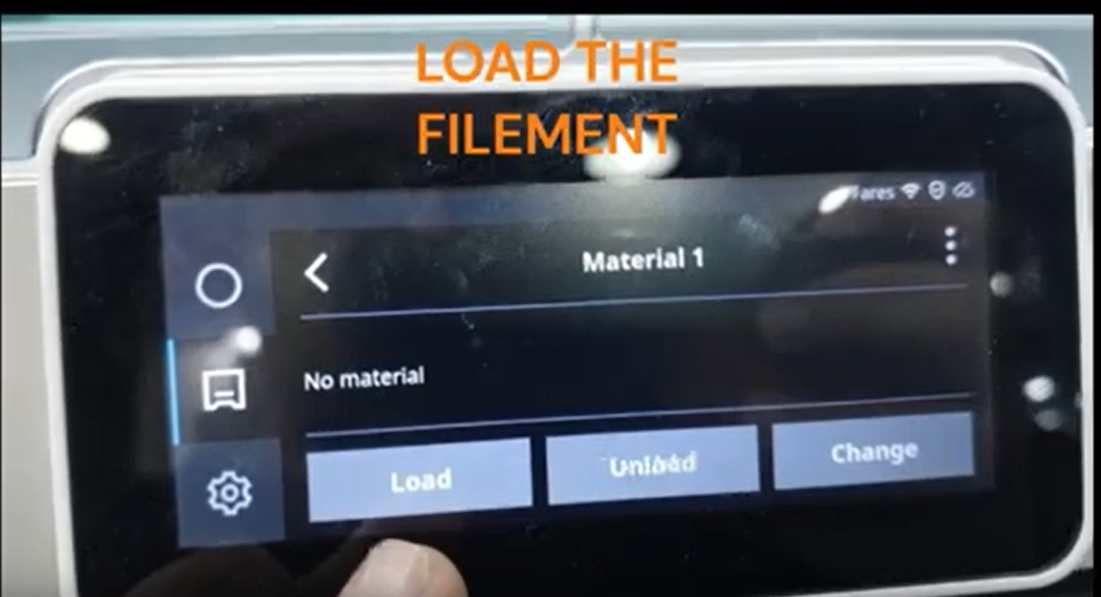
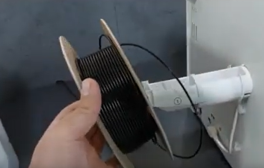
Step 1: Add Filament
To begin, load the filament into the 3D printer. Insert one end of the filament into the filament guide tube or feeder mechanism, and feed it through until it reaches the hot end of the printer.
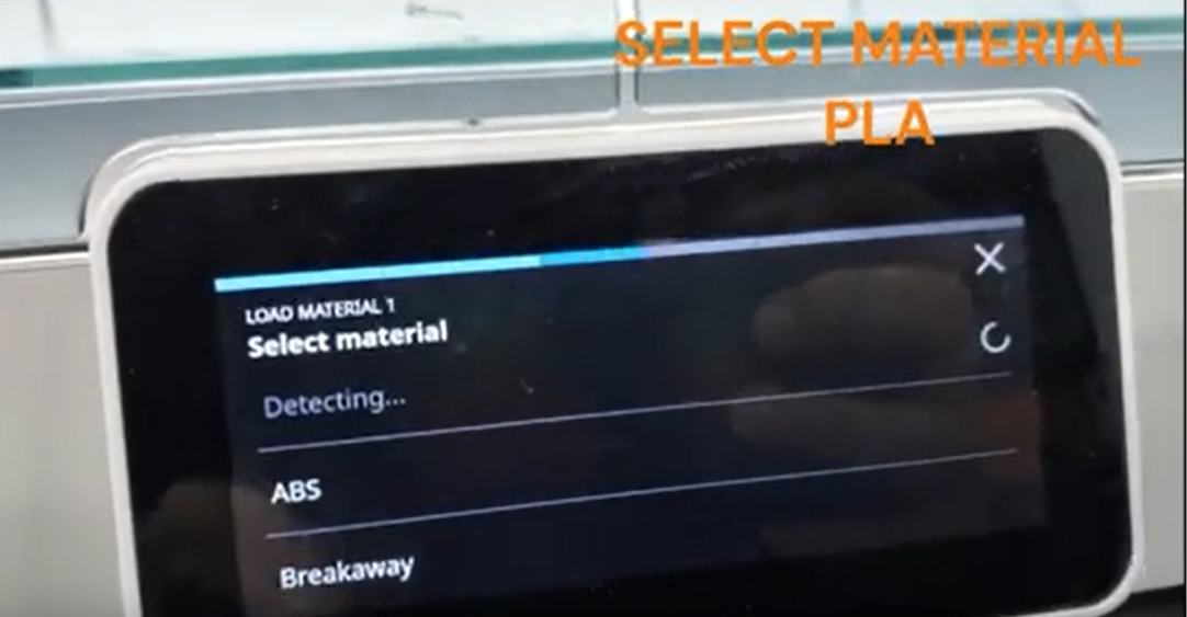
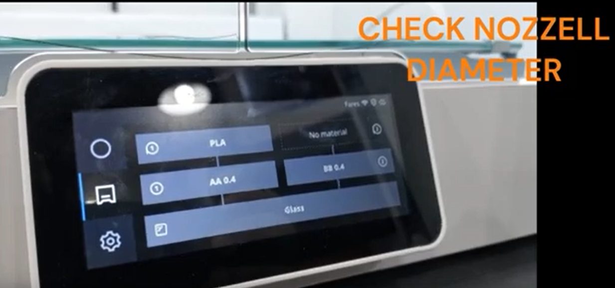
Step 2: Set Material Type
Next, set the material type on the 3D printer. This ensures that the printer's settings and temperature are optimized for the specific material being used. Common material types include PLA, ABS, PETG, and more.
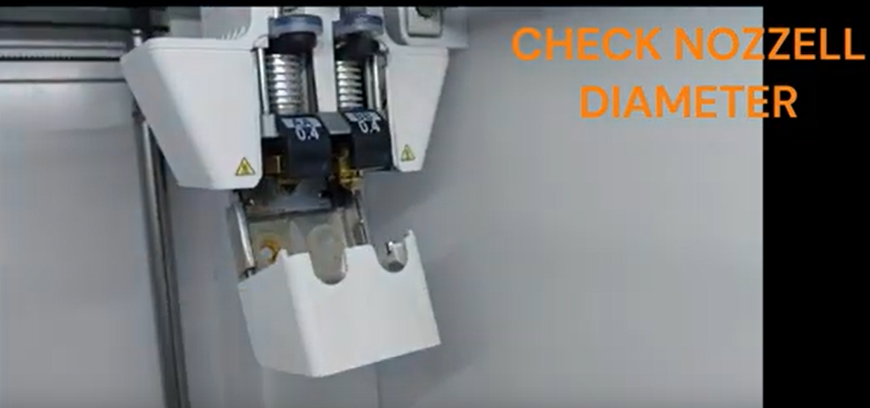
Step 3: Check Nozzle Diameter
Check the nozzle diameter in the printer. The nozzle diameter affects the precision and speed of the printing process. Ensure that the correct nozzle size is installed or make any necessary adjustments.
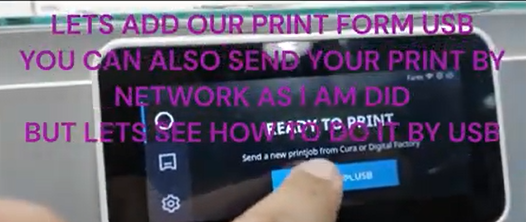
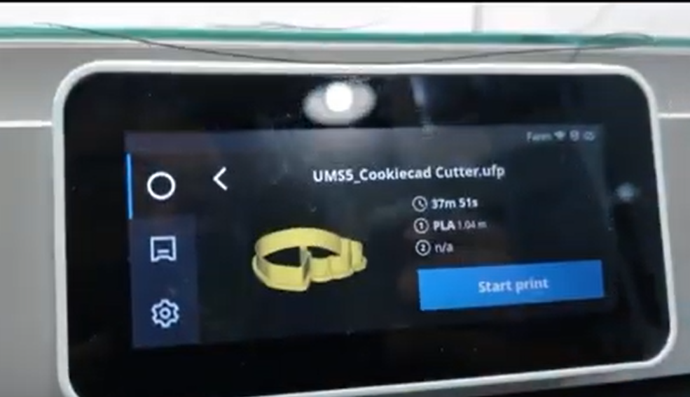
Step 4: Select Printing Part
Choose the specific part or object you want to print. This can be done by either selecting it from the usb or sending the model through network
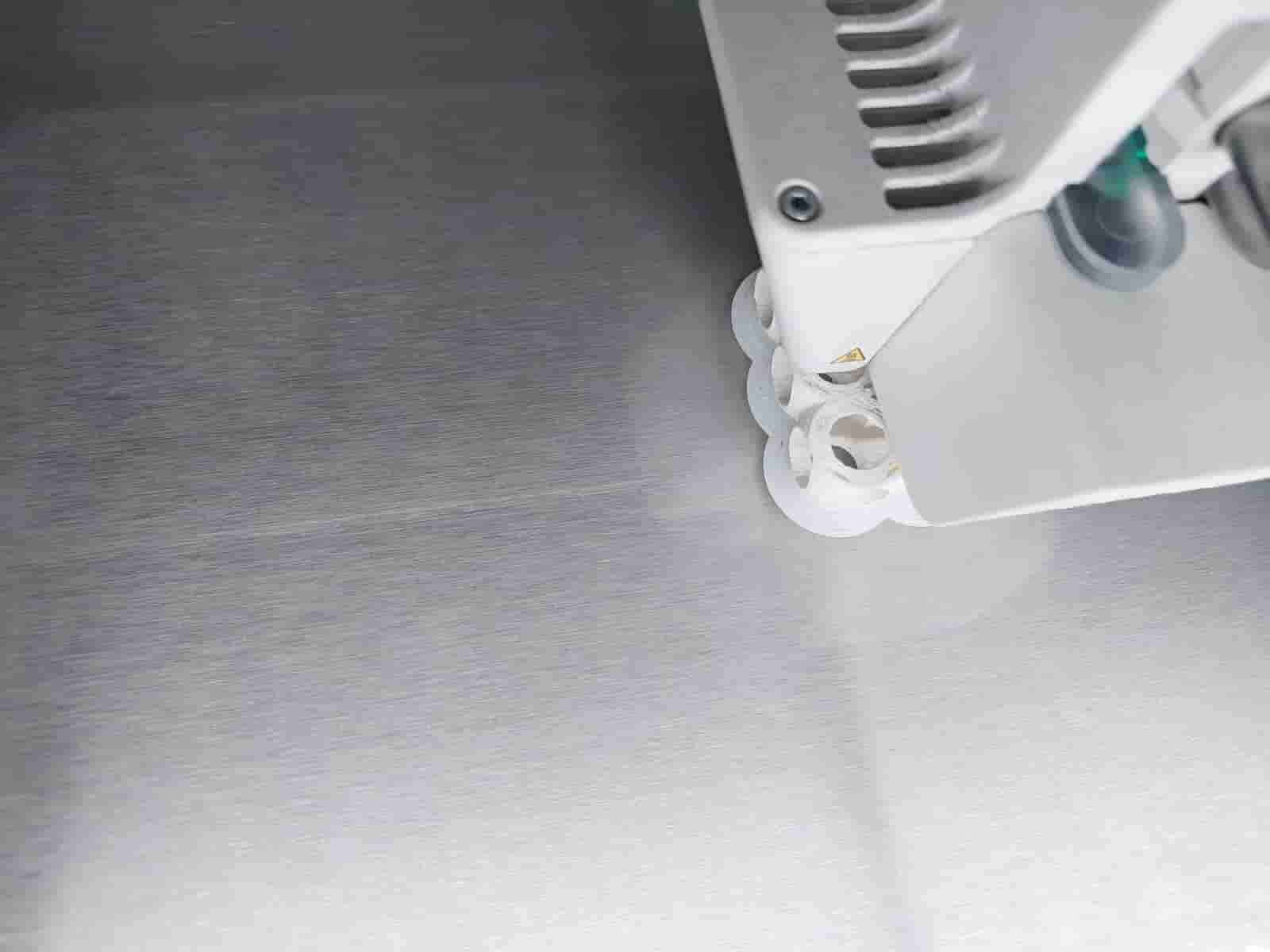
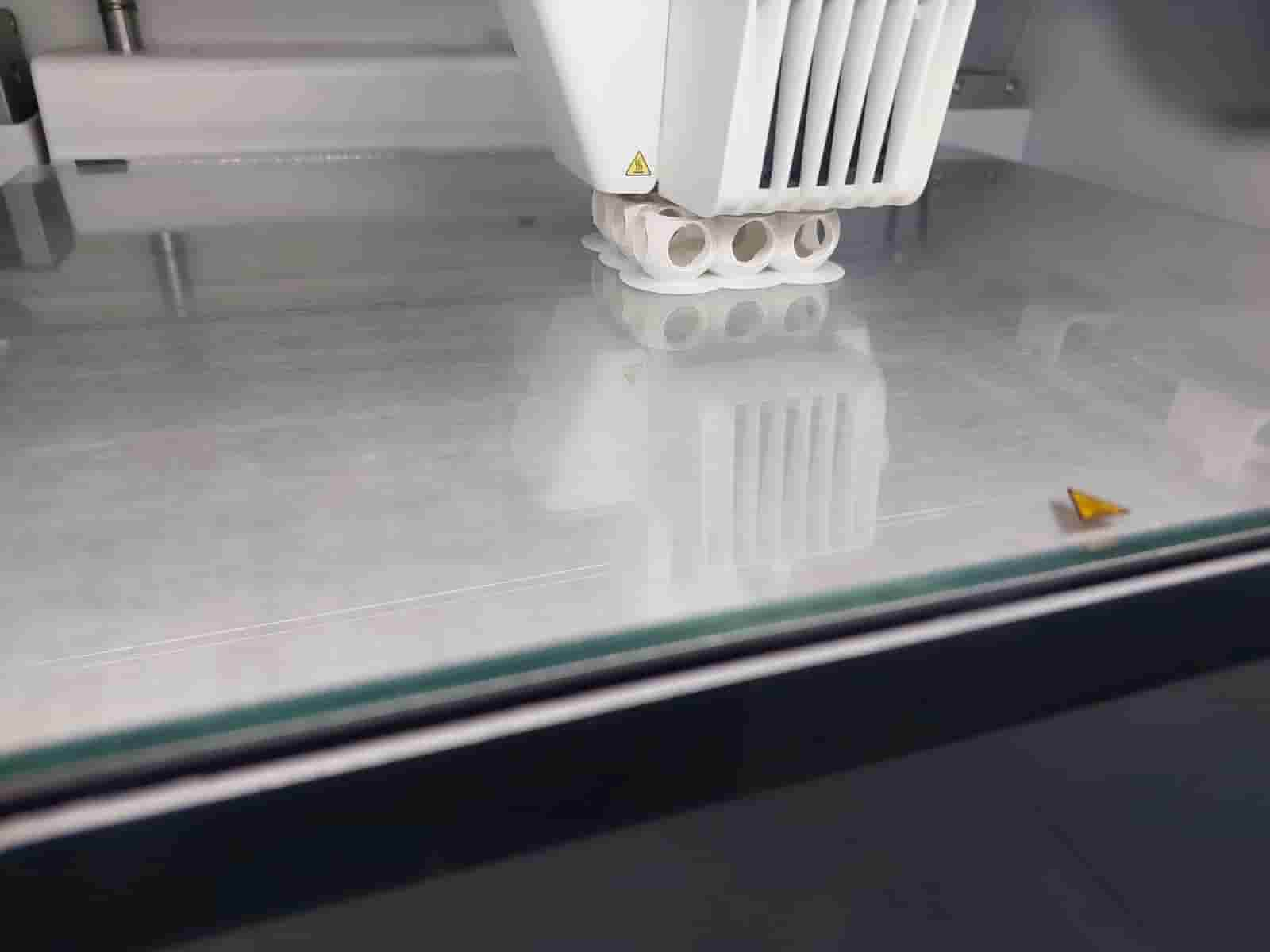
Step 5: Monitor the First Layer
The first layer is crucial for the success of the print. Keep a close eye on the printer as it begins printing the first layer. Ensure that the filament adheres properly to the build plate and that the layer is smooth and evenly printed.
Once the first layer is successfully printed, the 3D printer will continue with the rest of the layers to complete the object.
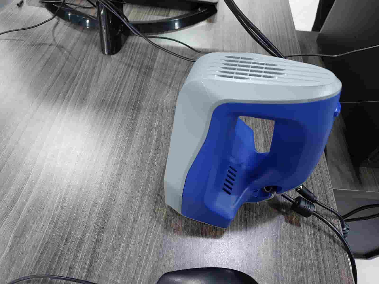
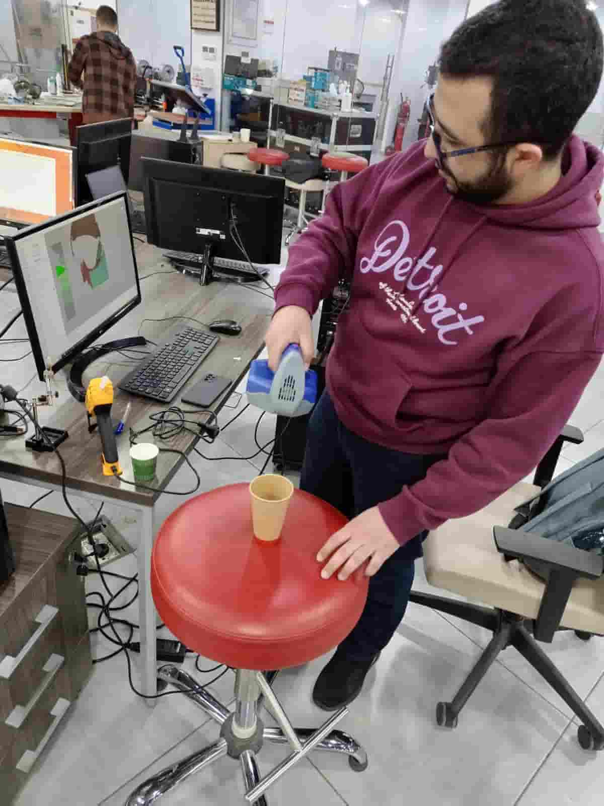
3D scanning
In 3d scanning I use Artec Space Spider scanner it's a power full tool for making a digital 3d model for your 3d model its software is easy to learn and give you a lot of tool so, my 3d model is a cartoon cub ,Before going to the steps i follow ,an important note that In scanning all the magic happen almost in the software that is used ,spider scanner used Artec Studio 17 its so helpful software with a lot of features and tools , you can read more about it here ,so my process for scanning start as follow
- open Artec Studio 17 software
- Take different scan of your model from different angle to cover all the faces of your model
- Edit each scan by removing anythings appear not related to your model
- You can align the scans by yourself or let the software do that for you
-
press autopilot tool after you chose the scans you want to make the software start it's magic and create your model
- it will ask you some sitting related to model texture and it accuracy (I chose the default setting)
- it will ask you then if you want to edit on your scans and remove any bugs in your scans
- then ask you if you want to align it automatically or manually (For me I chose auto mode)
- then it will start to do it works and combine the scans and make your final model
spider scanner
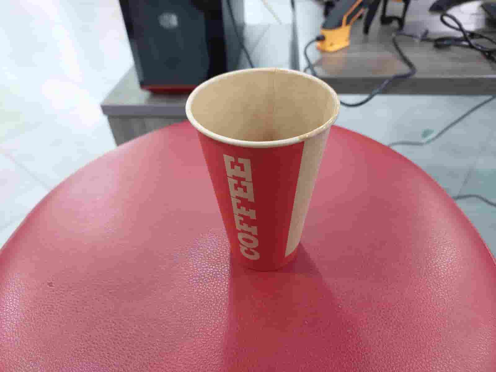
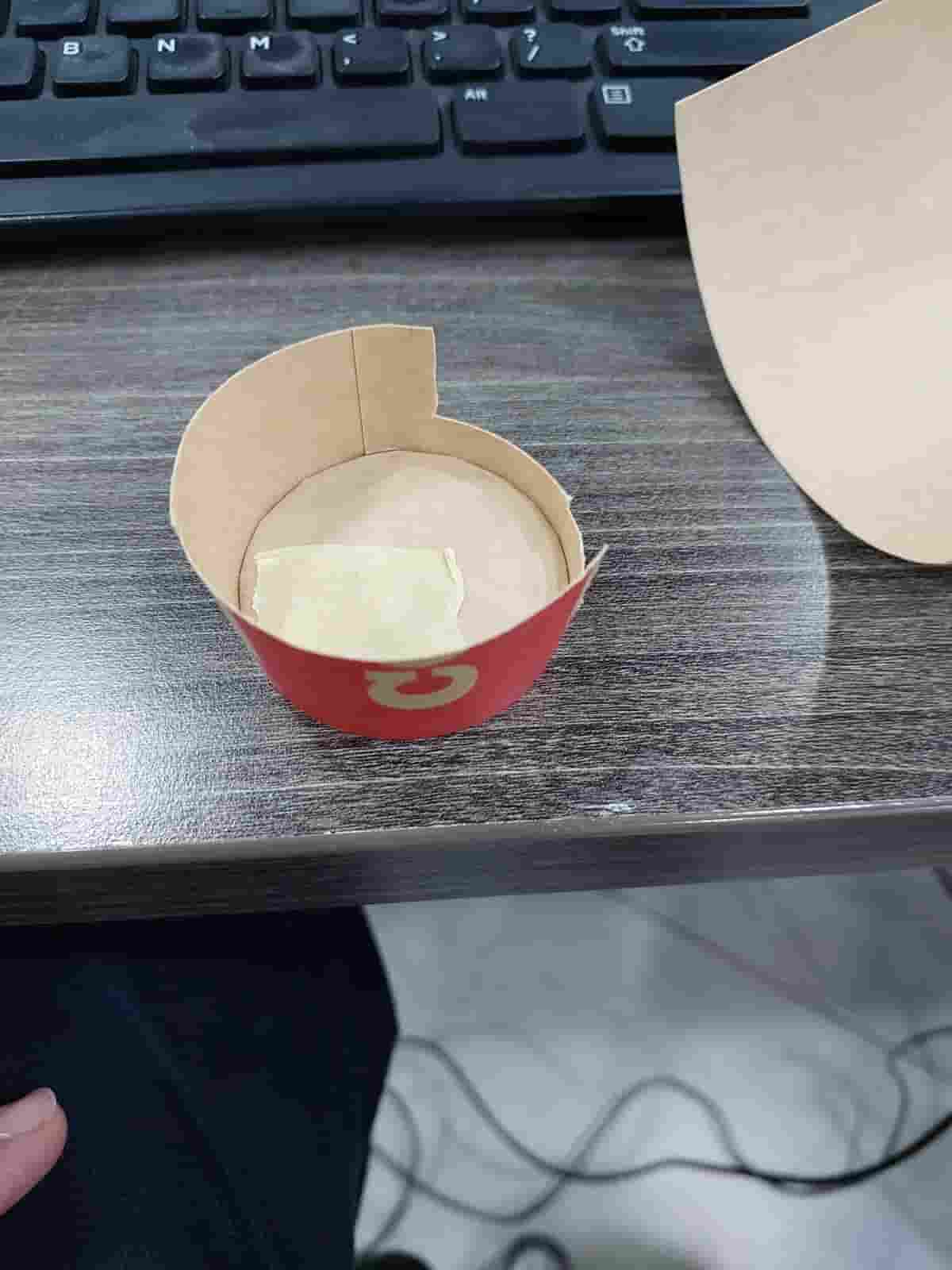
carton cup
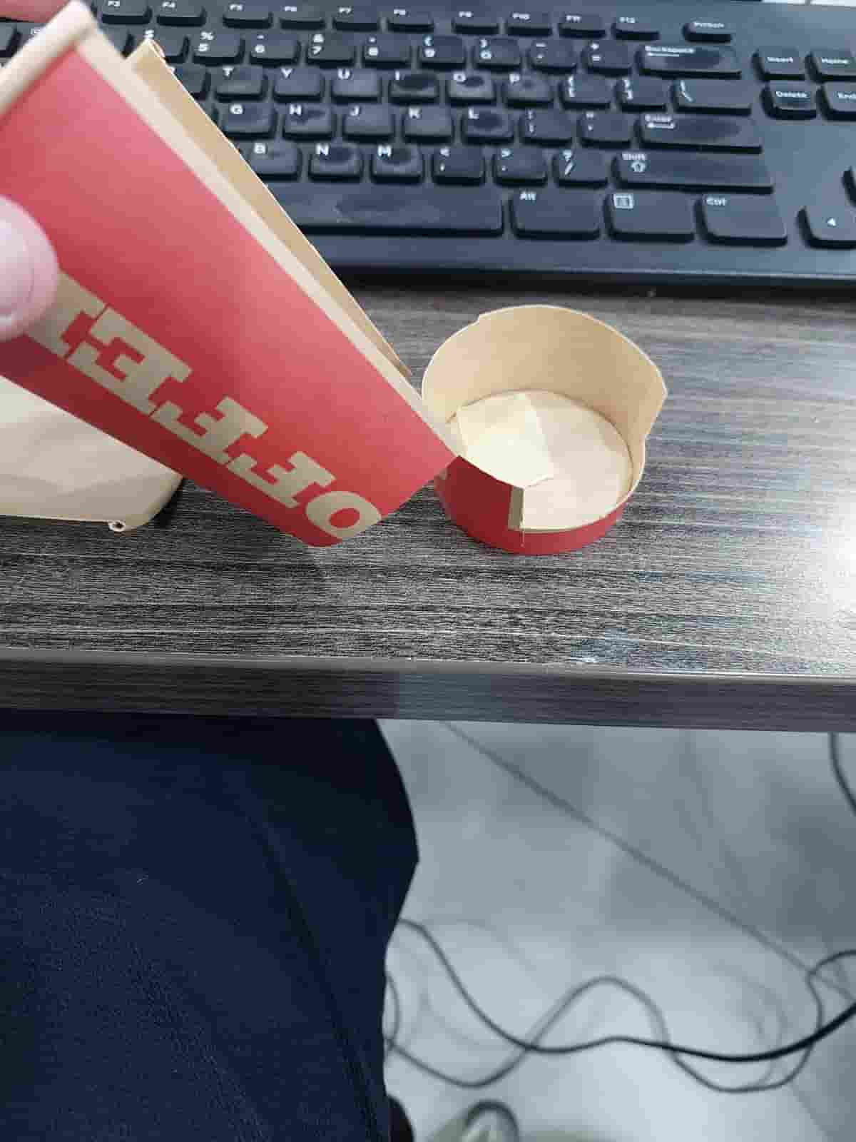
I cut its outer surface to detect the inner surface and it's base
start autopilot mode to combine the scans,chose the scans that you want to combine them
.jpg)
chose the scan quality (more quality mean more time to process) I cj=hose good quality
.jpg)
Now the software ask you to make a manual edit for the scan that you make ,by remove any excess part
.jpg)
there are many method to select the excess part, I used the lasso selection tool to select the part I don't need then I press delete
.jpg)
.jpg)
here the software ask you if you want to make the alignment of your scan manually or automatically , I chose the automatic method
.jpg)
.jpg)
after finishing the alignment it ask you it check if the alignment is good , I press yes then next the combining process start
.jpg)
the model is ready
.jpg)
final model
What I learn to have a good scan you should follow those steps :
- you need to take a good scans from different view
- add a marks (by sticker or marker) to help the scanner when it come to combine processing
- you should look to the computer screen when you start scanning to see the distance of your hand and try to adjust it in proper way
- clean each scan one by one to make your work flow faster
- you need to be patient to have a good scan