Week 7: Computer-Controlled Machining
Group Assignments:
1. Safety
So, The safety rule for using a CNC router machine come as below :
Always wear appropriate personal protective equipment (PPE), including eye and ear protection, gloves (just when you change the tool),
and proper clothing, when operating a CNC router machine. The machine generates a lot of noise and debris that can be harmful to your eyes and skin,
and the cutting tools can cause injury if not handled properly.Additionally, be sure to tie back long hair and remove any loose
jewelry or clothing that could get caught in the machine.
Following proper PPE guidelines can help prevent accidents and injuries.
Also,it's important to receive proper training on how to use the equipment and to never operate it if you are unsure of how to use it safely. Always be aware of your surroundings and keep a safe distance from the machine when it is in operation. It's also important to perform regular maintenance on the equipment to ensure it is in good working order and to report any defects or malfunctions to a supervisor. Following these safety rules can help minimize the risk of accidents and ensure a safe work environment.
.jpg)
Tooling and machine
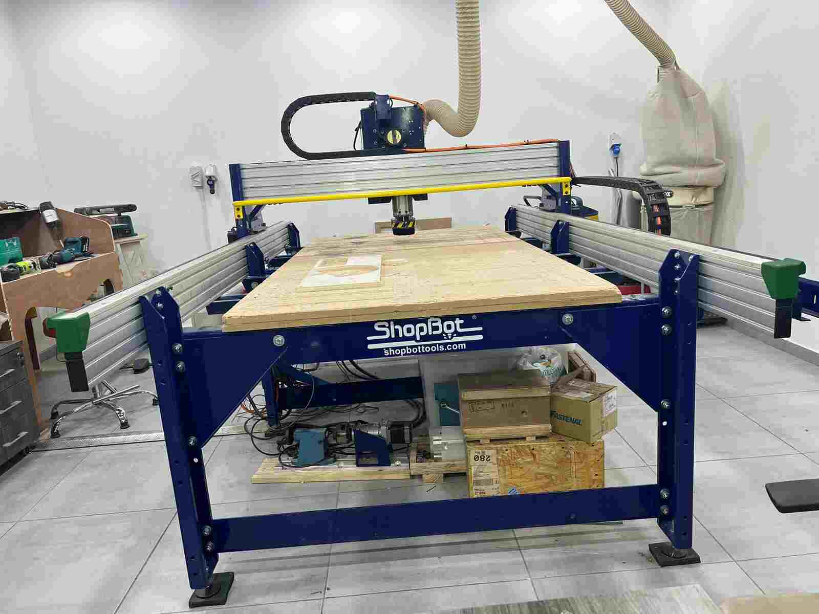
We worked with ShopBot PRSalpha ATC 96-60-8 CNC Machine. It's an affordable full-sized gantry tool for CNC cutting, drilling, carving and machining of wood, plastic, aluminum and other materials. It has a bed of size 2440mm x 1220mm and has a rapid transit speeds of 1800 inches per minute and cutting speeds of up to 600 inches per minute.
Tooling
Roughly, an endmill is characterized by:
its type/geometry, which relates to its intended use:
- square endmills are used for cutting flat surfaces e.g., pocketing and contouring, and for removing
material quickly (roughing).
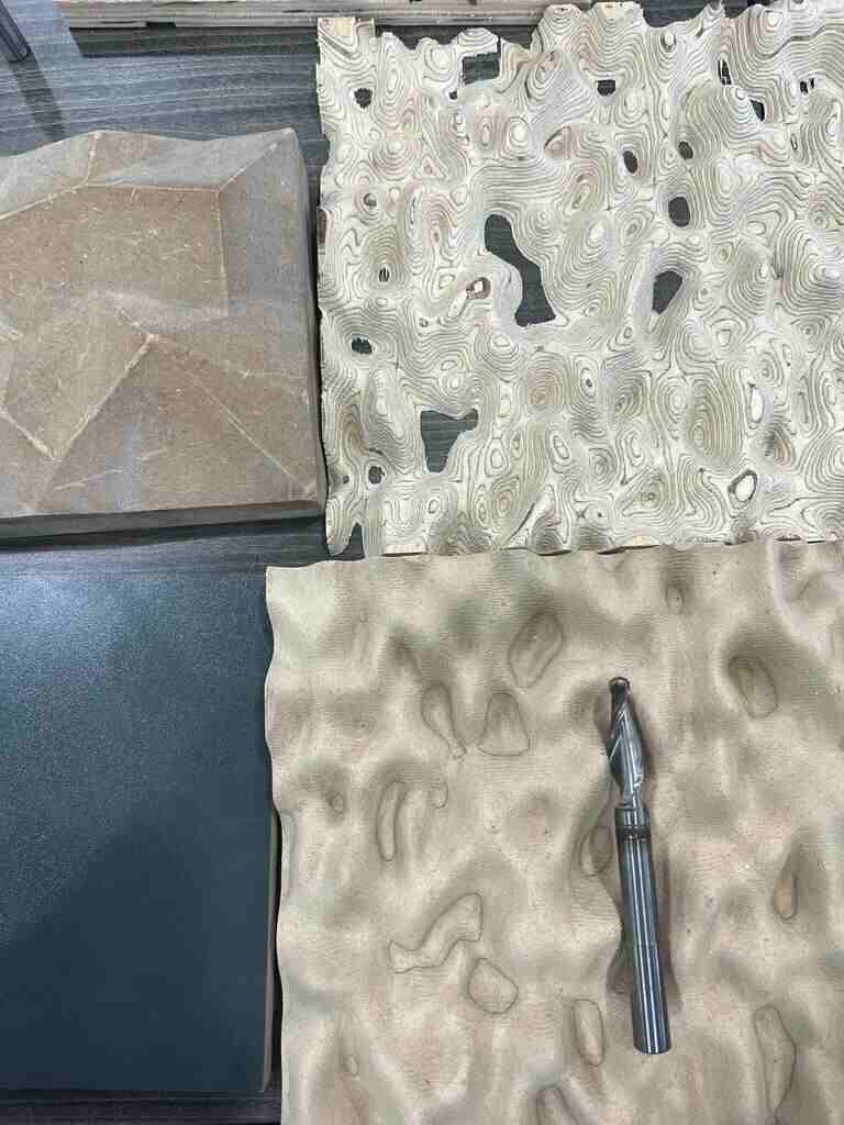
- ballnose endmills are typically used for milling 3D surfaces.
- V-bits are used to carve variable-depth grooves based on a 2D feature.
the diameter of its shank (the part that goes in the collet/tool holder)
- a large shank is better for reducing deflection.
- the choice of shank diameter is constrained by the available collets.
the diameter of its cutting part
- the smallest feature size in a design determines the smallest endmill diameter needed.
- smaller endmills are more fragile and more sensitive to runout (more on this below).
the length of its cutting part (Length of cut / LOC), and its overall length (OAL).
- a short LOC is better for stiffness, but obviously constrains the max depth of cut.
- a long OAL provides better reach, at the expense of rigidity/deflection.
- On the smallest diameter endmills, the cutting length is really short otherwise the tool would be
extremely fragile and deflect too much
the number of flutes (number of cutting teeth):
- fewer flutes are better for chip evacuation.
- more flutes are better for stiffness and finish.
the material it is made of:
- carbide is king these days for CNC milling, but it is brittle.
- high speed steel (HSS) is cheaper and tougher, but more limited in speeds.
its coating, if any:
- Generally, no coating is needed for cutting wood and plastics.
- ZrN (Zirconium Nitride) coating is good for non-ferrous metals e.g., aluminium, brass, copper,
titanium.
- AlTiN (Aluminium Titanium Nitride) coating is good for steel/ferrous-metals.
whether it is center cutting or not:
- most are, it means they have the ability to plunge into the material (vertically), like a drill bit does.
- non-center cutting tools are more commonly used on manual power tools, think router bits.
Different type of endmill

Ballnose endmil for 3d shape
Feed rate and speed
"Feeds" is feedrate, on some CNCs with a fixed tool and moving plate this is the speed at which the
material is fed into the cutter, on a Shapeoko this is the speed of the gantry pushing the cutter into the
material.
"Speeds" is the rotation speed of the endmill, i.e. RPM value
So,to calculate the feed rate we follow this equation :

Chip Load or Feed Per Tooth: is the theoretical length of material that is fed into each cutting edge as it moves through the work material.Chip Load given by tool manufacturers is the distance the material is moved into the cutter at the centerline of the tool as each cutting edge rotates through to cut.
rpm:rotation speed of the endmill revolution per minute
Nb_flute:number of flutes (number of cutting edges)
for chip load there is a manufacturing table that give you the range of acceptable value for different type of material

After completing the safety training and familiarizing ourselves with the tools and machinery, we put our knowledge to the test.
First, we practiced fixing a wood board onto the sacrifice bed using screws.
Next, we performed a cutting operation and checked the alignment, which was accurately set to a sharp 90-degree angle on the corners.
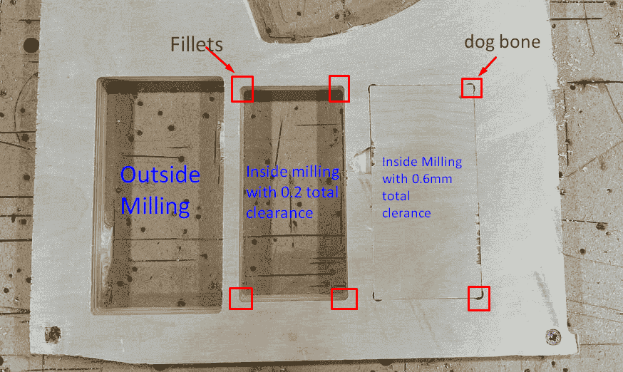
To test the clearance, we tried the following techniques:
-Using outside milling, we obtained a rectangle with precise dimensions matching the design.
-With inside milling and a 0.1mm clearance, the corners had a fillet, which was equal to the radius of the tool. Therefore, we were unable to fit the rectangle we obtained from the outside milling operation.
-Finally, we used inside milling with a 0.6mm clearance on each side, with 0.6mm in height and width, along with a dog bone technique. This allowed us to create a rectangle that we could fit into. Please refer to the image for a better understanding of the process.
Individual Assignment
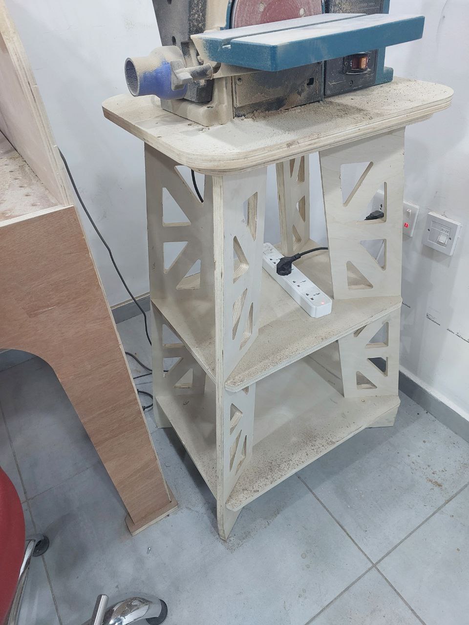
I created a table for the wood carving machine in our lab using Fusion 360. The design consists of two components: shelves and legs, which are connected using a press and fit method. Each leg and shelf has a slot that enables them to be connected with each other.
For CAD (Computer-Aided Design), we use Fusion 360, and for CAM (Computer-Aided Manufacturing), we use V-Carve. To create a design in V-Carve, we need to provide a vector file in formats such as DXF or SVG.
To convert a 3D model to a 2D design, we start by opening the model in Fusion 360. We then select the necessary components and place them on a 2D plane. Once we're satisfied with their placement, we press the "P" key to create a projection 2D design. We then choose the surface we want to work with and click "OK."
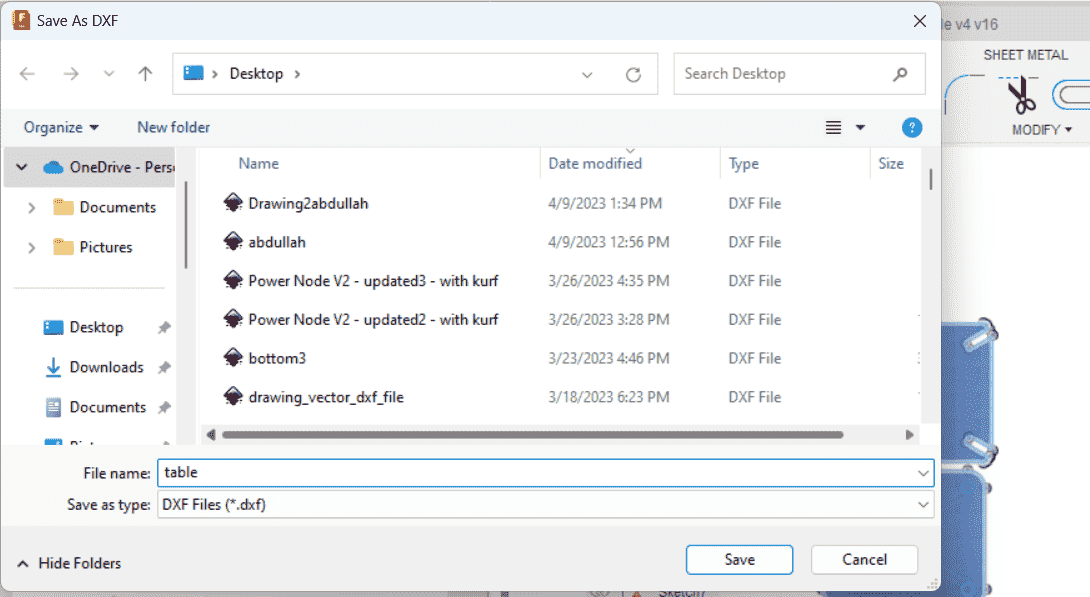
To save the design as a DXF file, we navigate to the tree history in the Sketch section of Fusion 360. We right-click on the sketch we want to save and select "Save as DXF." This will convert the 2D projection design into a DXF file that we can use in V-Carve for further CAM operations.
,to make the process more clear you can see those screenshot
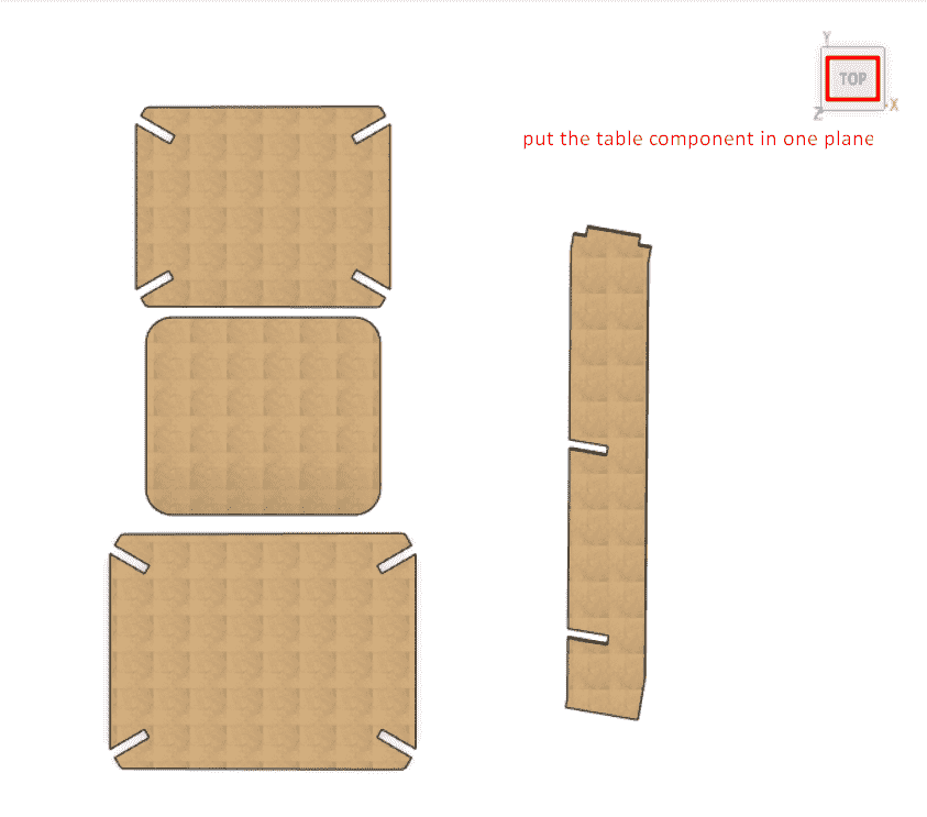
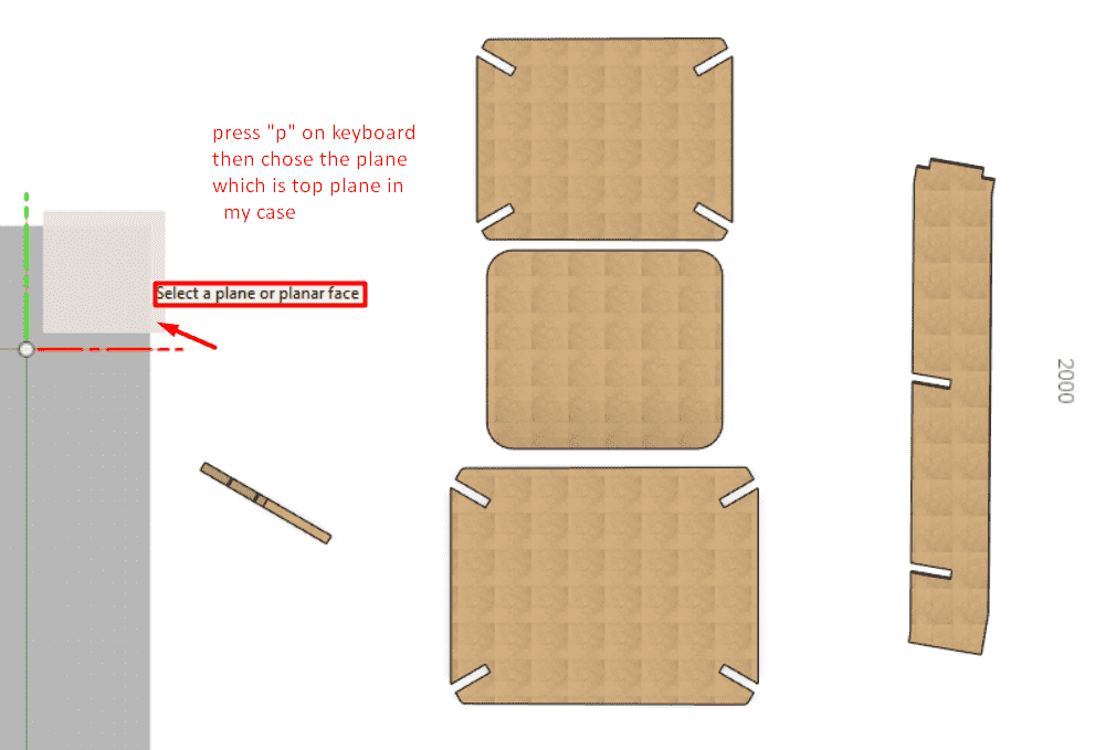
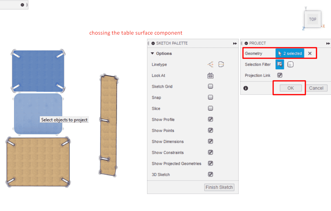
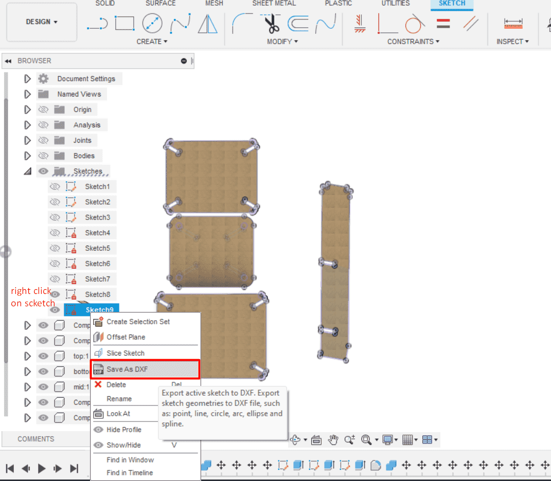
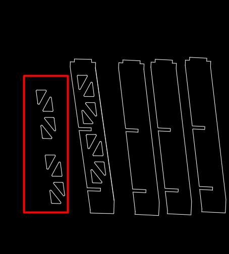
for me I make a little modification on 2d design using AUTOCADE in order to add the leg shape pattern it was easy to make the pattern in quick and precision way ,
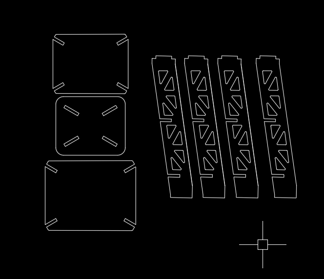
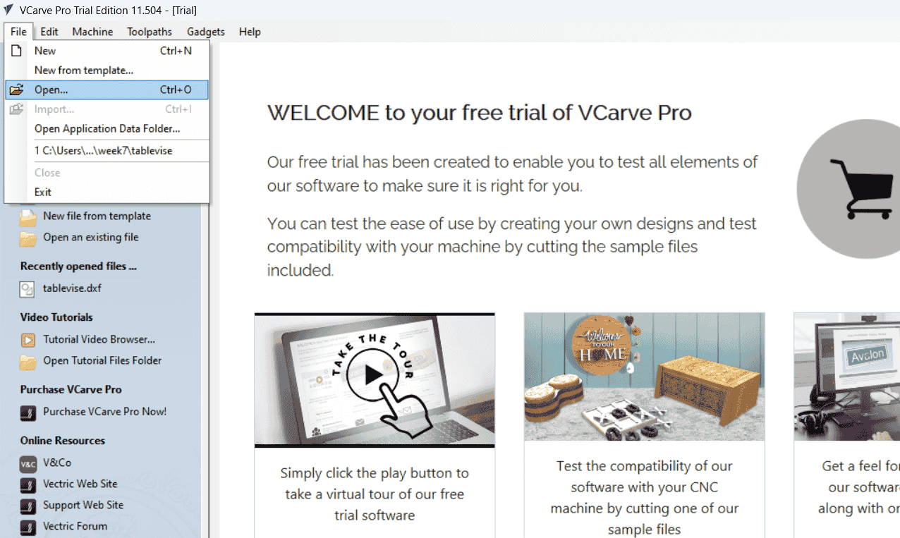
lets go now to v_carve the cam part , first of all I open the dxf file in v_carve ,then adding the wood board properties like height , width, material type and other useful properties
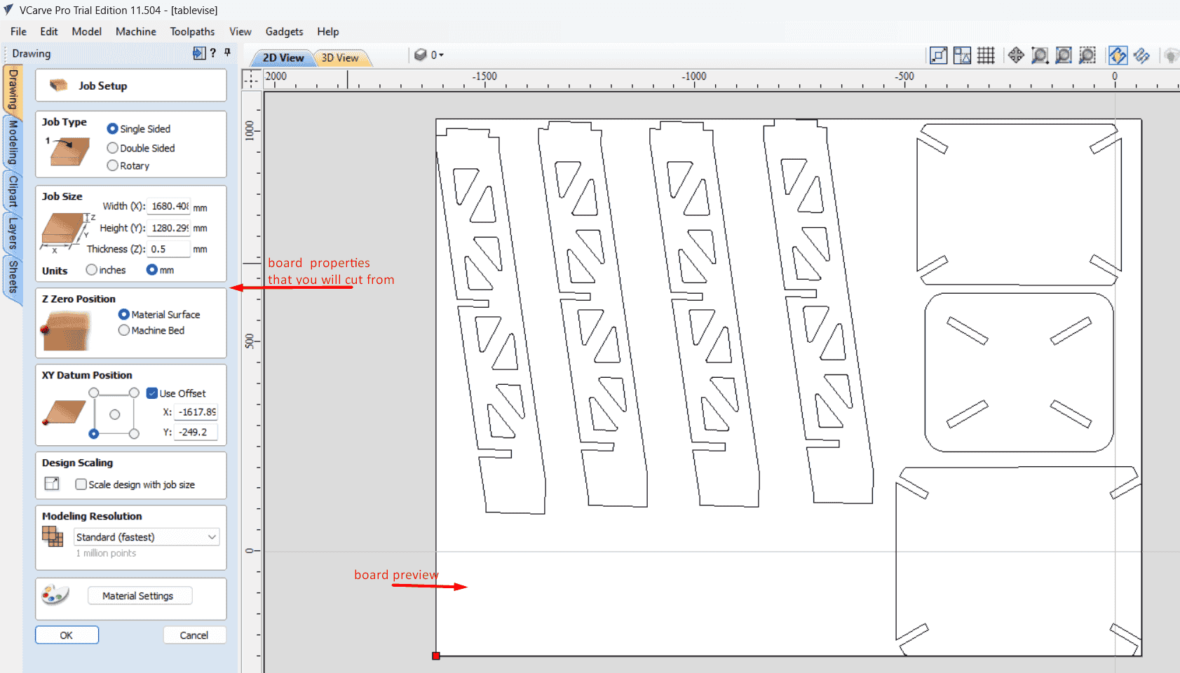
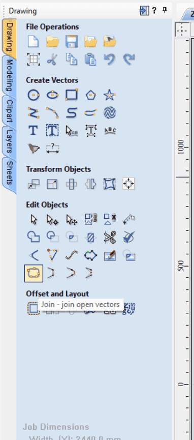
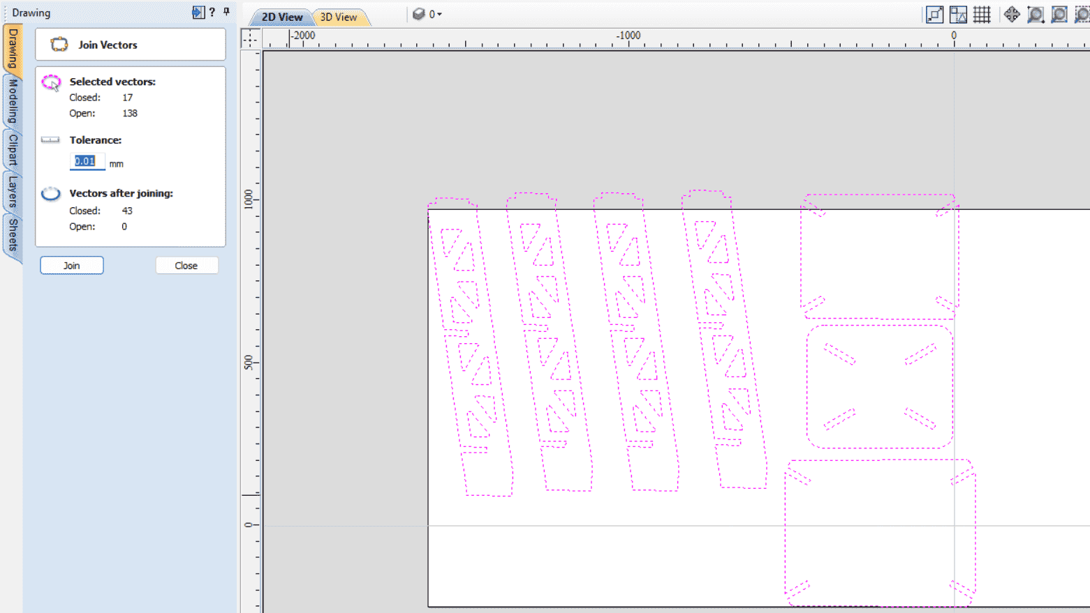
In workspace in the right side you can find tools to help you in modifying your 2d design like drawing different shapes and delete and add line , for me I join the vector part to make the software see it as close loop by using join tool ,that will help in having a single clear tool path.
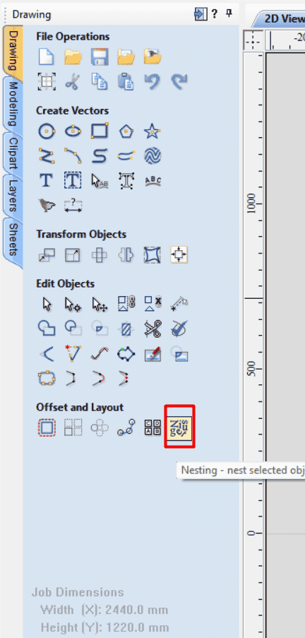
there is a very useful tool called nesting that help you in sorting your 2d shapes in the board in easy way ,that will save space and reduce time used in sorting your shapes
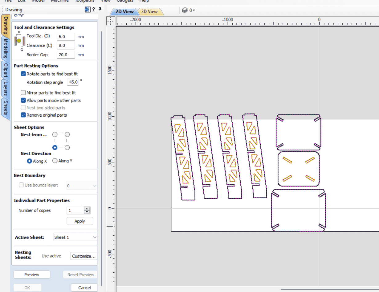
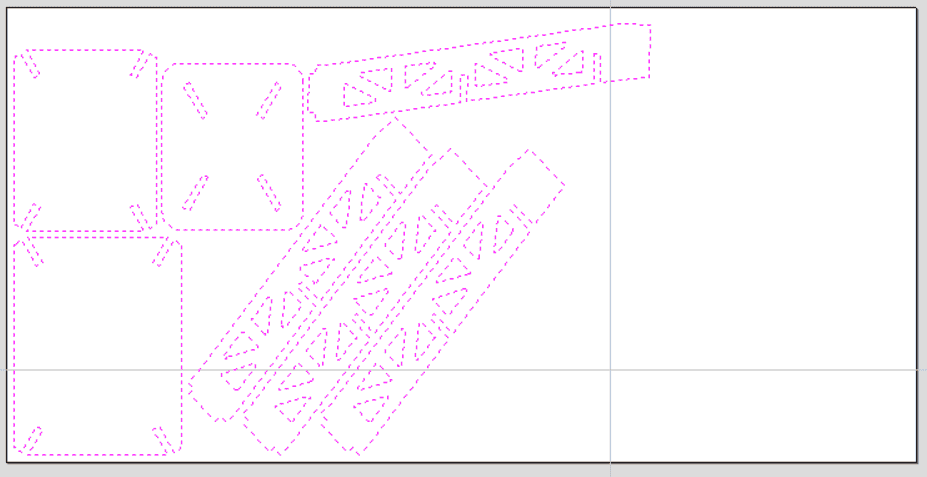
now , we will start with making the tool path programme ,my tool path will be a profile cut path , in the right side of the work space there is a tool for creating a profile tool path that just cut profiles
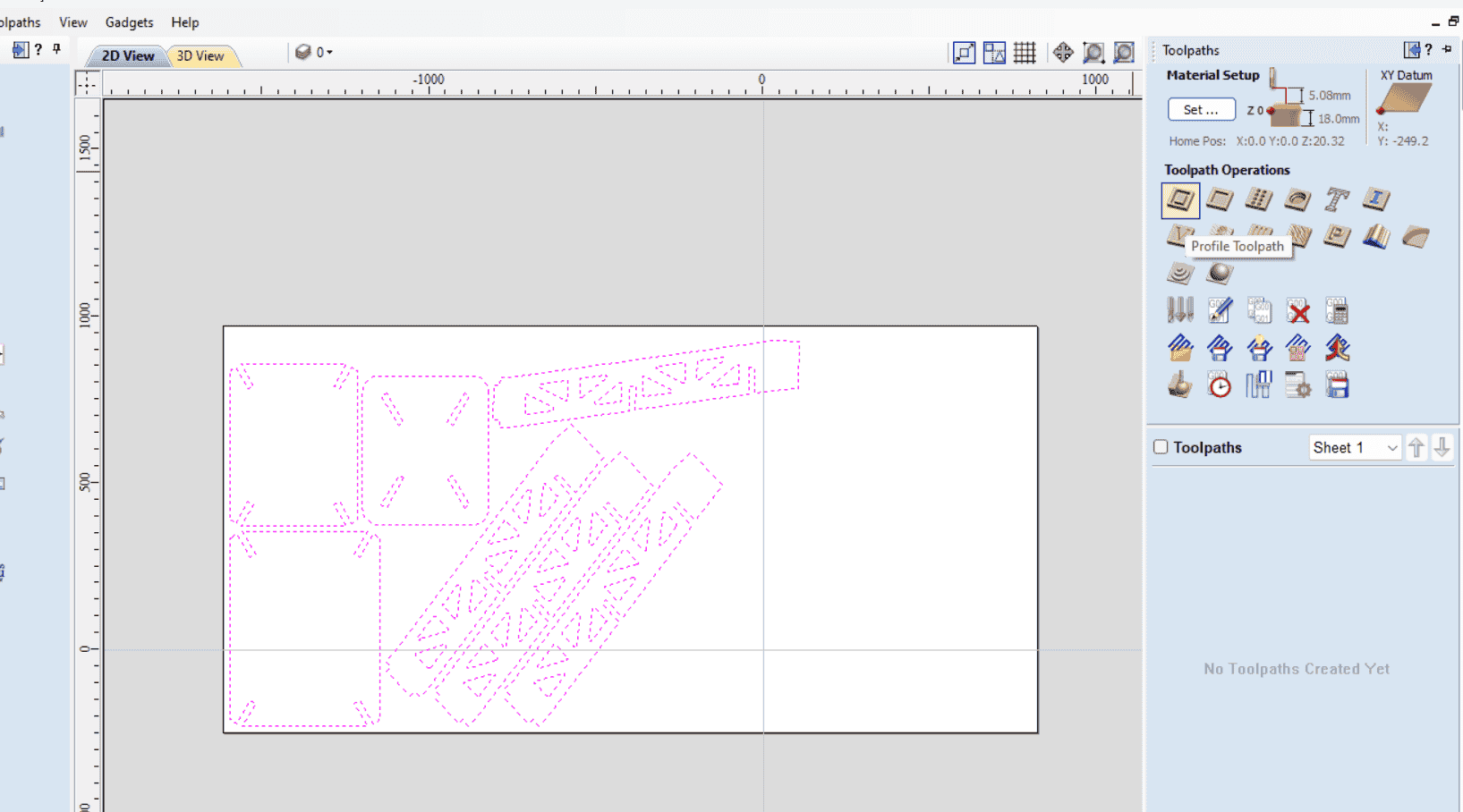
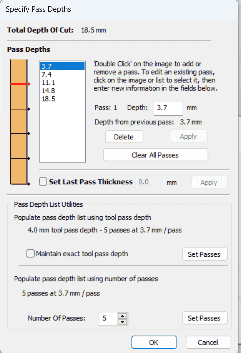
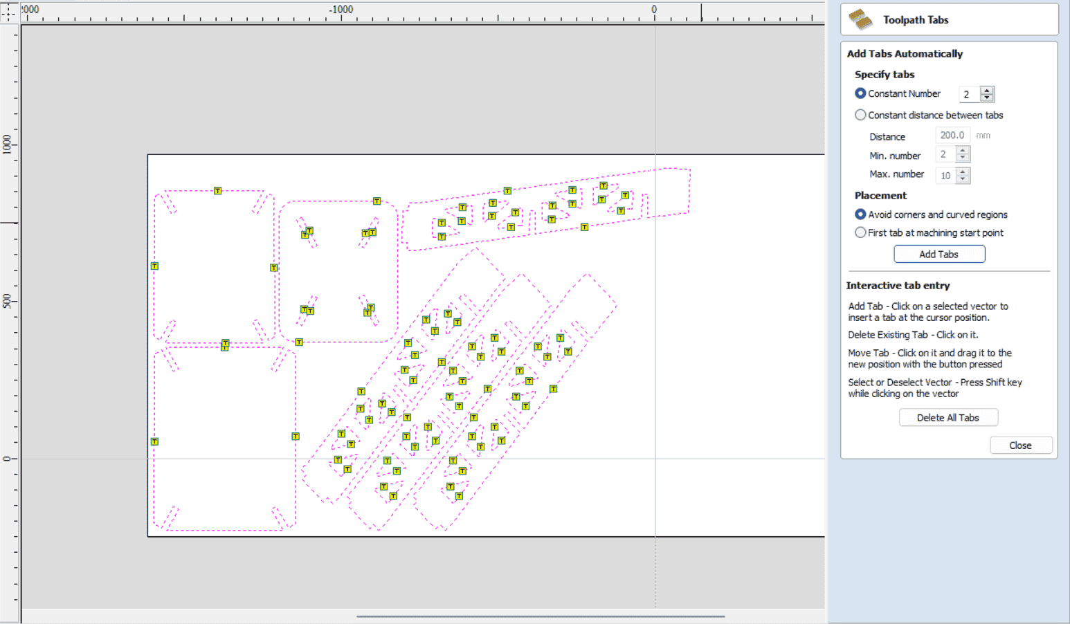
so, now we will add the depth of cut as 18.5 mm,the tools information diameter ,feed rate and plunge rate ,there is a useful calculator for calculate these values FS_Wizared calculator ,or using the above equation , also we can determine the number of passes that the tool will move until it will reach the end depth ,there is also a tabs section that it will be responsible to hold down the piece when the tool cut the profile path
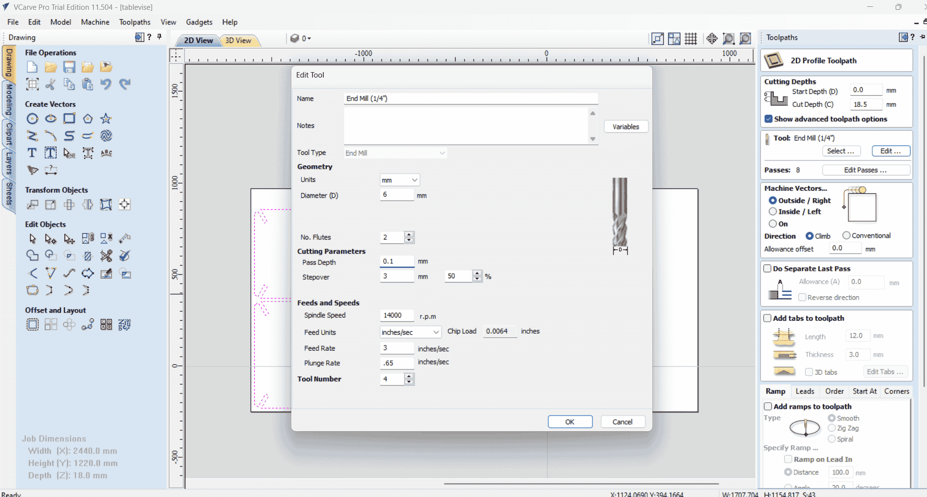
Passes depth section
Adding tabs section
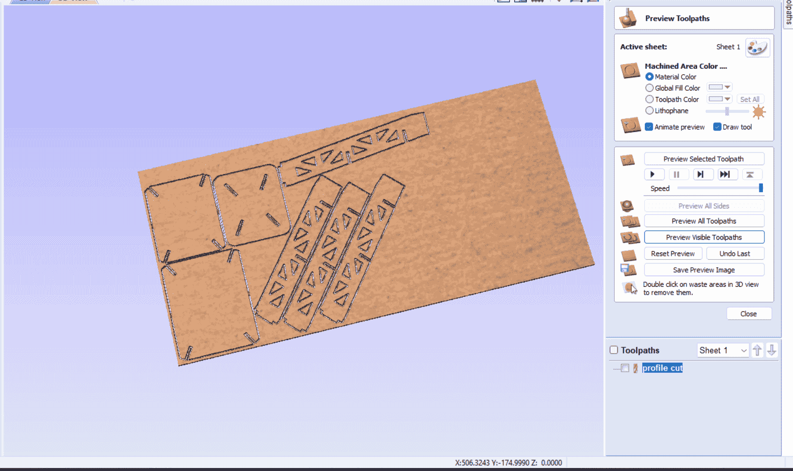
simulation part to check your tool path
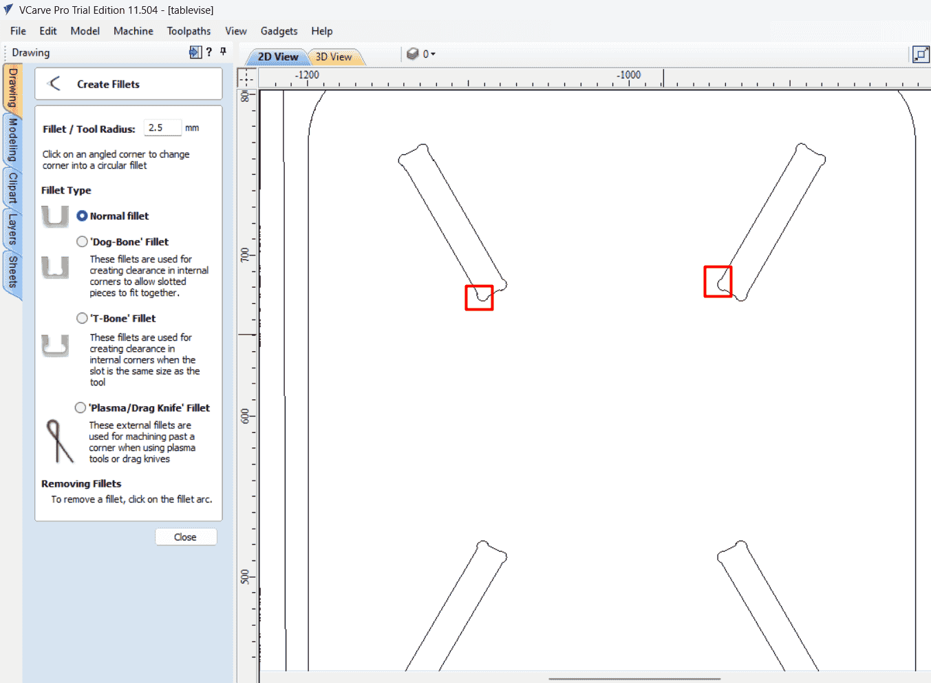
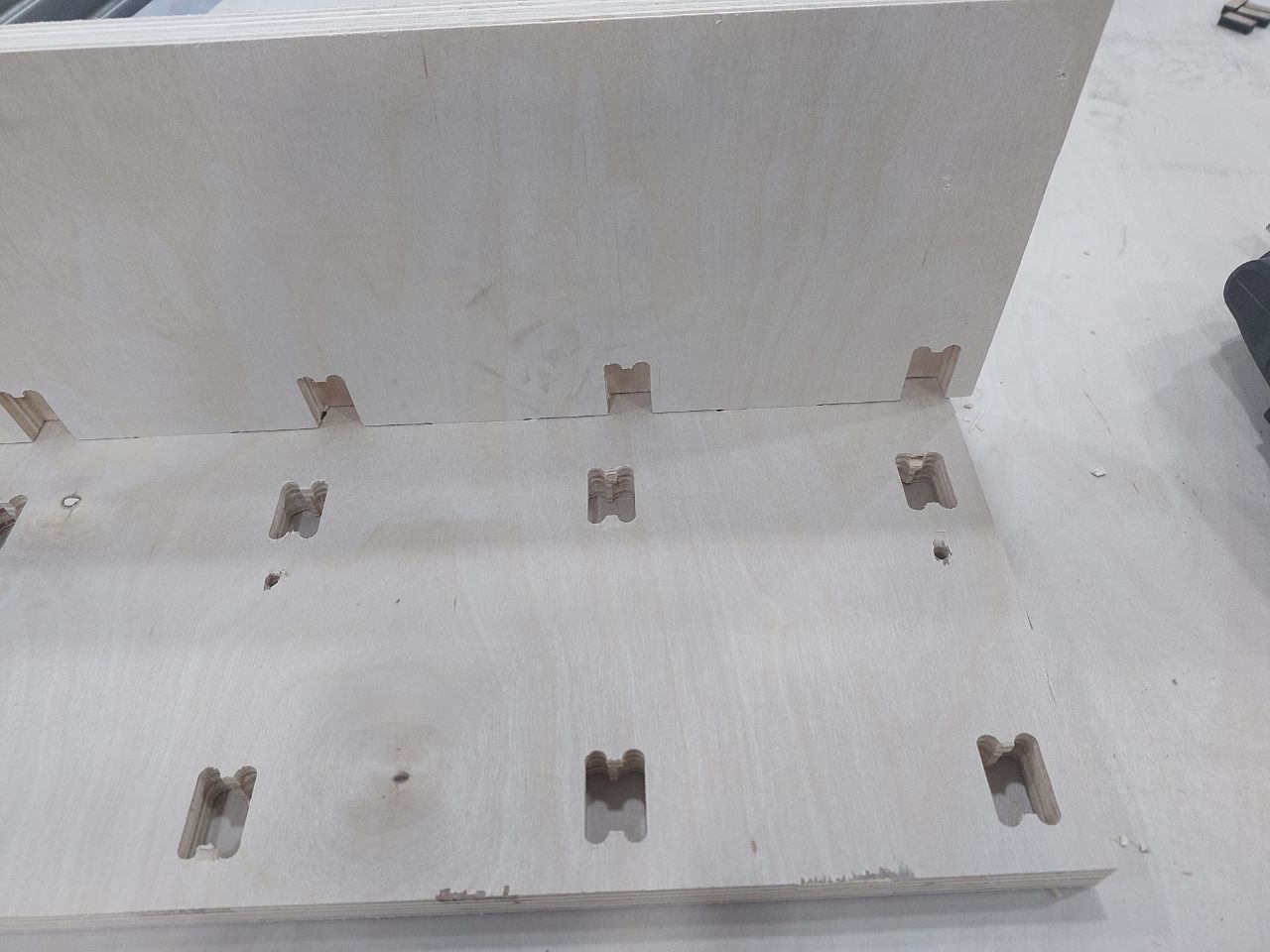
a very important note that I don't mention it early ,that when you make a press fit method you should put filet at sharp edges ,since the tool shape is curved and it cant make your sharp edges and it will make them curved ,so that you should add fillet or dog bone shape , this will help in combining the parts in correct way
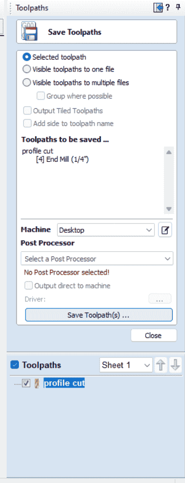
now I will save the toolpath as below
cnc workflow
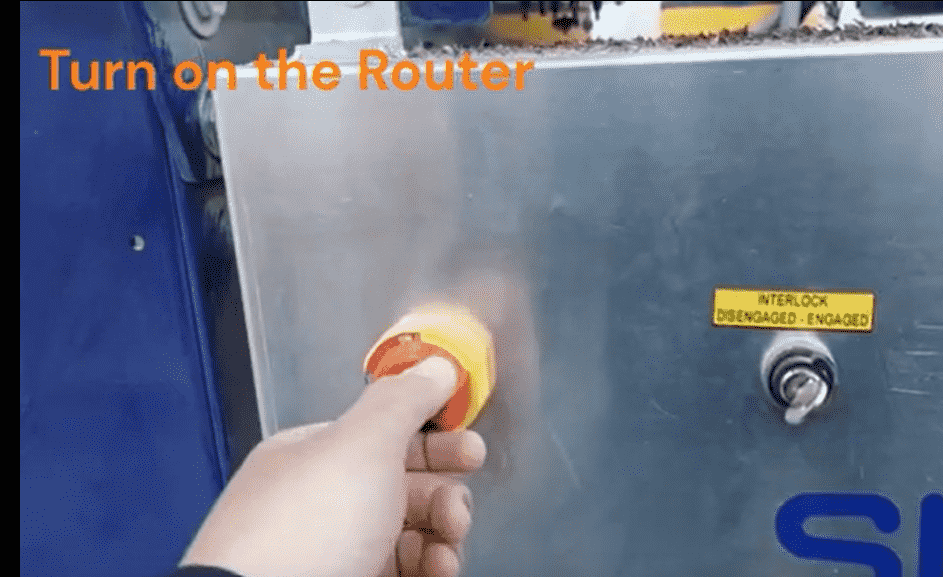
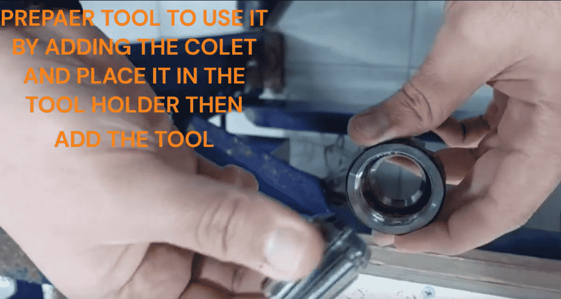
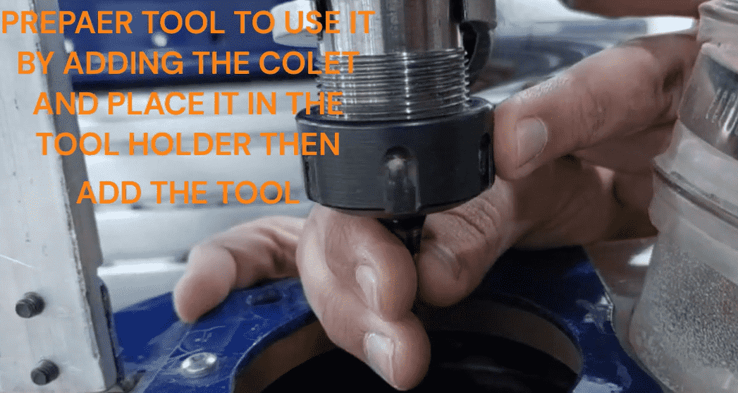
so in the following video you will find the workflow that I flow which start with turn the router machine on ,add the cutting tool to the tool holder find the z zero then add the file for cutting
steps summarize :
- Turn the router on by using the switch.
- Change the tool by adding the proper collet.
- Move the router tool towards the wood piece and find the Z zero.
- Find the X and Y zero from the proper place and set them in the machine .
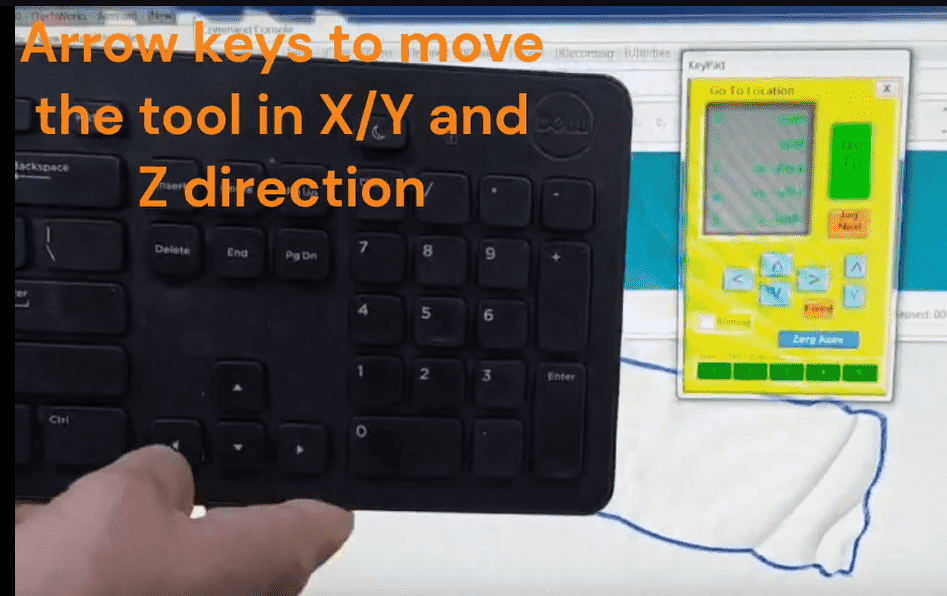



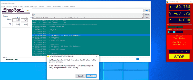
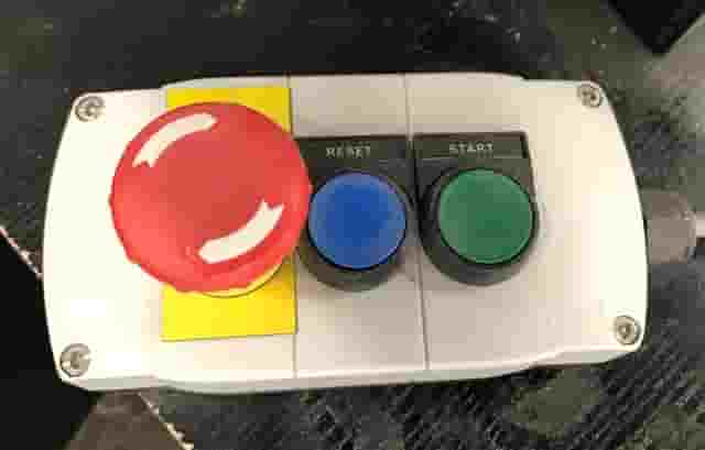
chose the file to cut and start router rotation , and the cutting magic will start
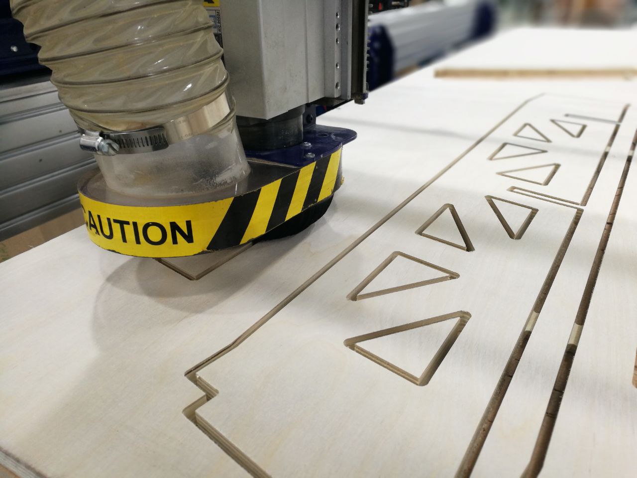
the final design look like this
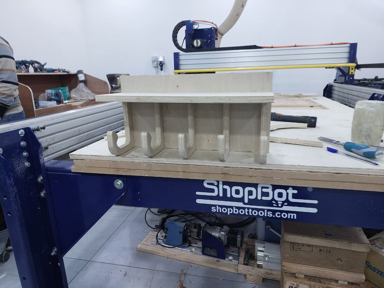
I make another product which is a clothes hanger , I follow the same process
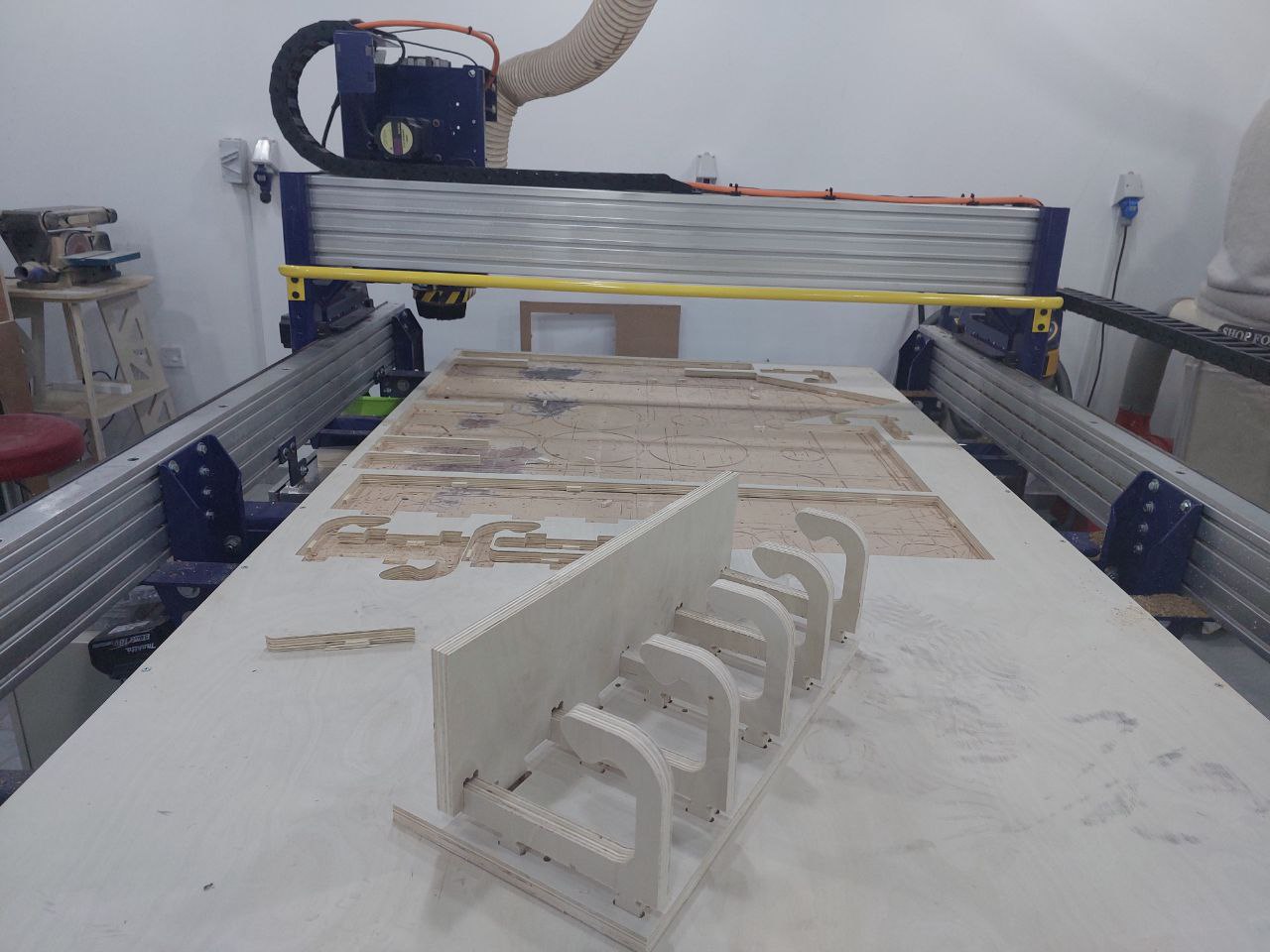
this is how it look like
.svg)

