Week 9: Input Devices
Group Assignments:
We want to test two types of input devices, one gives digital signal(pushbutton), and the other gives analog signal(light sensor), we used the digital multimeter to read the voltage across the resistor for the following circuits:
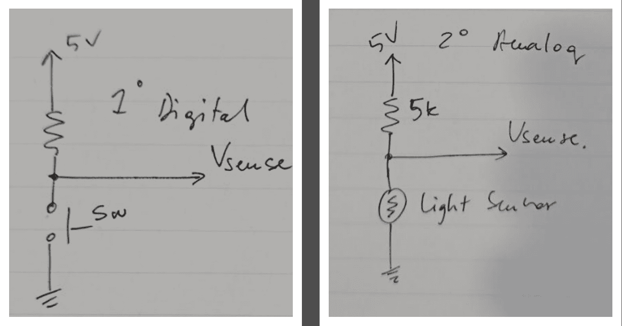
For the pushbutton circuit we supplied the circuit with 5 volt and we used a 5k ohm resistor, when we pushed the button the current flows across the resistor and the voltage reading on the multimeter was exactly the same as the supplied, and it was either 5V or Zero:
The video below shows how it works:
For the LDR(Light Dependent Resistor) is sensitive to the light, when the amount of the light that falls on the LDR increases , the resistor will decrease, the voltage across the LDR will decrease and we noticed that the value of the voltage was ranging and does not have a fixed value like pushbutton.
The video below shows how it works:
Digital signals are characterized by a two-state system represented by the values 0 and 1. When a digital signal is in the state of 0, it signifies a low voltage level, typically 0V. Conversely, when the signal is in the state of 1, it represents a high voltage level, which may vary depending on the specific logic voltage of the system.
On the other hand, analog values encompass a broader range and exhibit continuous changes over time. For instance, when the amount of light directed to a Light Dependent Resistor (LDR) varies, the voltage associated with the analog signal connected to the LDR also fluctuates correspondingly.
To summarize, digital signals operate in a binary fashion with distinct 0 and 1 states, whereas analog signals encompass a continuous range of values that change in response to varying conditions, such as light levels affecting an LDR.
Individual Assignments:
In this week I need to add an input device to a microcontroller , so I use SMD21 MCU and a light sensor (Photodarlington as input device) and a led
what I am plan to do is to control the built in led by light sensor reading
An input device is a component or peripheral that allows users to provide data, commands, or signals to a microcontroller or computer system. Input devices capture information from the user or the environment and convert it into a digital or analog format that can be processed by the microcontroller or computer.
Input devices come in various forms, and they enable users to interact with systems, provide instructions, or input data. They can be categorized into different types, such as sensors, switches, buttons, or interfaces, depending on their specific functionality.
Device Description
so I used Photo Darlington sensor that will be my input device for this week to control a led
Photodarlington Sensor
Overview
A photodarlington sensor, also known as a photodarlington transistor or photodarlington pair, is a type of optoelectronic device that consists of a phototransistor connected in a darlington pair configuration. It is widely used for detecting and measuring light intensity in various applications.
Key Features of Photodarlington
- Working Principle: A photodarlington sensor utilizes the internal workings of a phototransistor, which is a light-sensitive semiconductor device.
- Sensitivity: Photodarlington sensors are highly sensitive to light and can detect even small variations in light intensity.
- Response Time: These sensors typically have a fast response time, allowing them to quickly detect changes in light intensity.
- Low Noise: Photodarlington sensors exhibit low noise characteristics, ensuring accurate and reliable light sensing.
- Wide Dynamic Range: These sensors can operate over a wide dynamic range, making them suitable for various lighting conditions and environments.
Applications
- Light intensity monitoring and control systems
- Optical communication systems
- Optical switches and encoders
- Ambient light sensing in displays and lighting systems
- Optical detection and counting in industrial automation
- Proximity sensing and object detection
for more detail you can check the data sheet here
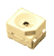
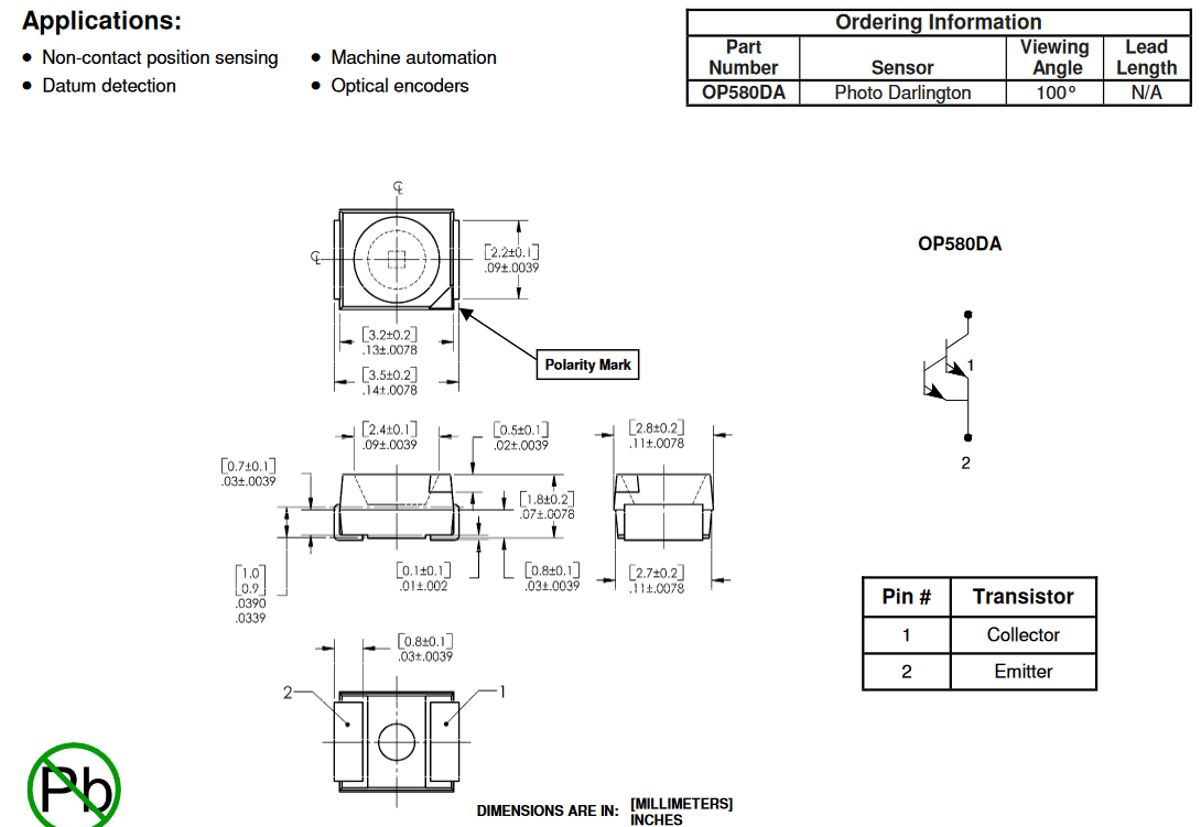
for led I will used the built in led on smd21 and a 10k ohm resistor to connect it with photo sensor
XIAO SAMD21
Overview
The XIAO SAMD21 is a compact microcontroller board based on the SAMD21G18A microcontroller chip. It is designed for small projects requiring a powerful yet compact microcontroller.
Key Features and Specifications
- Microcontroller: SAMD21G18A, ARM Cortex-M0+ 32-bit processor, 48 MHz clock speed
- Memory: 256 KB Flash, 32 KB SRAM
- I/O Pins: 14 digital I/O pins (11 with PWM support), 10 analog input pins
- Interfaces: USB, UART, I2C, SPI
- Power Supply: 3.3V to 5V
- Size and Form Factor: Compact size, 20mm x 17.5mm
- Programming: Arduino IDE compatible
Applications
The XIAO SAMD21 is suitable for a wide range of applications, including:
- Wearables
- IoT (Internet of Things) devices
- Robotics
- Sensor interfacing
- Embedded systems
- Prototyping
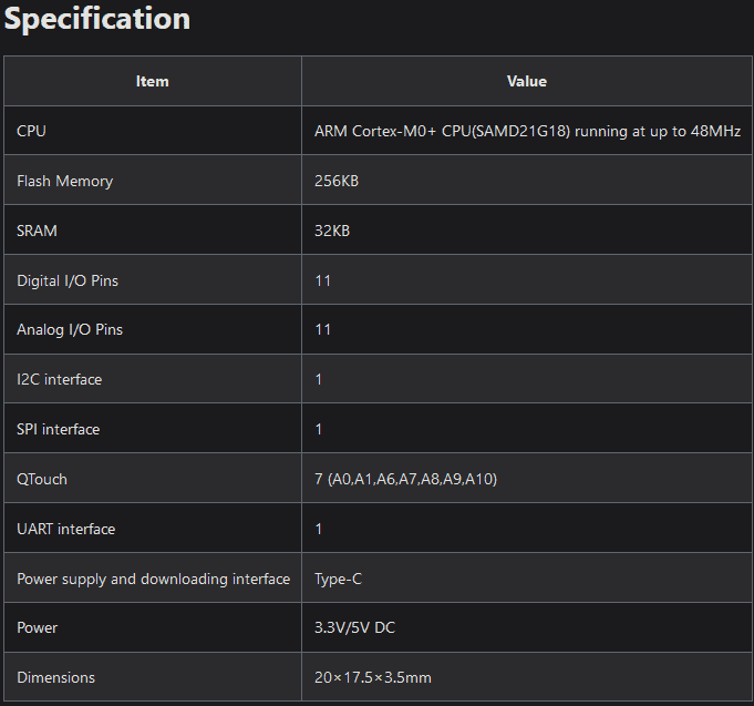
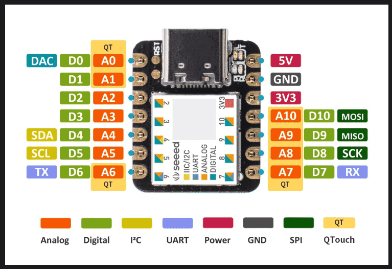
you can read more about its specification from its data sheet
Board Design & Fabrication
I design my circuit using Eagle software
Eagle schematic and Board
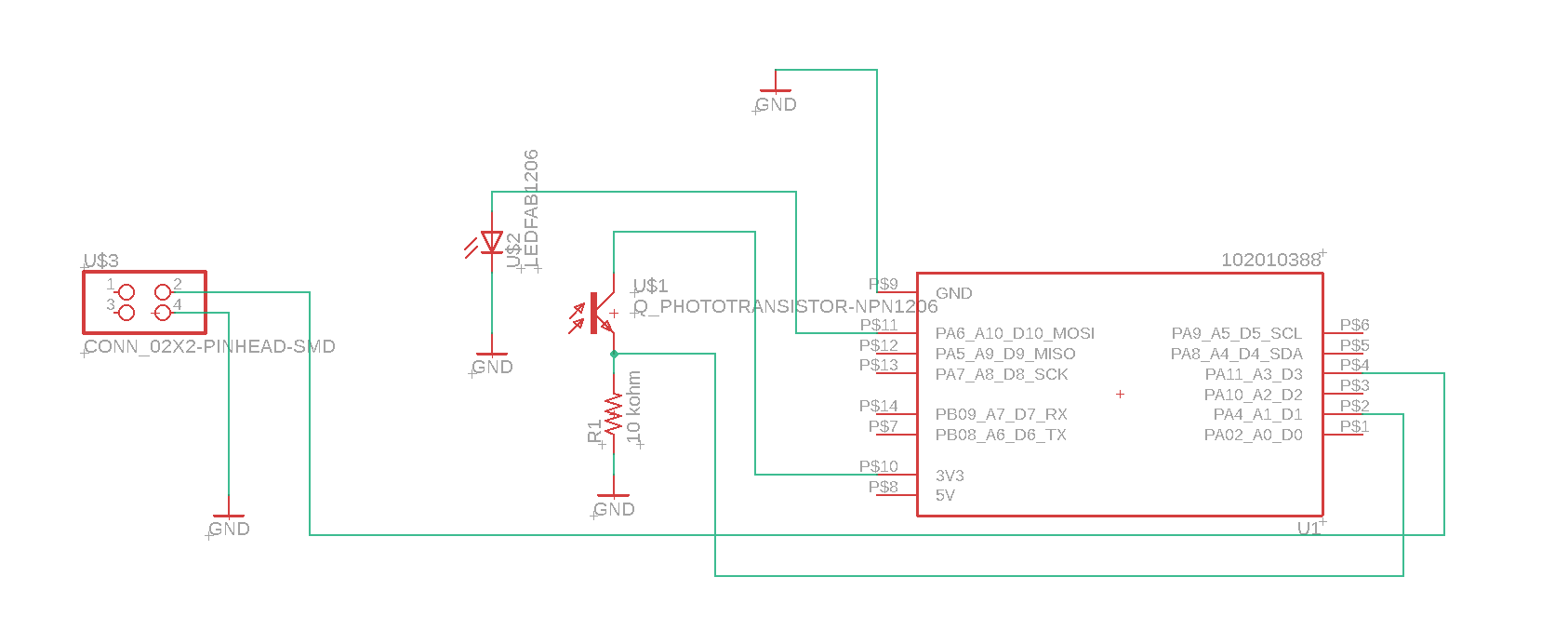
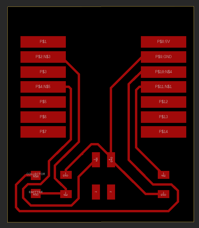
you can see that The photodarlington sensor requires the following connections:
- Connect the sensor's collector side to the 3V pin of the microcontroller.
- Connect a resistor between the sensor's output pin and ground. This resistor helps stabilize the output value and provide better measurement accuracy ,and I learned this in hard way when I miss that and try to read the sensor value it give me a very unstable readings.
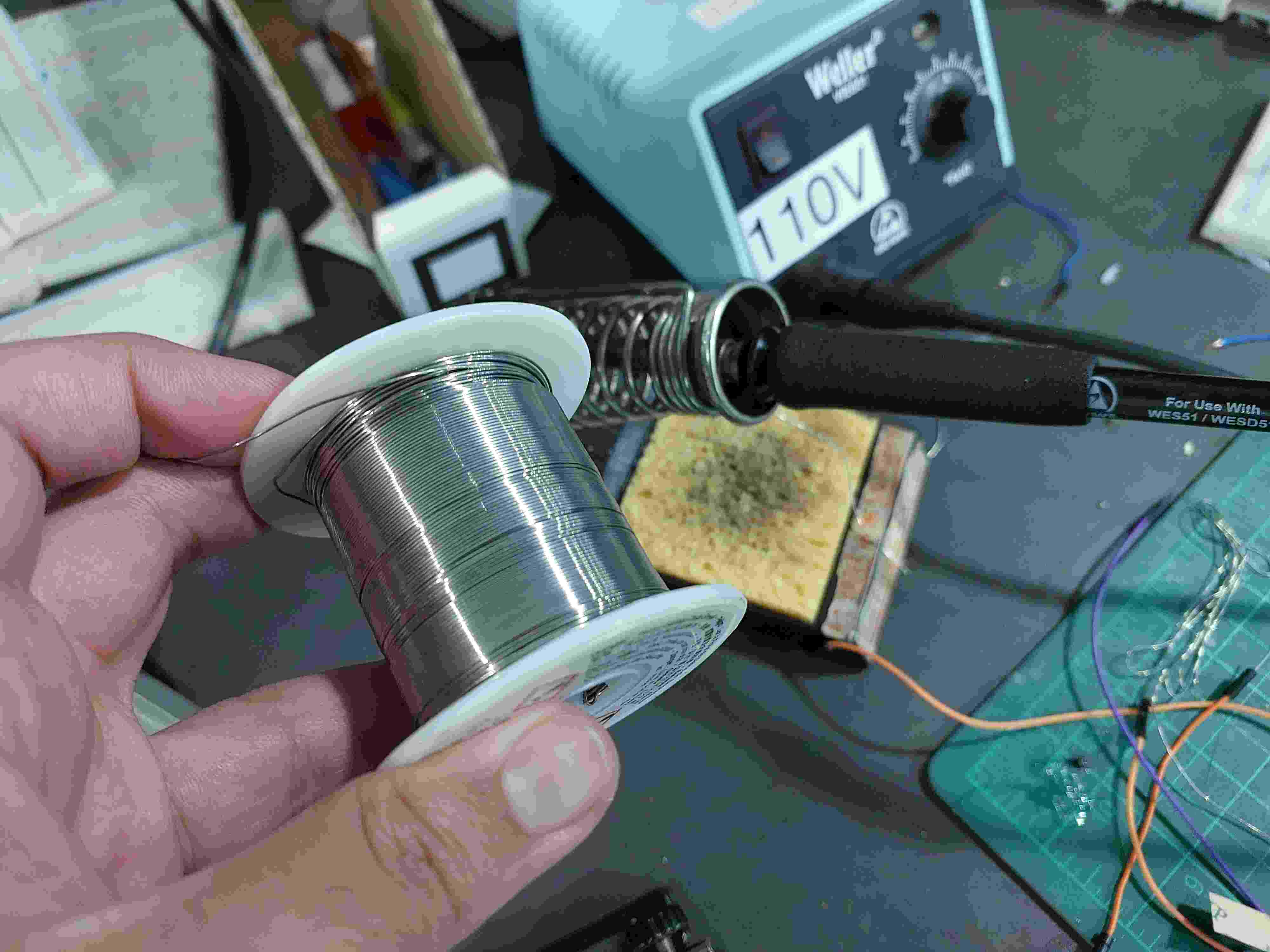
milling the pcb using Roland srm-20 machine ,fix the copper plate at the bed of machine using double face tape then soldering the component on the board , unfortunately my xio esp32 c3 break down so i use the smd21 mcu also after connecting smd led I figure out that it isn't working it burn out, so I think that It will like opportunity to learn how to use the builtin led in the smd21 mcu

Soldering
Programming
            const int lightSensorPin = A1;  // Analog pin connected to the light sensor
            const int ledPin = D10;          // Digital pin connected to the LED

            int threshold = 300;  //set the light threshold

            void setup() {
              pinMode(ledPin, OUTPUT);        // Configure LED pin as output
              pinMode(LED_BUILTIN, OUTPUT);
              Serial.begin(9600);             // Initialize serial communication (optional)
            }

            void loop() {
              int sensorValue = analogRead(lightSensorPin);  // Read the sensor value
              // Serial.println(sensorValue);

              if (sensorValue > threshold) {
                digitalWrite(ledPin, HIGH);  // Turn on the LED
                digitalWrite(LED_BUILTIN, HIGH);   // turn the LED off (HIGH is the voltage level)
              } else {
                digitalWrite(ledPin, LOW);   // Turn off the LED
                digitalWrite(LED_BUILTIN, LOW);    // turn the LED on by making the voltage LOW
              }

              Serial.print("Sensor Value: ");  // Print sensor value (optional)
              Serial.println(sensorValue);
                delay(100);  // Delay for stability (optional)


              }
so here in the code I set light sensor threshold if light sensor value below it the built in led on mcu will light off else the light will just turn on
.svg)

