.svg)


Week 4: Embedded Programming
group assignment (compare performance of different microcontroller ) by finding how many iteration can the controller make in 10 second
Arduino nano
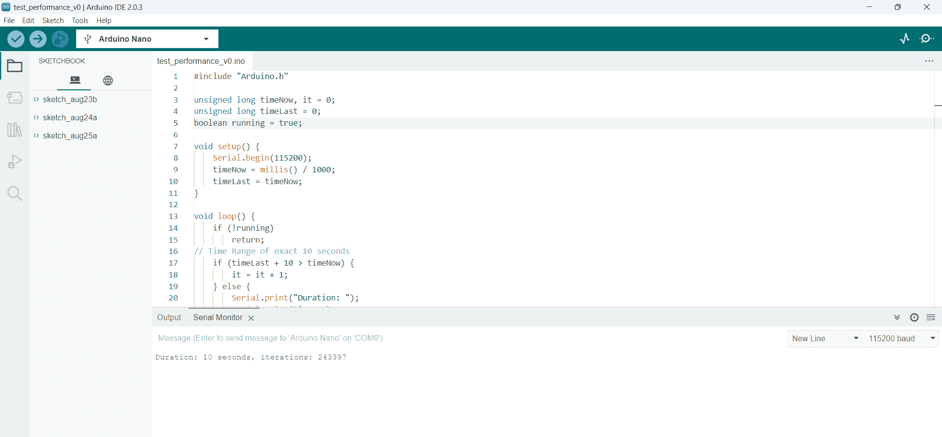

Duration:10s
Iteration:24 33 97
Arduino uno
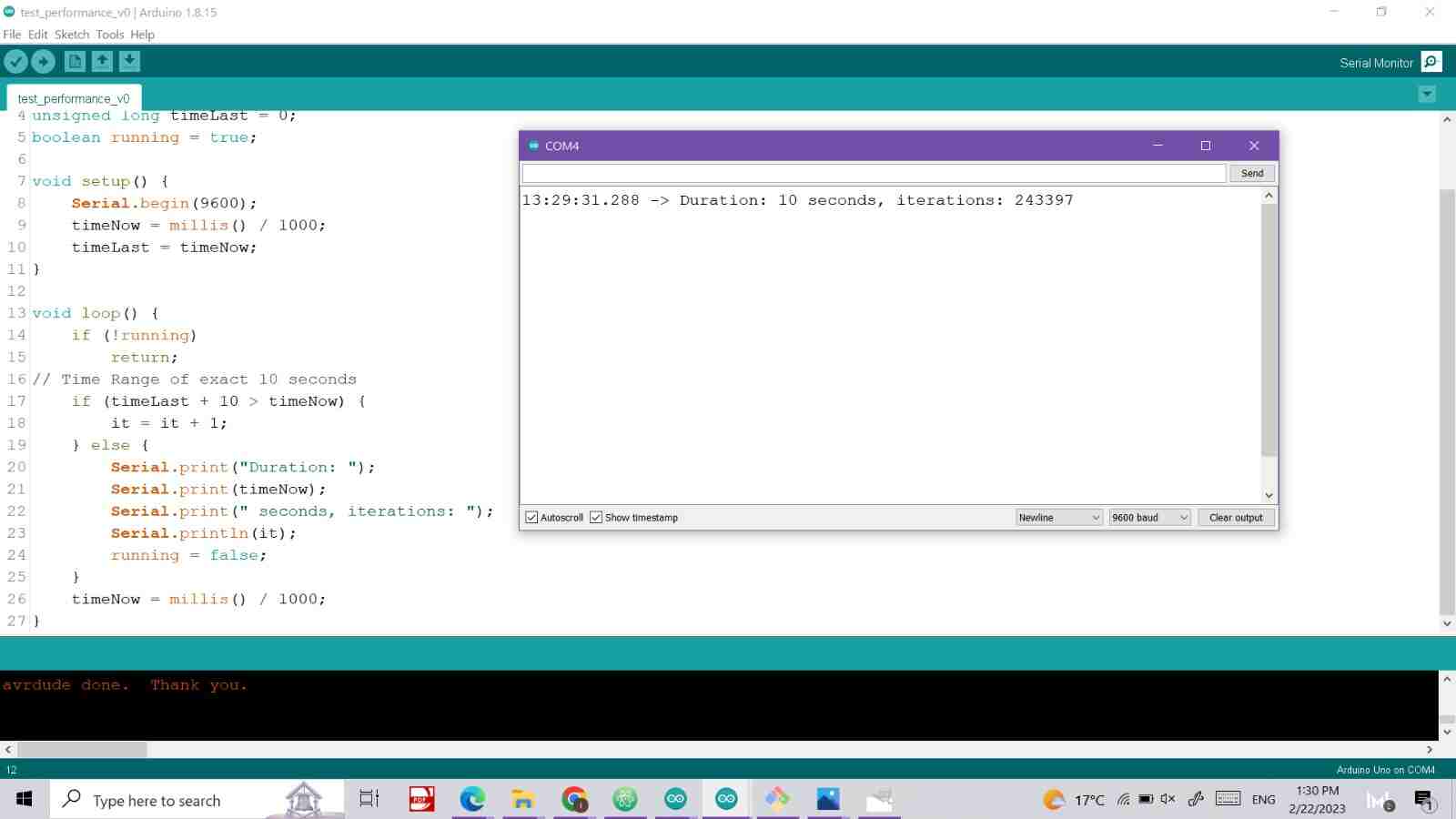
Duration:10
Iteration:24 33 97
Esp-wroom-32
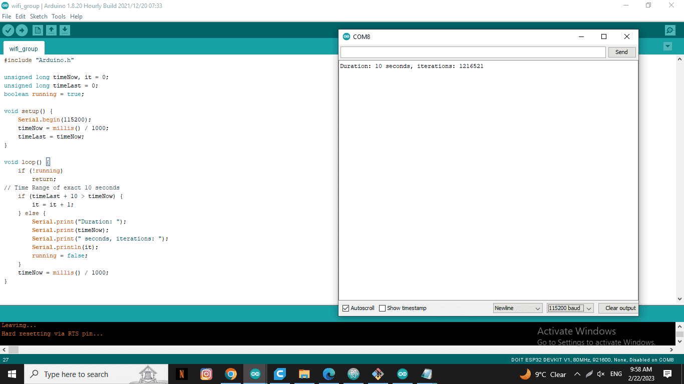
Duration:10
Iteration:12 16 52 1
XIO-RP-2040
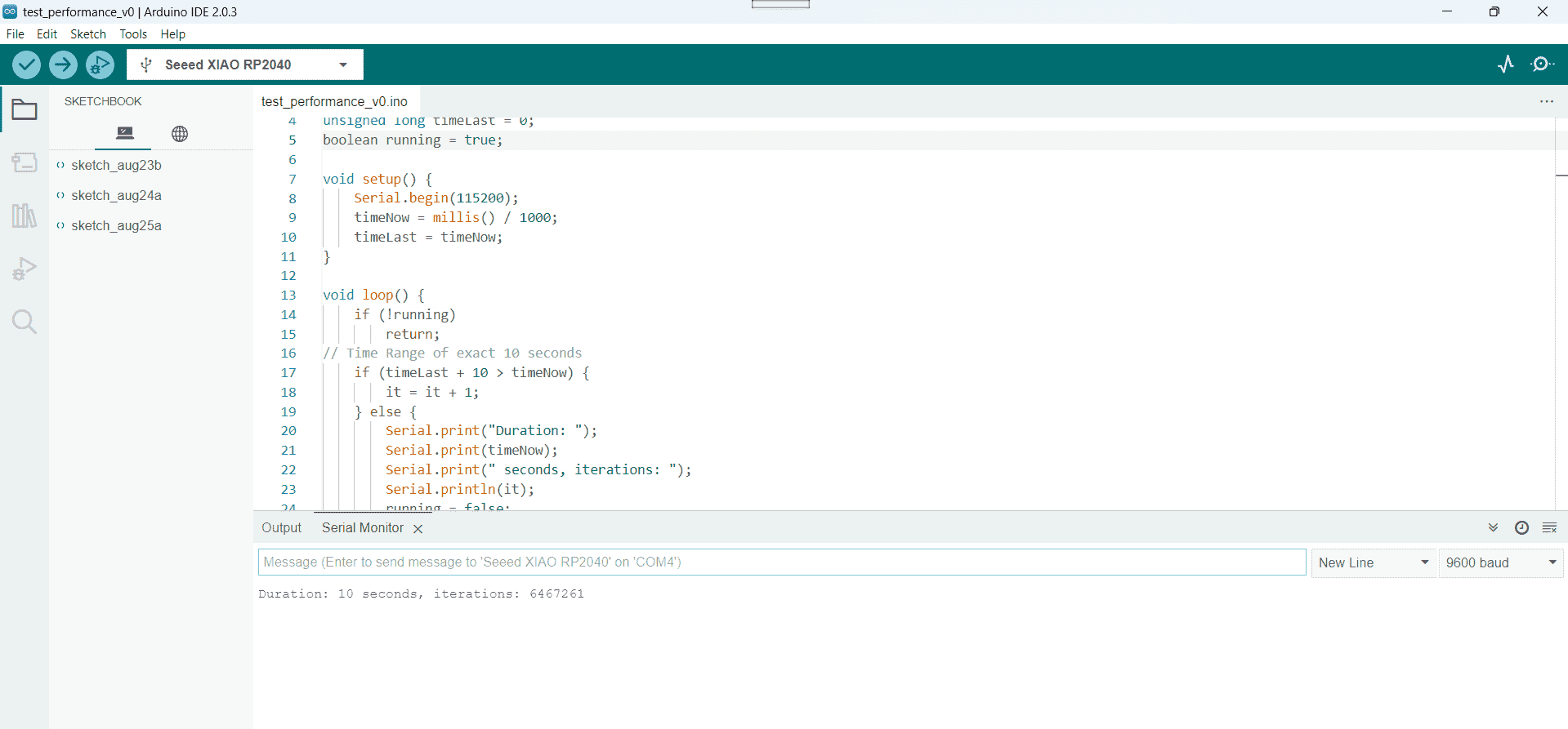
Duration:10s
Iteration:64 67 26 1
Xiao ESP3-C3
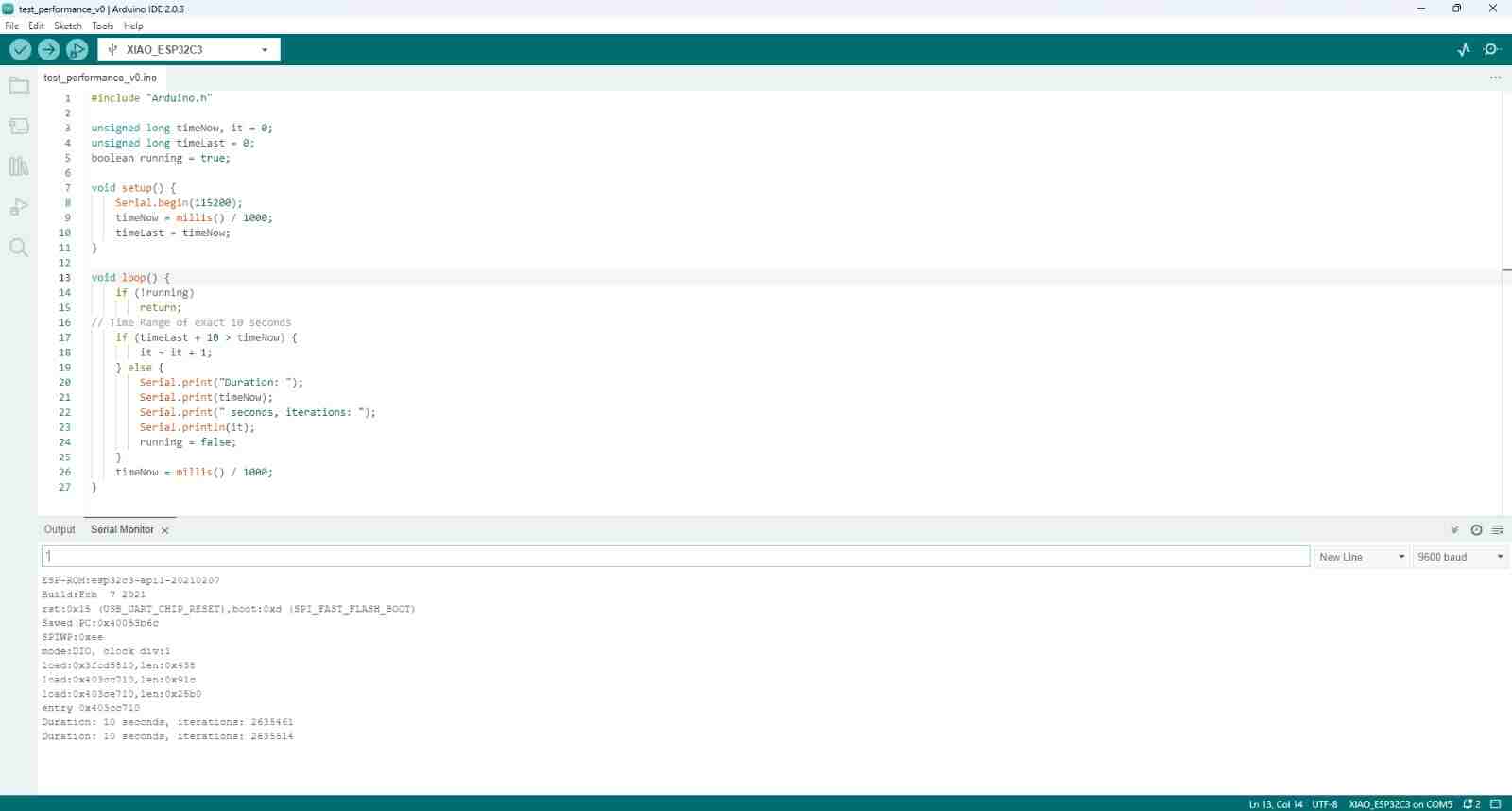
Duration:10
Iteration:26 35 51 4
Conclusion:
By this comparison I just learn that there is a difference between the performance of the microcontroller and that they are work with different speed ,So if I have an application that need fast computing action I will try to search for a microcontroller with high speed as in our comparison we find that Seed-RP-2040 is the fastest controller and arduino controller (nano , uno ) almost have the same speed
What is the microcontroller ?
it is a small computer (or in more detail definition microcontroller is an integrated circuit that is programmed to do a specific task) you can find them in almost all electrical appliance that are around you
Microcontrollers are typically programmed in higher-level languages such as C++,python or Java. One of the essential tools needed to program a microcontroller is an Integrated development environment (IDE) . This software is usually developed by the creators of the microcontroller, and contains useful tools to help you program your microcontroller. Common tools found in IDE's include, code editors, compilers, and debuggers.
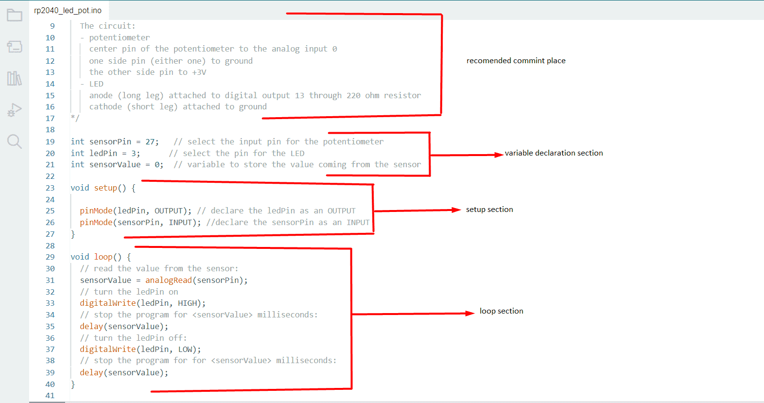
So, for me I use the arduino IDE to programme my controller , from coding aspect code contain three main section
,Variable declaration section,setup section and loop section .firstly , Variable section which is
contain all the variable that you will use it in your programme ,These variables are global, and
can be called in any sections that follow. It is also common to create variables to
describe each pins function, and set them equal to the pin number on the board to
make coding more intuitive
Secondly, Void Setup() section , Digital pins on microcontrollers
are commonly used as inputs or outputs. In this section, the user defines which pins
are inputs or outputs, as well as any other parameters that must be initialized.
Thirdly, Void Loop() section,This section is where the function of your
microcontroller is written. Any actions that require reading or writing values from
pins, or computing the values of different variables is done here
Lastly,usually we add at the top of our code a description of the code and any other important information related to that as a comment
Once our code is written, it must be uploaded to the microcontrollers and here is come the Job of the compiler ,
A compiler is a software tool that takes higher level code and optimizes it for a language suitable for micorcontroller
to push the code to the controller I use a type c cable to transfer the code ,but before pushing it to the controller you should identify the microcontroller in Arduino IDE
as below then click on upload button
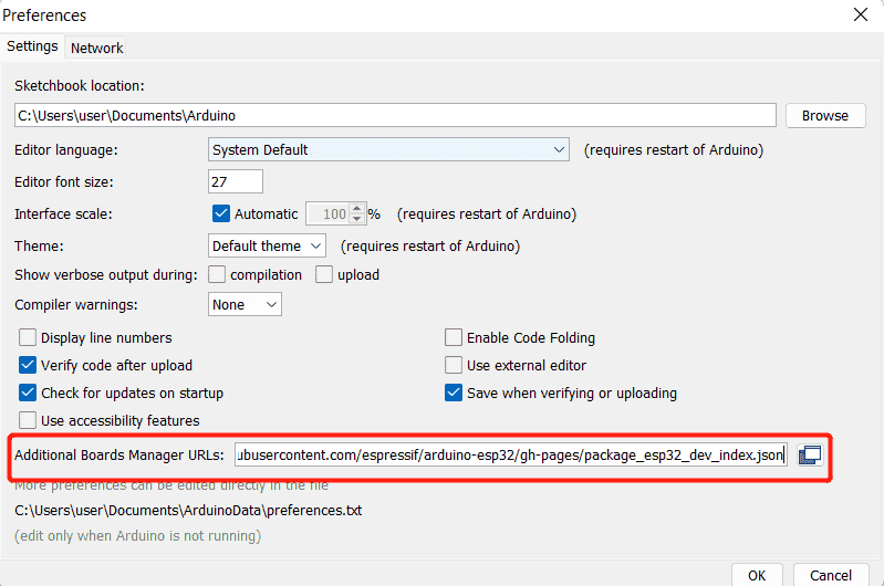
Navigate to File > Preferences , and fill "Additional Boards Manager URLs" with the url below:
https://raw.githubusercontent.com/espressif/arduino-esp32/gh-pages/package_esp32_dev_index.json
note :"Additional Boards Manager URLs" is a very important features in Arduino Ide ,
that allows you to add custom URLs to the Boards Manager. The Boards Manager is a tool in the Arduino IDE that makes it easy to install and manage different board definitions for various microcontroller platforms.
By adding additional Board Manager URLs, you can access third-party board definitions that are not included in the default installation of the Arduino IDE. This makes it possible to work with a wide range of microcontrollers
and development boards beyond the ones that are officially supported by Arduino.
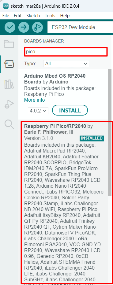
now You should go to the board manager and install new board definitions for our Microcontroller (Raspberry pi pico/RP2040)
steps to follow:
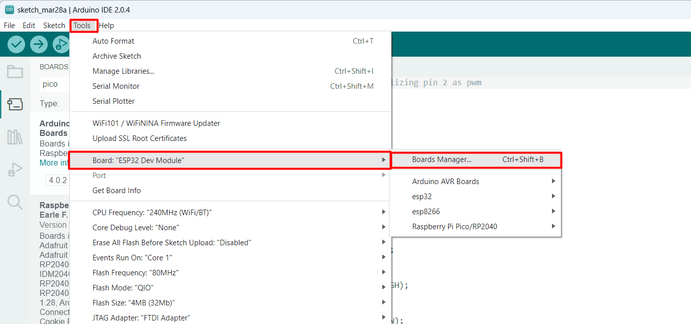
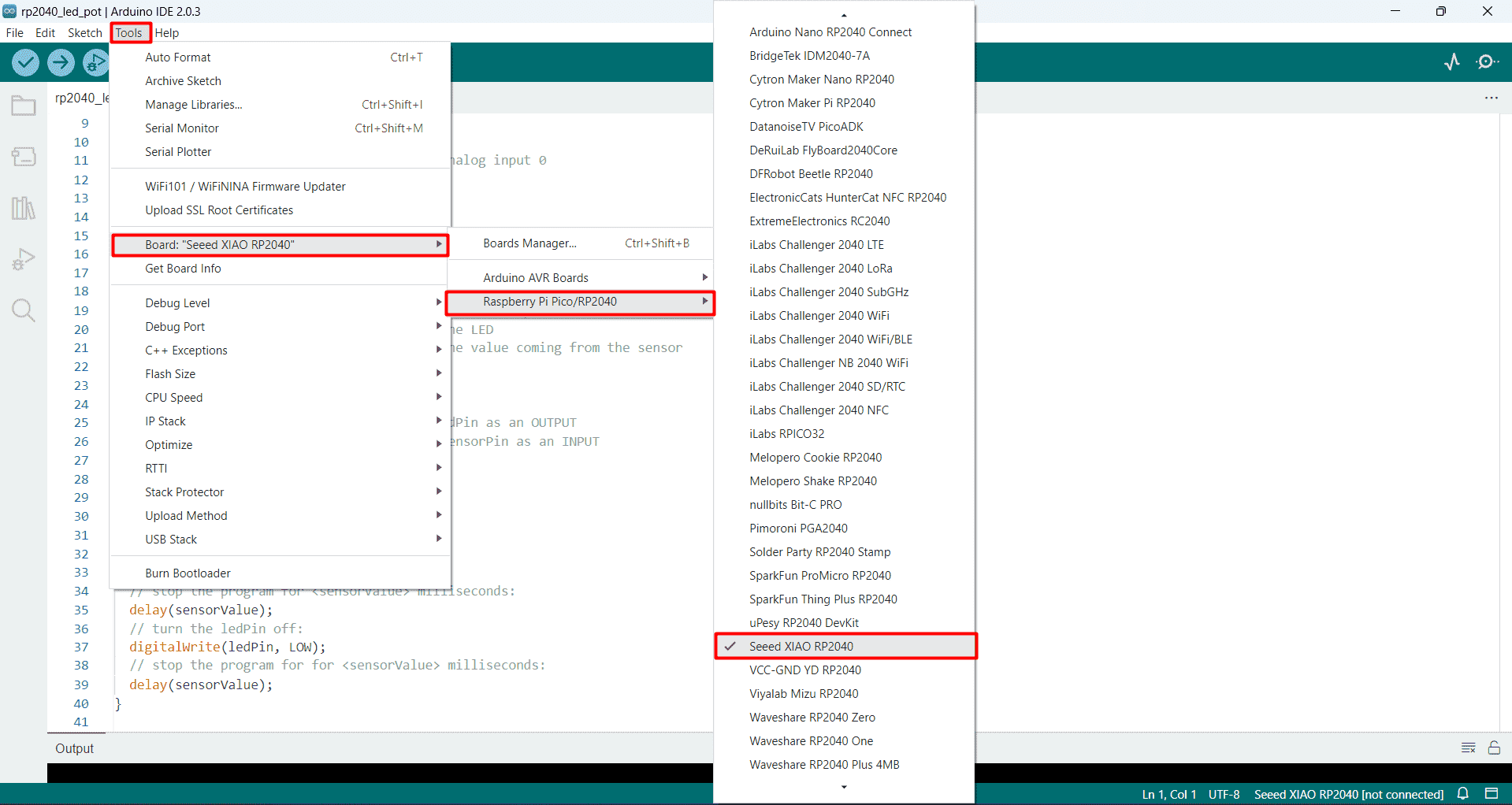
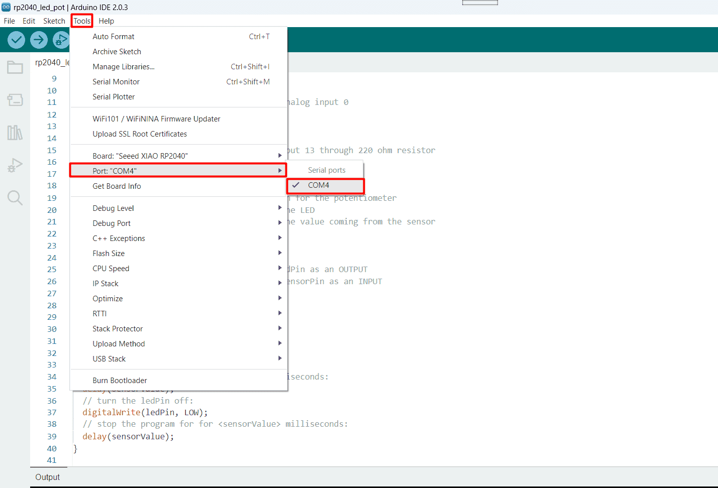
then you chose your board name and add the port (the usb channel) you work with like this
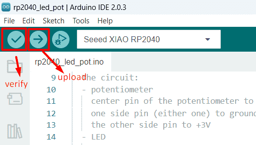
after that you just verify the code to check if their is any error in your code ,then you upload the code all that happen at the top bar in the Arduino IDE
For me I use a XIO-RP-2040 microcontroller to control a led using potentiometer and I simulate it using Tinkercad website its so useful but on simulation I used arduino uno
Mcu feature:
- Operating Voltage: 3.3V
- Input Voltage: 7-12V
- Digital I/O Pins (DIO): 11
- Analog Input Pins (ADC): 4 but only 3 are usable
- Analog Outputs Pins (DAC): 0
- Flash Memory: 2MB
- SRAM: 264KB
- Clock Speed: 133MHz
- Perfect for Production: Breadboard-friendly & SMD design, no components on the back
all those information you can find it out from wiki.seeedstudio or from its data sheet
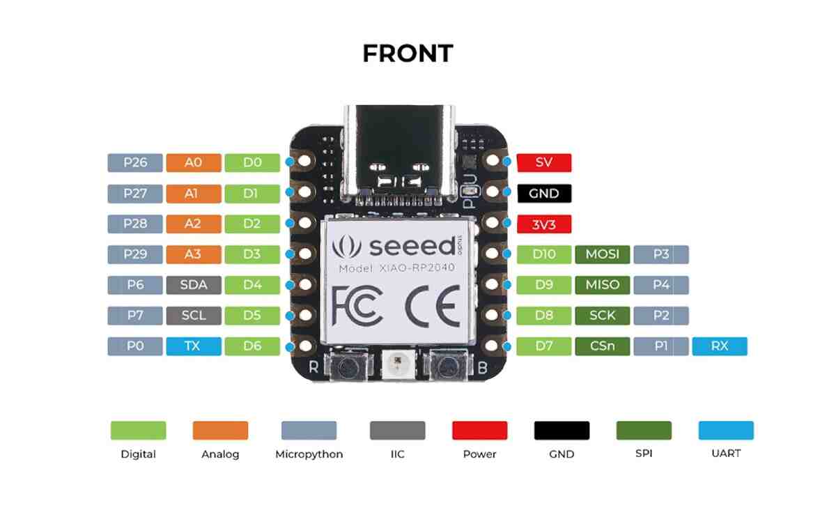
pin layout
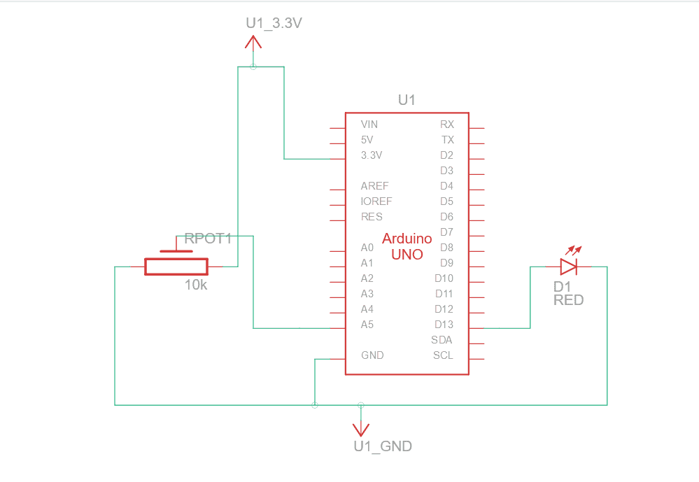
circuit simulation using tinkercad (this website give you all the component that you need for your circuit)
and this is the pin microcontroller description image " D " refer for dialog input/output pins that mean (0 or 1/ low or high /on or off) and " A " refer to analog pins (that can read and write range of value)
So, I write the code and upload it to my controller ;the code give instruction for the controller as below
- turn the led off when the resistance of the potentiometer less than 5
- turn the led on when the resistance of the potentiometer larger than 999
- other than above two conditions make the led blinking on and off with delay value between led action (on/off) equal to the potentiometer resistance value
so this code our instructor help us to establish it,I change the code in the void setup,by adding my conditions using (if statement and while loop),below you will find comment on each line explain the code
                int sensorPin = 27;   // select the input pin for the potentiometer
                int ledPin = 29;      // select the pin for the LED
                int sensorValue = 0;  // variable to store the value coming from the sensor
                int sensorValue2 = 0;  // variable to store the value coming from the sensor

                void setup() {
                  Serial.begin(9600);
                  pinMode(ledPin, OUTPUT); // declare the ledPin as an OUTPUT
                  pinMode(sensorPin, INPUT); //declare the sensorPin as an INPUT
                }
                void loop() {
                  // read the value from the sensor:
                  sensorValue = analogRead(sensorPin);
                  // turn the ledPin on
                  digitalWrite(ledPin, HIGH);
                  // stop the program for  milliseconds:
                  delay(sensorValue);
                  // turn the ledPin off:
                  digitalWrite(ledPin, LOW);
                  // stop the program for for  milliseconds:
                  delay(sensorValue);
                  // print the value of sensorValue in serial monitor
                  Serial.println(sensorValue);

                  // if statement to check the value of sensorValue
                  if (sensorValue<10){

                    do{
                    // turn the ledPin off:
                    digitalWrite(ledPin, LOW);
                    // read the value of sensorValue to check again
                    sensorValue2 = analogRead(sensorPin);
                    }
                    //check the condition state
                    while(sensorValue2<10);

                  } else if (sensorValue>670){
                    do{
                    // turn the ledPin on:
                    digitalWrite(ledPin, HIGH);
                    // read the value of sensorValue to check again
                    sensorValue2 = analogRead(sensorPin);

                    }
                    //check the condition state
                    while(sensorValue2>670);
                  };
                }
my instructor recommend me another way to write the code ,as below
                int sensorPin = 27;   // select the input pin for the potentiometer
                int ledPin = 29;      // select the pin for the LED
                int sensorValue = 0;  // variable to store the value coming from the sensor
                int sensorValue2 = 0;  // variable to store the value coming from the sensor

                void setup() {
                  Serial.begin(9600);
                  pinMode(ledPin, OUTPUT); // declare the ledPin as an OUTPUT
                  pinMode(sensorPin, INPUT); //declare the sensorPin as an INPUT
                }

                void loop() {
                // read the value from the sensor:
                sensorValue = analogRead(sensorPin);

                if (sensorValue <10){
                  //turn led off
                  digitalWrite(ledPin, LOW);
                } else if (sensorValue >670) {
                  //turn led on
                  digitalWrite(ledPin, HIGH);
                } else {
                  //led blinking
                  //turn led on
                  digitalWrite(ledPin, HIGH);
                  // stop the program for  milliseconds:
                  delay(sensorValue);
                  //turn led off
                  digitalWrite(ledPin, LOW);
                  // stop the program for  milliseconds:
                  delay(sensorValue);
                };
                }
for me I found out that I don't need to make a loop inside the void loop to check again for the conditions ,since By default the void loop do that for me, so , I try to find out which code is faster using arduino code (applying below code) , and I found out that code without while loop is faster
              int sensorPin = 27;   // select the input pin for the potentiometer
              int ledPin = 29;      // select the pin for the LED
              int sensorValue = 0;  // variable to store the value coming from the sensor
              int sensorValue2 = 0;  // variable to store the value coming from the sensor

              void setup() {
                Serial.begin(9600);
                pinMode(ledPin, OUTPUT); // declare the ledPin as an OUTPUT
                pinMode(sensorPin, INPUT); //declare the sensorPin as an INPUT
              }

              void loop() {

              unsigned long start_time, elapsed_time_1, elapsed_time_2;
              // Code snippet 1
              start_time = micros();
              // ... insert code here ...
              // read the value from the sensor:
              sensorValue = analogRead(sensorPin);
              if (sensorValue <10){
                digitalWrite(ledPin, LOW);
                //off
              } else if (sensorValue >670) {
                digitalWrite(ledPin, HIGH);
                //on
              } else {
                digitalWrite(ledPin, HIGH);
                delay(sensorValue);
                digitalWrite(ledPin, LOW);
                delay(sensorValue);
              }
              elapsed_time_1 = micros() - start_time;
              // Code snippet 2
              start_time = micros();
              // ... insert code here ...
                 // read the value from the sensor:
                sensorValue = analogRead(sensorPin);
                // turn the ledPin on
                digitalWrite(ledPin, HIGH);
                // stop the program for  milliseconds:
                delay(sensorValue);
                // turn the ledPin off:
                digitalWrite(ledPin, LOW);
                // stop the program for for  milliseconds:
                delay(sensorValue);
                Serial.println(sensorValue);

                if (sensorValue<10){

                  do{
                  // turn the ledPin off:
                  digitalWrite(ledPin, LOW);
                  sensorValue2 = analogRead(sensorPin);
                  }
                  while(sensorValue2<10);

                } else if (sensorValue>670){
                   do{
                  // turn the ledPin on:
                  digitalWrite(ledPin, HIGH);
                  sensorValue2 = analogRead(sensorPin);

                  }
                  while(sensorValue2>670);
                };

              elapsed_time_2 = micros() - start_time;
              // Compare execution times
              if (elapsed_time_1 < elapsed_time_2) {
                  Serial.println("Code snippet 1 is faster.");
              } else {
                  Serial.println("Code snippet 2 is faster.");
              }
              }
so here "Code snippet 1 is faster" is printed in serial monitor (the code without while loop)
now lets se the actual circuit and how it work in the real word
Increase potentiometer value
Decrease potentiometer value
here you can download my arduino code file " Arduino code "
Bluetooth connection
I can also make a circuit that can deal with bluetooth and wifi connection to do different tasks ,so I use a Esp32-wroom-32 to make it
ESP32 is already integrated antenna and RF balun, power amplifier, low-noise amplifiers, filters, and power management module.
The entire solution takes up the least amount of printed circuit board area.This board is used with 2.4 GHz dual-mode Wi-Fi and Bluetooth chips by TSMC 40nm low power technology,
power and RF properties best, which is safe, reliable, and scalable to a variety of applications
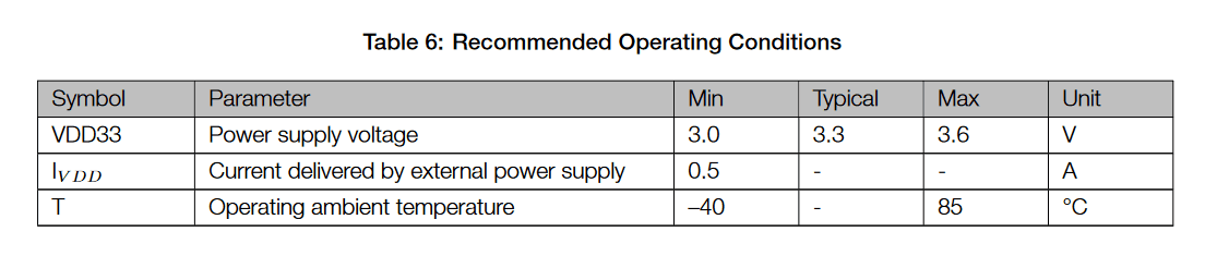
Microcontroler features :
- Operating Voltage: 3.0V~3.6V
- Input Voltage: 7-12V
- Digital I/O Pins (DIO): 25
- Analog Input Pins (ADC): 6
- Analog Outputs Pins (DAC): 2
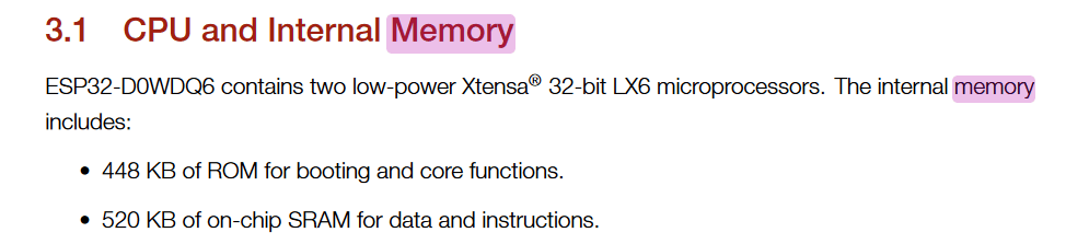
- Flash Memory: 4 MB
- SRAM: 520 KB
- Clock Speed: 240 Mhz
- Perfect for Production: Breadboard-friendly & SMD design, no components on the back
pin out layout


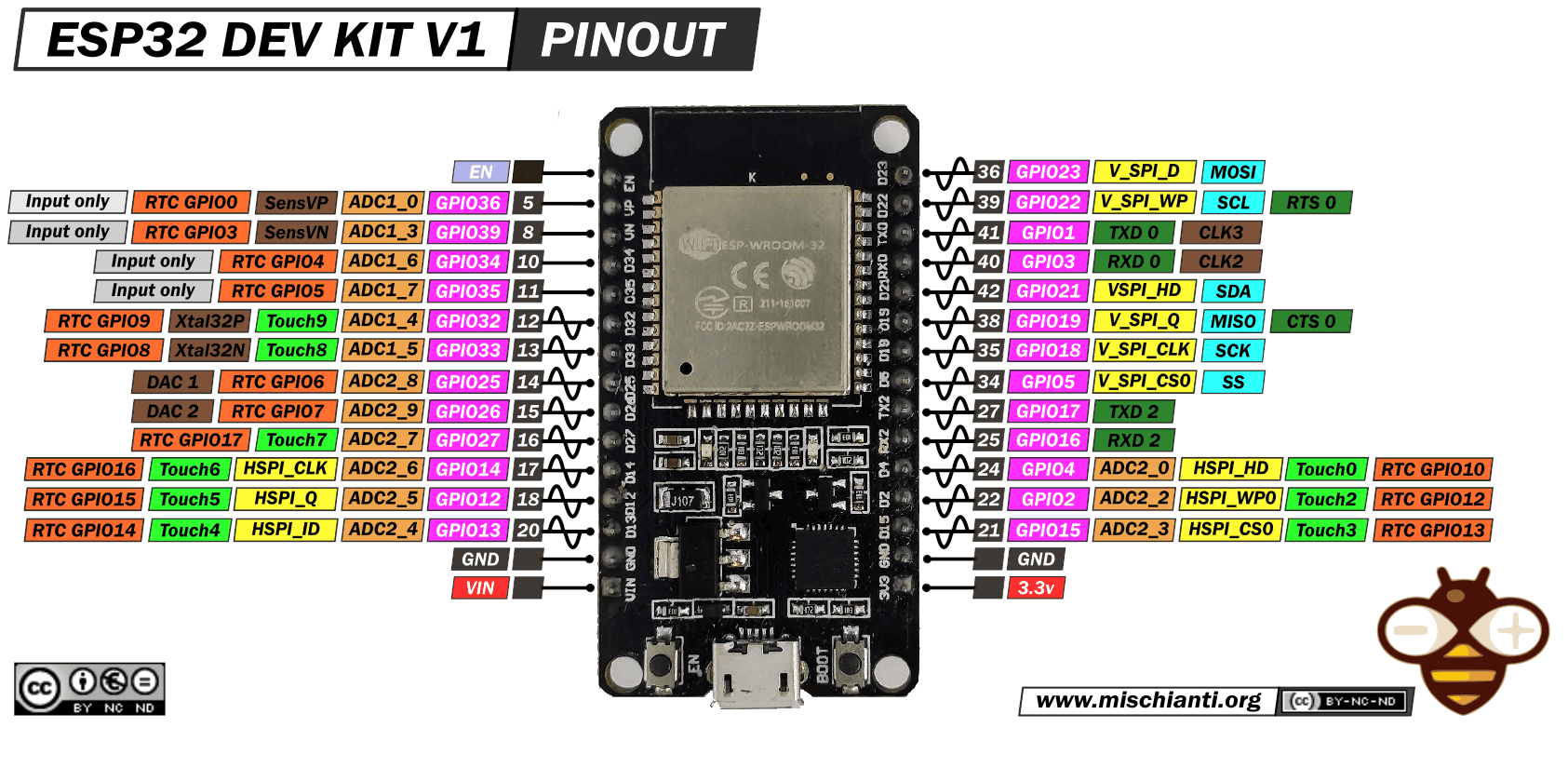
all those information and more you can find it in its data sheet or from this github repo here
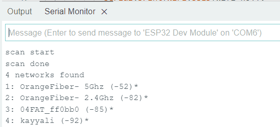
I Follow the instruction from wiki.seeedstudio for using MCU to scan available WiFi networks around me ,so firstly I identify my controller to my Arduino IDE then download the wifi library that contain useful function for this task ,this task is aim to search for the available wifi network around me and print it in serial monitor with its strength value and if it have a password or not
here is the wifi networks that are around me , network with * symbol need password to connect with it and ,the number between () related to its signal strength ,this number called RSSI (Received signal strength indication) that is measured in decibels from 0 (zero) to -120 (minus 120) now when looking at this value the closer to 0 (zero) the stronger the signal is which means it's better
so this code give you wifi information as above and I find out this code at wiki.seeedstudio ,its like below
                #include "WiFi.h"
                void setup()
                {
                  Serial.begin(115200);
                  /* Set WiFi to station mode and
                  disconnect from an AP if it was previously connected
                  */
                  WiFi.mode(WIFI_STA);
                  WiFi.disconnect();
                    delay(100);
                    Serial.println("Setup done");
                }
                void loop()
                {
                  Serial.println("scan start");

                  // WiFi.scanNetworks will return the number of networks found
                  int n = WiFi.scanNetworks();
                  Serial.println("scan done");
                  if (n == 0) {
                    Serial.println("no networks found");
                  } else {
                    Serial.print(n);
                    Serial.println(" networks found");
                    for (int i = 0; i < n; ++i) {
                      // Print SSID and RSSI for each network found
                      Serial.print(i + 1);
                      Serial.print(": ");
                      Serial.print(WiFi.SSID(i));
                      Serial.print(" (");
                      Serial.print(WiFi.RSSI(i));
                      Serial.print(")");
                      Serial.println((WiFi.encryptionType(i) == WIFI_AUTH_OPEN)?" ":"*");
                      delay(10);
                    }
                  }
                  Serial.println("");

                  // Wait a bit before scanning again
                  delay(5000);
                }
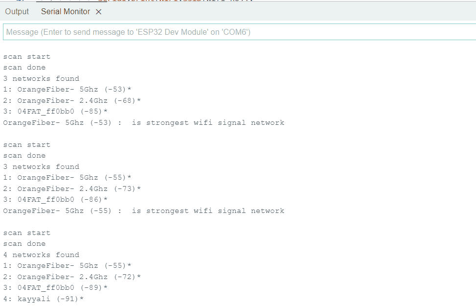
so for me I am intrested to find out the strongest wifi network around me so I modify on the code to print out the strongest wifi network
                #include "WiFi.h"
                int rssi_pre_val=-120;
                int wifi_no=1;
                void setup()
                {
                  Serial.begin(115200);

                  // Set WiFi to station mode and disconnect from an AP if it was previously connected
                  WiFi.mode(WIFI_STA);
                  WiFi.disconnect();
                    delay(100);

                    Serial.println("Setup done");
                }

                void loop()
                {
                  Serial.println("scan start");

                  // WiFi.scanNetworks will return the number of networks found
                  int n = WiFi.scanNetworks();
                  Serial.println("scan done");
                  if (n == 0) {
                    Serial.println("no networks found");
                  } else {
                    Serial.print(n);
                    Serial.println(" networks found");
                    for (int i = 0; i < n; ++i) {
                      // Print SSID and RSSI for each network found
                      Serial.print(i + 1);
                      Serial.print(": ");
                            Serial.print(WiFi.SSID(i));
                            Serial.print(" (");
                            Serial.print(WiFi.RSSI(i));
                            Serial.print(")");
                            Serial.println((WiFi.encryptionType(i) == WIFI_AUTH_OPEN)?" ":"*");
                            /* here i check the rssi value to each network
                            and compare it with rssi_pre_val which will conatin
                            the closest rssi value to zero
                            */
                            if (WiFi.RSSI(i)>rssi_pre_val){
                              //save the value to compare it with the next one
                              rssi_pre_val=WiFi.RSSI(i);
                              // save the wifilist number
                              wifi_no=i;
                            }
                            delay(10);
                        }
                        // print the name of the strongest wifi
                        Serial.print(WiFi.SSID(wifi_no));
                        Serial.print(" (");
                        Serial.print(WiFi.RSSI(wifi_no));
                        Serial.print(")");
                            Serial.print(" : ");
                            Serial.print(" is strongest wifi signal network");
                          }
                          Serial.println("");
                          Serial.println("");

                          // Wait a bit before scanning again
                          delay(5000);
                        }
I try to use the bluetooth connection to control led lighting by using my phone bluetooth connection so I follow this tutorial and try to modify on it,here we will need to use another library called BluetoothSerial.h ,and download an app called "serial bluetooth terminal" on my phone ,
in the code I add another command that make the led blinking ,each line of code have a comment that describe its use , and a video showing the result
                            /*********
                              Rui Santos
                              Complete project details at https://randomnerdtutorials.com
                            *********/

                            // Load libraries
                            #include "BluetoothSerial.h"


                            // Check if Bluetooth configs are enabled
                            #if !defined(CONFIG_BT_ENABLED) || !defined(CONFIG_BLUEDROID_ENABLED)
                            #error Bluetooth is not enabled! Please run `make menuconfig` to and enable it
                            #endif

                            // Bluetooth Serial object
                            BluetoothSerial SerialBT;

                            // GPIO where LED is connected to
                            const int ledPin =  4;


                            // Handle received and sent messages
                            String message = "";
                            char incomingChar;


                            void setup() {
                              pinMode(ledPin, OUTPUT);
                              Serial.begin(115200);
                              // Bluetooth device name
                              SerialBT.begin("ESP32");
                              Serial.println("The device started, now you can pair it with bluetooth!");
                            }

                            void loop() {

                              // Read received messages (LED control command)
                              if (SerialBT.available()){
                                char incomingChar = SerialBT.read();
                                if (incomingChar != '\n'){
                                  message += String(incomingChar);
                                }
                                else{
                                  message = "";
                                }
                                Serial.write(incomingChar);
                              }
                              // Check received message and control output accordingly
                              if (message =="led_on"){
                                // led on
                                digitalWrite(ledPin, HIGH);
                              }
                              // Check received message and control output accordingly
                              else if (message =="led_off"){
                                // led off
                                digitalWrite(ledPin, LOW);
                              }
                              else if (message =="led_blink"){
                                // led blinking 50 times then led on
                                int i=0;
                                while(i<50){
                                digitalWrite(ledPin, HIGH);
                                delay(200);
                                digitalWrite(ledPin, LOW);
                                delay(200);
                                i+=1;
                                }
                                digitalWrite(ledPin, HIGH);

                              }
                              delay(20);
                            }