Week 9: Output Devices
Group Assignments:
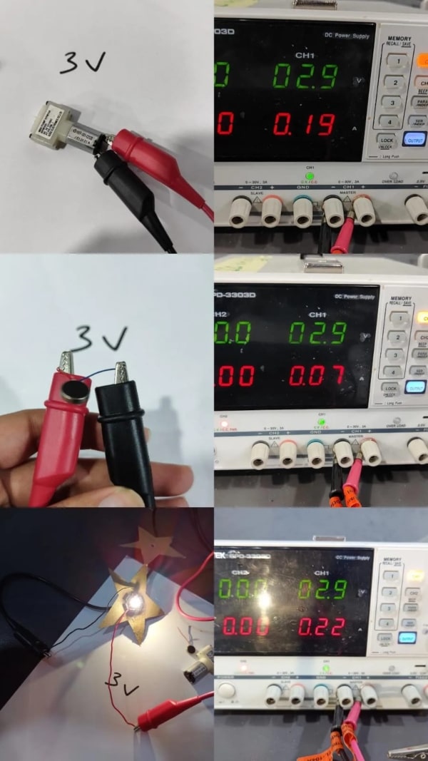
For the group assignment, we are supposed to test some output devices and see how much current they will take. I will start with devices that run on 3 volts.
1.Air pump:
Runs on 2.9 volt and takes .19 Amber, power 2.9*.19 =.551 Watt
2.Vibrator motor:
Runs on 2.9 volt and takes .07 Amber, power 2.9*.07 =.203 Watt
3.Led:
Runs on 2.9 volt and takes .22 Amber, power 2.9*.22 =.638 Watt
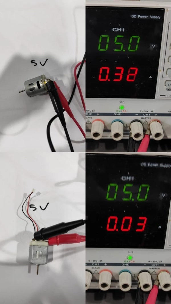
Afterwards, we tested two DC motors which run on 5 volts. The first motor drew 0.03 amperes and consumed 0.15 watts of power, while the second motor drew 0.32 amperes and consumed 1.6 watts of power.
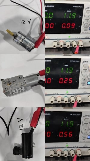
For the last test, we used two DC motors that run on 12 volts. The first motor drew 0.25 amperes and consumed 2.975 watts of power, while the second motor drew 0.09 amperes and consumed 1.071 watts of power.
The third device we tested was a water pump that drew 0.56 amperes and consumed 6.664 watts of power.
The formula used to calculate power is P=VI, where P represents power, V represents voltage, and I represents current.
In conclusion, our tests revealed varying power requirements among the tested output devices. The power consumption depended on factors such as voltage, current draw, and the specific characteristics of each device. By understanding these power characteristics, we can make informed decisions when designing circuits and selecting power sources for our projects.
Individual Assignments:
During the Output Device Week, I focused on incorporating an output device into my microcontroller board and programming it for specific tasks. For my project, I decided to control a motor using a microcontroller (MCU) as the output device.
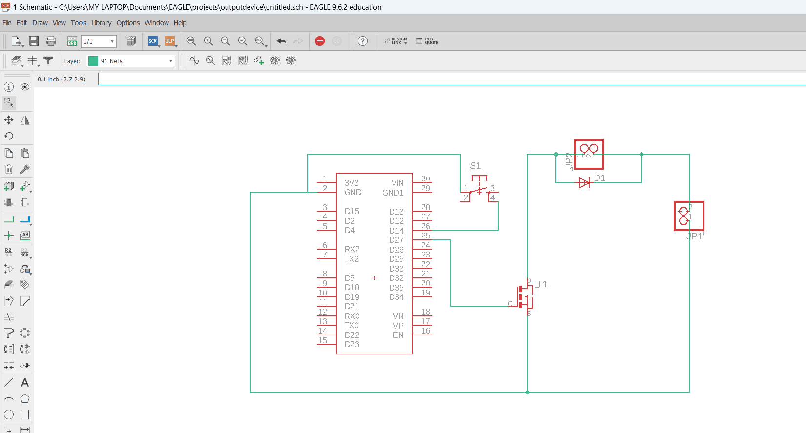
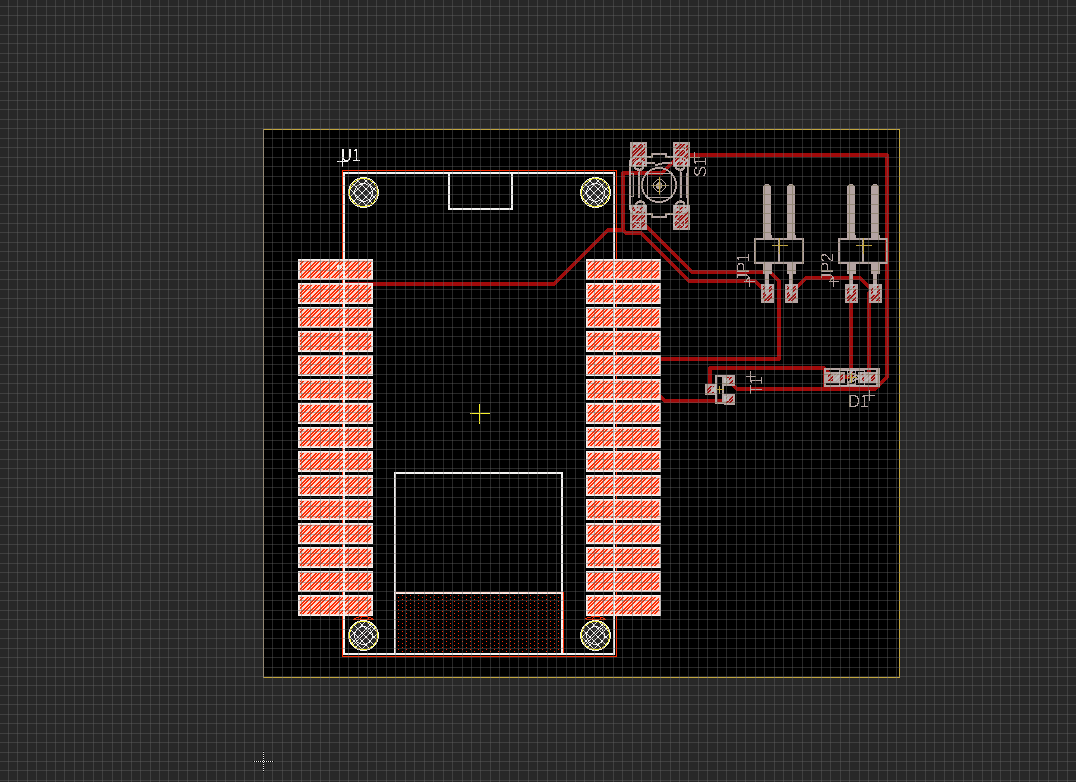
To begin, I designed the circuit schematic and layout using Eagle software, allowing me to visualize component connections and their placement on the board.
One challenge I encountered was that the motor required a higher voltage than the microcontroller's output pins could provide. To overcome this, I integrated a MOSFET into my circuit design. This MOSFET acted as a switch, allowing me to regulate the connection between the motor and an external power source, such as a battery. By controlling the MOSFET's gate signal with the microcontroller's output pin, I could turn the motor on or off.
After finalizing the design, I proceeded to fabricate the physical circuit board using a Roland PCB machine. This machine precisely cut and engraved the board based on my design specifications.
The last step involved soldering the components onto the fabricated PCB. This required careful and precise soldering techniques to ensure proper connections and functionality. By completing this step, the motor was fully integrated into the microcontroller board.
Circuit Component and description
In my project, I utilized the following components: the DOIT ESP32 DEVKIT microcontroller (MCU), a MOSFET, a push button, and a battery and a dc motor.
The DOIT ESP32 DEVKIT MCU served as the central control unit for my project. It provided the necessary processing power and capabilities to control and interact with other components. The MCU acted as the brain of the system, executing programmed instructions and facilitating communication between different parts of the circuit.
To overcome the voltage compatibility issue between the MCU's output pin and the motor's power requirements, I incorporated a MOSFET into the circuit. The MOSFET allowed me to control the connection between the motor and an external power source, which in this case was a battery. By using the MOSFET, I could regulate the motor's power supply independently from the MCU, ensuring proper voltage levels for motor operation.
Additionally, I integrated a push button into the circuit. This button served as an input device, allowing for user interaction and control. The MCU would detect button presses and trigger specific actions or functions accordingly.
Finally, the battery provided the necessary power source for the circuit. It supplied the voltage required to operate the motor and power the MCU and other components.
DOIT esp32 DEVKIT Microcontroler features :
- Operating Voltage: 3.0V~3.6V
- Input Voltage: 7-12V
- Digital I/O Pins (DIO): 25
- Analog Input Pins (ADC): 6
- Analog Outputs Pins (DAC): 2
- Flash Memory: 4 MB
- SRAM: 520 KB
- Clock Speed: 240 Mhz
- Perfect for Production: Breadboard-friendly & SMD design, no components on the back
pin out layout


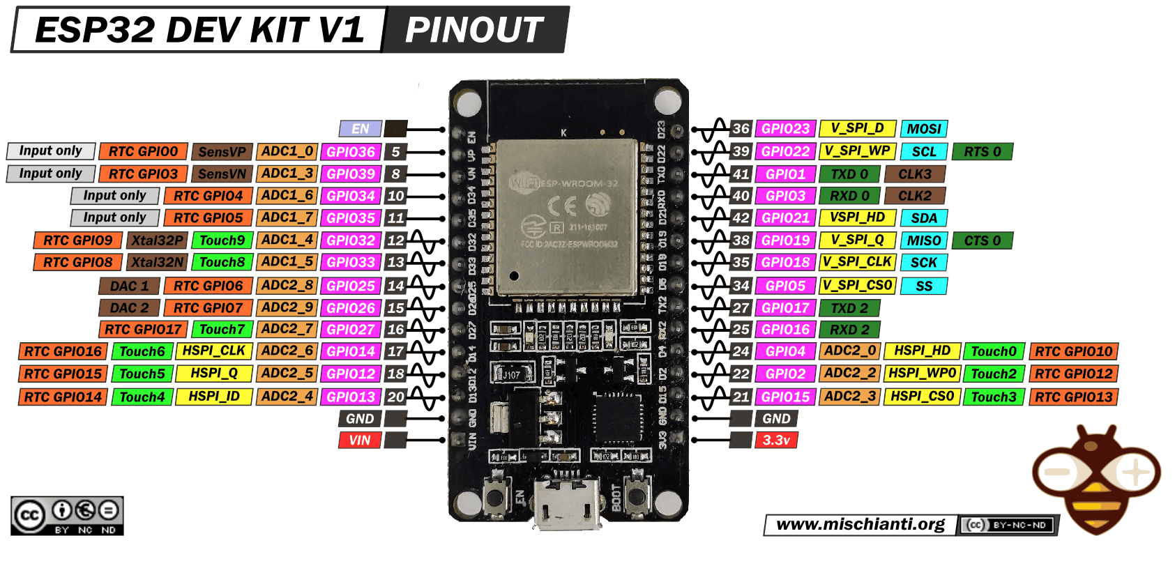
all those information and more you can find it in its data sheet or from this github repo here
Circuit design and Fabrication
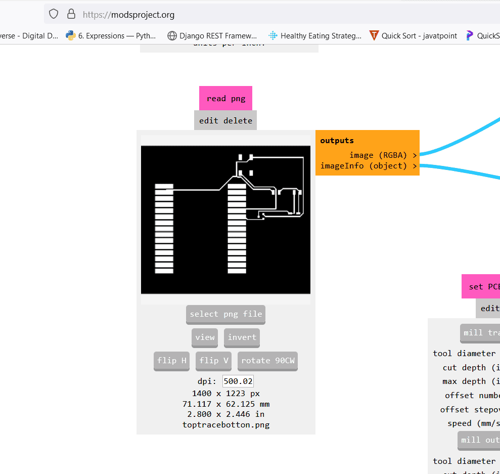
For the circuit design phase, I used Eagle software to create the schematic and plan the layout of components. To generate the G-code for PCB fabrication, I relied on the MODS Project platform. After extracting a PNG image from the design, I colored it using black for cutting areas and white for preservation.
For PCB fabrication, I utilized the Roland SRM-20 PCB machine, known for its precision and reliability. Using the G-code generated from the MODS Project, the Roland SRM-20 accurately cut and engraved the circuit board material, ensuring proper alignment of traces and components.
Eagle schematic
Eagle board
Modes code generation for trace and cut outline
z calibration for the pcb machine
Roland Pcb machine

solder the component
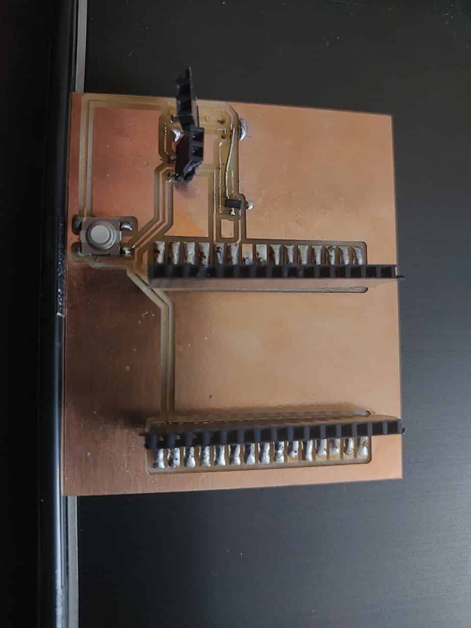
Programming
In the programming aspect of my project, I used the Arduino IDE to write and upload code to the microcontroller. The code was designed to control the DC motor based on the state of a push button.
            int transistor_pin = 27 ; //initializing pin 2 as pwm
            int push_pin = 14 ;
            int state_push = 0;


            void setup() {
              // put your setup code here, to run once:
              Serial.begin(9600);
              pinMode(transistor_pin, OUTPUT);
              pinMode(push_pin,INPUT_PULLUP);

            }

            void loop() {
              state_push=digitalRead(push_pin);

              if (state_push==LOW){
                digitalWrite(transistor_pin,HIGH);
              }
              else{
                digitalWrite(transistor_pin,LOW);
              }

            Serial.println(state_push);
            delay(100);
            }
In the setup() function, I initialized the serial communication and configured the pins for the transistor and push button. The transistor_pin was set as an output to control the motor, while the push_pin was set as an input with a pull-up resistor to detect the state of the push button.
The main logic is implemented in the loop() function. It reads the state of the push button using digitalRead() and stores the value in the state_push variable. If the button is pressed (state_push is LOW), it sets the transistor_pin to HIGH, turning on the transistor and activating the motor. Otherwise, if the button is not pressed, it sets the transistor_pin to LOW, turning off the transistor and stopping the motor.
The code also prints the state of the push button to the serial monitor using Serial.println() and adds a small delay of 100 milliseconds between iterations of the loop to prevent rapid button presses from being registered multiple times.
This code allows the DC motor to be controlled by pressing the push button, providing a simple on/off functionality.
.svg)

