Week 12: Networking and Communications
Group Assignments:
Introduction
During Networking and Communications Week in Fab Academy, we embarked on a project to explore various methods of connecting two microcontrollers. Our objective was to establish a wireless communication link between microcontrollers and utilize it to control a LED lighting system. In this documentation, we will focus on our exploration of ESP-NOW, a communication protocol developed by Espressif Systems, and demonstrate how we successfully implemented it in our project.
Exploring ESP-NOW
ESP-NOW is a communication protocol specifically designed for low-power devices, developed by Espressif Systems, the creators of ESP32 microcontrollers. It allows direct communication between devices without the need for a Wi-Fi network or an access point. ESP-NOW operates in two modes: Station (STA) and Soft Access Point (AP).
Implementation
- Hardware Setup: We connected an ESP32 Dev Kit microcontroller to a push button and a LED. The push button was used as an input to trigger the LED lighting control. Additionally, we had another microcontroller, acting as the receiver, connected to an NeoPixel LED.
- Configuring ESP-NOW: We set up one ESP32 module as a sender and the other as a receiver. The sender module was configured to send messages via ESP-NOW when the push button was pressed, while the receiver module was set up to receive and interpret these messages.
- Establishing Communication: The sender module, in STA mode, established a direct connection with the receiver module, operating in AP mode. This allowed for peer-to-peer communication between the two microcontrollers.
- LED Lighting Control: When the push button was pressed on the sender module, it sent a message via ESP-NOW to the receiver module. The receiver module interpreted the message and controlled the connected LED accordingly, resulting in the desired lighting effect.
receiver
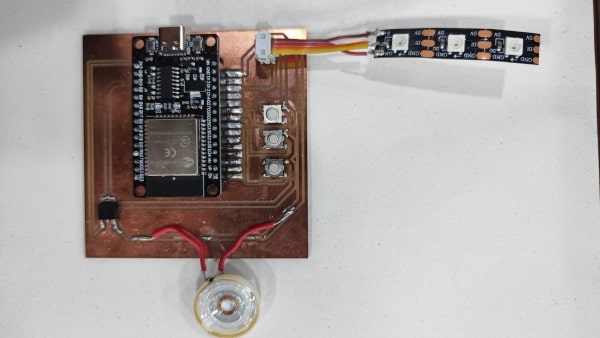
remote
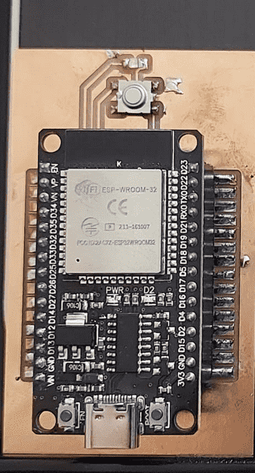
for the remote and receiver we need to figure out the mac number its like an identifire for each mcu
          #include "WiFi.h"

          void setup(){
            Serial.begin(115200);
            WiFi.mode(WIFI_MODE_STA);
            Serial.println(WiFi.macAddress());
          }

          void loop(){

          }
.png)
remote code
            #include WiFi.h
            #include esp_now.h

            uint8_t remoteMac[] = {0xB8, 0xD6, 0x1A, 0x47, 0x9A, 0x64};

            const int buttonPin = 12; // GPIO 5

            void setup() {
              Serial.begin(115200);
              pinMode(buttonPin, INPUT_PULLUP);
              WiFi.mode(WIFI_STA);
              WiFi.disconnect();
              if (esp_now_init() != ESP_OK) {
                Serial.println("Error initializing ESP-NOW");
                return;
              }
              esp_now_peer_info_t peerInfo;
              memcpy(peerInfo.peer_addr, remoteMac, 6);
              peerInfo.channel = 0;
              peerInfo.encrypt = false;
              if (esp_now_add_peer(&peerInfo) != ESP_OK) {
                Serial.println("Failed to add peer");
                return;
              }
            }

            void loop() {
              if (digitalRead(buttonPin) == HIGH) {
                uint8_t dataToSend = 1;
                Serial.print("Data Sent: ");
                Serial.println(dataToSend);
                esp_err_t result = esp_now_send(remoteMac, &dataToSend, sizeof(dataToSend));
                if (result == ESP_OK) {
                  Serial.println("Data sent successfully");
                } else {
                  Serial.println("Error sending data");
                }
                delay(10);
              } else {
                uint8_t dataToSend = 0;
                Serial.print("Data Sent: ");
                Serial.println(dataToSend);
                esp_err_t result = esp_now_send(remoteMac, &dataToSend, sizeof(dataToSend));
                if (result == ESP_OK) {
                  Serial.println("Data sent successfully");
                } else {
                  Serial.println("Error sending data");
                }
                delay(10);
              }
            }
receiver code
          #include WiFi.h
            #include esp_now.h
            #include Adafruit_NeoPixel.h

            #define PIN_NEO_PIXEL  13  // Arduino pin that connects to NeoPixel
            #define NUM_PIXELS     3   // The number of LEDs (pixels) on NeoPixel

            Adafruit_NeoPixel NeoPixel(NUM_PIXELS, PIN_NEO_PIXEL, NEO_GRB + NEO_KHZ800);

            uint8_t remoteMac[] = {0xB8, 0xD6, 0x1A, 0x5C, 0x03, 0x88};

            void setup() {
              Serial.begin(115200);
              NeoPixel.begin();
              NeoPixel.clear(); // Set all pixel colors to 'off'
              NeoPixel.show();  // Update the NeoPixel strip

              WiFi.mode(WIFI_STA);
              WiFi.disconnect();

              if (esp_now_init() != ESP_OK) {
                Serial.println("Error initializing ESP-NOW");
                return;
              }

              esp_now_peer_info_t peerInfo;
              memset(&peerInfo, 0, sizeof(peerInfo));
              memcpy(peerInfo.peer_addr, remoteMac, sizeof(remoteMac));
              peerInfo.channel = 0;
              peerInfo.encrypt = false;

              if (esp_now_add_peer(&peerInfo) != ESP_OK) {
                Serial.println("Failed to add peer");
                return;
              }

              esp_now_register_recv_cb(OnDataRecv);
            }

            void loop() {
              // No need to add any code here
            }

            void OnDataRecv(const uint8_t* mac, const uint8_t* data, int len) {
              if (len == 1) {
                uint8_t receivedData = data[0];
                handleReceivedData(receivedData);
              }
            }

            void handleReceivedData(uint8_t data) {
              if (data == 0) {
                NeoPixel.clear();
                NeoPixel.show();
              } else if (data == 1) {
                NeoPixel.setPixelColor(0, NeoPixel.Color(255, 0, 0));
                NeoPixel.show();
                delay(2000);
                NeoPixel.clear();
                NeoPixel.show();
              } else if (data == 2) {
                NeoPixel.setPixelColor(1, NeoPixel.Color(125, 125, 0));
                NeoPixel.show();
                delay(2000);
                NeoPixel.clear();
                NeoPixel.show();
              } else if (data == 3) {
                NeoPixel.setPixelColor(2, NeoPixel.Color(125, 80, 200));
                NeoPixel.show();
                delay(2000);
                NeoPixel.clear();
                NeoPixel.show();
              }
            }
Conclusion
Through our exploration of ESP-NOW, we successfully established a wireless communication link between microcontrollers, enabling us to control a LED lighting system. ESP-NOW provided a straightforward and efficient method for peer-to-peer communication without relying on Wi-Fi infrastructure. This project showcases the versatility and potential of ESP-NOW for various applications requiring wireless microcontroller communication.
Individual Assignments:
As a general introduction for this topic :there are two type of communication wired and wireless ; Wired communication refers to the transmission of data between devices through a physical connection, typically through cables or wires. Examples of wired communication include Ethernet, USB, and HDMI cables. Wired communication is often used in situations where a reliable and stable connection is required, as well as in applications where security and privacy are important.
Wireless communication, on the other hand, uses electromagnetic waves to transmit data between devices without the need for a physical connection. Examples of wireless communication include Wi-Fi, Bluetooth, and cellular networks. Wireless communication is often used in situations where mobility and flexibility are important, such as in portable devices, smart homes, and Internet of Things (IoT) applications.
While both wired and wireless communication have their advantages and disadvantages, they are often used in different contexts depending on the specific needs of the application. Wired communication typically offers faster and more reliable data transfer, but requires physical connections and can be more difficult to set up. Wireless communication offers more flexibility and mobility, but can be subject to interference and can sometimes be less reliable.
(source chatGPT)
In this week I need to design, build, and connect wired or wireless node(s)
with network or bus addresses , so I try to use low energy bluetooth connection to connect to MCU to make specific task ,
component I use : ESP32 dev kit , XIAO ESP32C3 , push button , led and buzzer ,I will use Arduino Ide to programme my circuit
As i say before I used a Bluetooth low energy (BLE) connection to establish a wireless link between my microcontrollers . This technology has gained popularity due to its low power consumption and ease of use, making it ideal for applications where battery life is critical. In this document, I will detail requirements, process, and results for my experience .
Circuit design and fabrication
As a first step for me that I Design two circuit schematic using a Eagle software . one contain led and push button and the other one contain led and buzzer and I add a light sensor just in order to try it ,
I faced a problem in the PCB design since I could not find an SMD footprint for the XIO ESP32C microcontroller. The only one I found online was a footprint with hole connections,
which would not work for my project. However, I learned that I can change the footprint design in Eagle. To do this, I followed a documentation guide created by my colleagues which was very helpful.
I was able to modify the existing footprint by deleting the existing pads and adding new ones in the desired location and configuration.
I call this a master board which will act as a server ,it will be like a remote
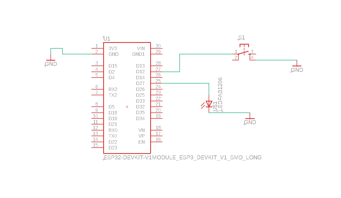
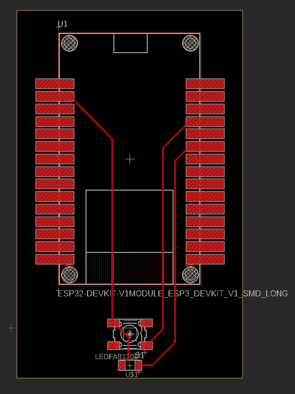
I call this a receiver board which will act as a client ,it will have the noisy stuff
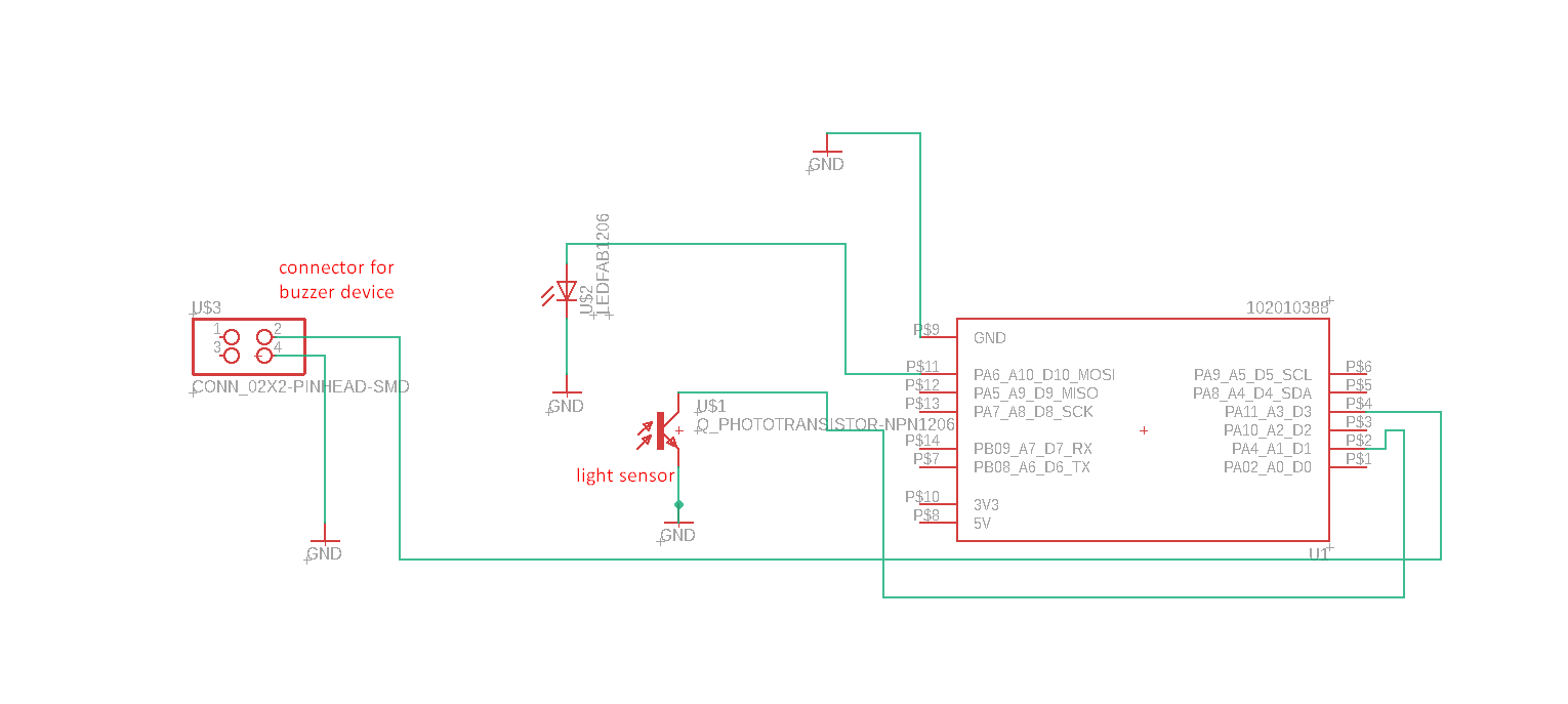
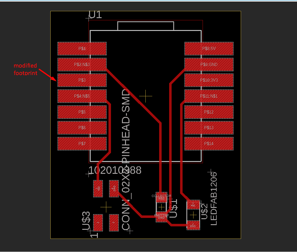
Explain the server and client meaning and how the flow of communication will be
Overview
In this project, we utilized Bluetooth Low Energy (BLE) communication to establish a network between two microcontrollers: a server and a client. The objective was to make a buzzer emit sound when a push button connected to the server microcontroller was clicked.
Server (Microcontroller 1)
The server microcontroller plays the role of the device that initiates the communication. It is connected to a push button, which generates a signal when clicked. When the server microcontroller detects this event, it transmits a message over the BLE connection.
Client (Microcontroller 2)
The client microcontroller acts as the device that receives the message from the server. It is connected to a buzzer, which will emit sound based on the received message. When the client microcontroller receives the message from the server indicating a push button click, it triggers the buzzer to emit sound.
Communication Flow
- Initialization: The server and client microcontrollers are set up and configured for BLE communication. The client microcontroller prepares to receive messages, while the server microcontroller waits for the push button event.
- Push Button Event: When the push button connected to the server microcontroller is clicked, it generates a signal or event.
- Message Transmission: The server microcontroller detects the push button event and sends a message over the established BLE connection to the client microcontroller.
- Message Reception: The client microcontroller receives the message from the server microcontroller.
- Buzzer Activation: Upon receiving the message indicating the push button click, the client microcontroller activates the buzzer, resulting in the emission of sound.
By utilizing BLE communication between the server and client microcontrollers, you have successfully achieved wireless control of the buzzer, allowing it to emit sound when the push button is clicked on the server microcontroller.
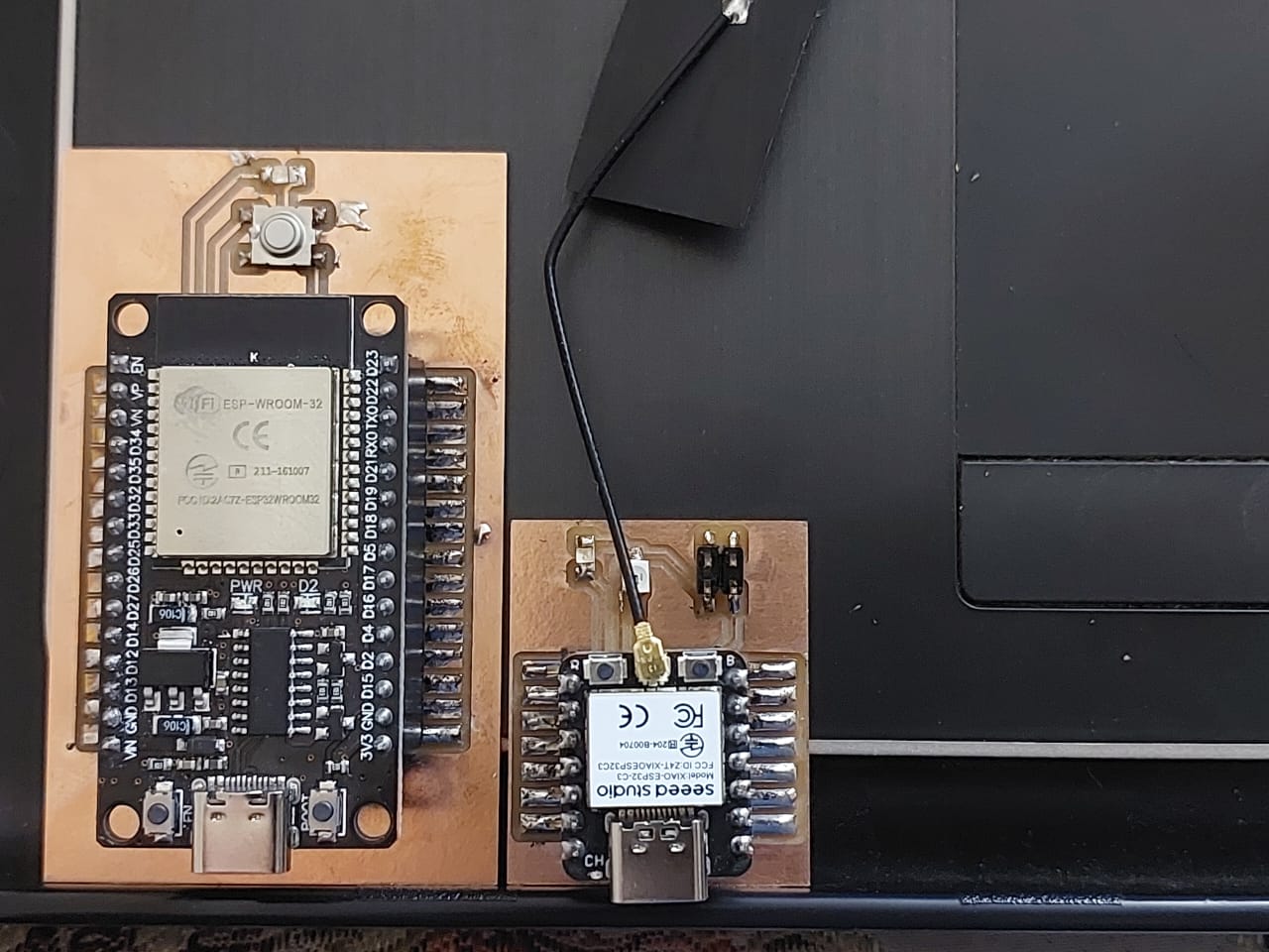
now I will go with production and i will cut my board then start the soldering process ,
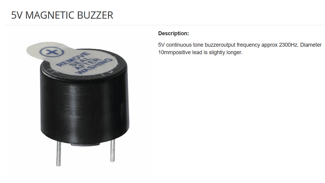
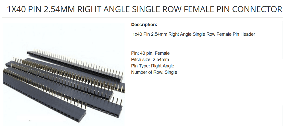
component that I use ,

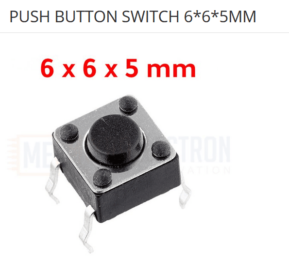
for mcu connection
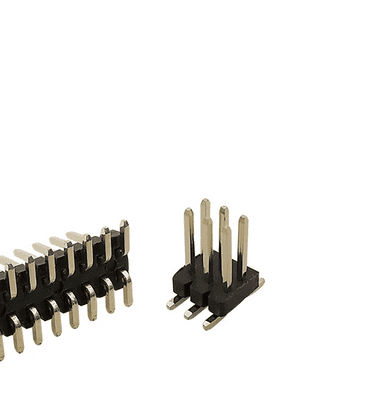
for buzzer connection
pcb production


soldering stage ,One of the most important tricks to ensure a good solder joint is to heat both the board and the component to be soldered at the same time. This helps the solder flow evenly and creates a strong bond. Another useful trick is to put a very small amount of soldering wire on the board in the location where the component will be placed. This can help the component stick to the board before adding more soldering material. These tips can help ensure a successful soldering process and a reliable final product

Now, I will go to programming part ,I will use the bluetooth library that is newly add to esp32 library so no need to install any library ,and if you install a bluetooth library again by mistake it will generate an error when you compiled the code that there is two path for that library so you need to uninstall it ,and that is the first problem that face me .
to use the library efficiently you should understand how the data transfer from client to server and in which shape
As a basic information to understand is that BLE clients and servers devices transmit and receive data through Generic Attribute Profile (GATT).
In this protocol, the central devices act as clients and any peripheral device is the server. The server has Characteristics, Services, and a particular ATT table that is used in the transmission and reception of data. The GATT protocol consists of a hierarchy in which there are different sections known as Profiles, Services, and Characteristics ,each service and Characteristics have a unique uuid which like a key that help to identify the characteristic and help when you want to connect a client to a specific service
the most important part is the service and its Characteristics, Every service has its own Characteristics. These are broken down into a single Characteristic or several Characteristics. They also have unique UUIDs. These contain all the useful information in its value section.
a useful resource that you can read : youtube list ,a BLE library documentation and a code example using BLE library here
server side code
                /*
                Video: https://www.youtube.com/watch?v=oCMOYS71NIU
                Based on Neil Kolban example for IDF:
                https://github.com/nkolban/esp32-snippets/blob/master/cpp_utils/tests/BLE%20Tests/SampleNotify.cpp
                Ported to Arduino ESP32 by Evandro Copercini
                updated by chegewara
              Create a BLE server that, once we receive a connection, will send periodic notifications.
              The service advertises itself as: 4fafc201-1fb5-459e-8fcc-c5c9c331914b
              And has a characteristic of: beb5483e-36e1-4688-b7f5-ea07361b26a8
              The design of creating the BLE server is:
              1. Create a BLE Server
              2. Create a BLE Service
              3. Create a BLE Characteristic on the Service
              4. Create a BLE Descriptor on the characteristic
              5. Start the service.
              6. Start advertising.
              A connect hander associated with the server starts a background task that performs notification
              every couple of seconds.
                */
                #include
                #include
                #include
                #include
                //server value
                BLEServer* pServer = NULL;
                //characeristic value
                BLECharacteristic* pCharacteristic = NULL;

                bool deviceConnected = false;
                bool oldDeviceConnected = false;
                uint32_t value = 0;
                int ahmad=1;
                int led_pin=27;

                // See the following for generating UUIDs:
                // https://www.uuidgenerator.net/

                #define SERVICE_UUID        "4fafc201-1fb5-459e-8fcc-c5c9c331914b"
                #define CHARACTERISTIC_UUID "beb5483e-36e1-4688-b7f5-ea07361b26a8"
                #define BUTTON_PIN 12

                class MyServerCallbacks: public BLEServerCallbacks {
                    void onConnect(BLEServer* pServer) {
                      deviceConnected = true;
                    };

                    void onDisconnect(BLEServer* pServer) {
                      deviceConnected = false;
                    }
                };


                void setup() {
                  Serial.begin(115200);
                  //push button
                  pinMode(BUTTON_PIN, INPUT_PULLUP);
                  pinMode(led_pin, OUTPUT);
                  // Create the BLE Device
                  BLEDevice::init("ESP32");

                  // Create the BLE Server
                  pServer = BLEDevice::createServer();
                  pServer->setCallbacks(new MyServerCallbacks());

                  // Create the BLE Service
                  BLEService *pService = pServer->createService(SERVICE_UUID);

                  // Create a BLE Characteristic
                  pCharacteristic = pService->createCharacteristic(
                                      CHARACTERISTIC_UUID,
                                      BLECharacteristic::PROPERTY_READ   |
                                      BLECharacteristic::PROPERTY_WRITE  |
                                      BLECharacteristic::PROPERTY_NOTIFY |
                                      BLECharacteristic::PROPERTY_INDICATE
                                    );

                  //pointer
                  BLE2902 *pBLE2902;
                  pBLE2902 = new BLE2902();
                  pBLE2902->setNotifications(true);
                  // Create a BLE Descriptor
                  pCharacteristic->addDescriptor(pBLE2902);
                  // pCharacteristic->addDescriptor(new BLE2902()); here it is a bluetooth general descriptor
                  // pCharacteristic->addDescriptor(new BLE2902());

                  // Start the service
                  pService->start();

                  // Start advertising
                  BLEAdvertising *pAdvertising = BLEDevice::getAdvertising();
                  pAdvertising->addServiceUUID(SERVICE_UUID);
                  pAdvertising->setScanResponse(false);
                  pAdvertising->setMinPreferred(0x0);  // set value to 0x00 to not advertise this parameter
                  BLEDevice::startAdvertising();
                  Serial.println("Waiting a client connection to notify...");
                }

                void loop() {
                    // notify changed value
                    if (deviceConnected) {
                        ahmad=digitalRead(BUTTON_PIN);
                        if(ahmad==0){
                          digitalWrite(led_pin,HIGH);
                        }
                        else{
                          digitalWrite(led_pin,LOW);
                        }
                        pCharacteristic->setValue(ahmad);

                        //notify client that value is changed
                        pCharacteristic->notify();
                        // bluetooth stack will go into congestion,
                        //if too many packets are sent, in 6 hours test i was able to go as low as 3ms
                        delay(1000);
                    }
                    // disconnecting
                    if (!deviceConnected && oldDeviceConnected) {
                        delay(500); // give the bluetooth stack the chance to get things ready
                        pServer->startAdvertising(); // restart advertising
                        Serial.println("start advertising");
                        oldDeviceConnected = deviceConnected;
                    }
                    // connecting
                    if (deviceConnected && !oldDeviceConnected) {
                        // do stuff here on connecting
                        oldDeviceConnected = deviceConnected;
                    }
                }
client side code that i program the xio-esp32c with
                  /**
                  * A BLE client example that is rich in capabilities.
                  * There is a lot new capabilities implemented.
                  * author unknown
                  * updated by chegewara and MoThunderz
                  */

                  #include "BLEDevice.h"
                  //#include "BLEScan.h"

                  //define led and buzzer pins
                  #define led_pin 10
                  #define piezo 5

                  uint32_t counterpointer=3;

                  // Define UUIDs:
                  static BLEUUID serviceUUID("4fafc201-1fb5-459e-8fcc-c5c9c331914b");
                  static BLEUUID    charUUID_1("beb5483e-36e1-4688-b7f5-ea07361b26a8");
                  static BLEUUID    charUUID_2("beb5483e-36e1-4688-b7f5-ea07361b26a8");

                  // Some variables to keep track on device connected
                  static boolean doConnect = false;
                  static boolean connected = false;
                  static boolean doScan = false;

                  // Define pointer for the BLE connection
                  static BLEAdvertisedDevice* myDevice;
                  BLERemoteCharacteristic* pRemoteChar_1;
                  BLERemoteCharacteristic* pRemoteChar_2;

                  // Callback function for Notify function
                  static void notifyCallback(BLERemoteCharacteristic* pBLERemoteCharacteristic,
                                              uint8_t* pData,
                                              size_t length,
                                              bool isNotify) {
                    if(pBLERemoteCharacteristic->getUUID().toString() == charUUID_1.toString()) {

                      // convert received bytes to integer
                      uint32_t counter = pData[0];
                      for(int i = 1; igetAddress().toString().c_str());

                    BLEClient*  pClient  = BLEDevice::createClient();
                    Serial.println(" - Created client");

                    pClient->setClientCallbacks(new MyClientCallback());

                    // Connect to the remove BLE Server.
                    pClient->connect(myDevice);  // if you pass BLEAdvertisedDevice instead of address,
                    //it will be recognized type of peer device address (public or private)
                    Serial.println(" - Connected to server");

                    // Obtain a reference to the service we are after in the remote BLE server.
                    BLERemoteService* pRemoteService = pClient->getService(serviceUUID);
                    if (pRemoteService == nullptr) {
                      Serial.print("Failed to find our service UUID: ");
                      Serial.println(serviceUUID.toString().c_str());
                      pClient->disconnect();
                      return false;
                    }
                    Serial.println(" - Found our service");

                    connected = true;
                    pRemoteChar_1 = pRemoteService->getCharacteristic(charUUID_1);
                    pRemoteChar_2 = pRemoteService->getCharacteristic(charUUID_2);
                    // if(connectCharacteristic(pRemoteService, pRemoteChar_1) == false)
                    //   connected = false;
                    if(connectCharacteristic(pRemoteService, pRemoteChar_2) == false)
                      connected = false;

                    if(connected == false) {
                      pClient-> disconnect();
                      Serial.println("At least one characteristic UUID not found");
                      return false;
                    }
                    return true;
                  }

                  // Function to chech Characteristic
                  bool connectCharacteristic(BLERemoteService* pRemoteService, BLERemoteCharacteristic* l_BLERemoteChar) {
                    // Obtain a reference to the characteristic in the service of the remote BLE server.
                    if (l_BLERemoteChar == nullptr) {
                      Serial.print("Failed to find one of the characteristics");
                      Serial.print(l_BLERemoteChar->getUUID().toString().c_str());
                      return false;
                    }
                    Serial.println(" - Found characteristic: " + String(l_BLERemoteChar->getUUID().toString().c_str()));

                    if(l_BLERemoteChar->canNotify())
                      l_BLERemoteChar->registerForNotify(notifyCallback);

                    return true;
                  }

                  // Scan for BLE servers and find the first one that advertises the service we are looking for.
                  class MyAdvertisedDeviceCallbacks: public BLEAdvertisedDeviceCallbacks {
                    //Called for each advertising BLE server.
                    void onResult(BLEAdvertisedDevice advertisedDevice) {
                      Serial.print("BLE Advertised Device found: ");
                      Serial.println(advertisedDevice.toString().c_str());

                      // We have found a device, let us now see if it contains the service we are looking for.
                      if (advertisedDevice.haveServiceUUID() && advertisedDevice.isAdvertisingService(serviceUUID)) {

                        BLEDevice::getScan()->stop();
                        myDevice = new BLEAdvertisedDevice(advertisedDevice);
                        doConnect = true;
                        doScan = true;

                      } // Found our server
                    } // onResult
                  }; // MyAdvertisedDeviceCallbacks

                  void setup() {
                    Serial.begin(115200);
                    pinMode(led_pin,OUTPUT);
                    Serial.println("Starting Arduino BLE Client application...");
                    BLEDevice::init("");

                    // Retrieve a Scanner and set the callback we want to use to be informed when we
                    // have detected a new device.  Specify that we want active scanning and start the
                    // scan to run for 5 seconds.
                    BLEScan* pBLEScan = BLEDevice::getScan();
                    pBLEScan->setAdvertisedDeviceCallbacks(new MyAdvertisedDeviceCallbacks());
                    pBLEScan->setInterval(1349);
                    pBLEScan->setWindow(449);
                    pBLEScan->setActiveScan(true);
                    pBLEScan->start(5, false);
                  } // End of setup.

                  void loop() {

                    // If the flag "doConnect" is true then we have scanned for and found the desired
                    // BLE Server with which we wish to connect.  Now we connect to it.  Once we are
                    // connected we set the connected flag to be true.
                    if (doConnect == true) {
                      if (connectToServer()) {
                        Serial.println("We are now connected to the BLE Server.");
                      } else {
                        Serial.println("We have failed to connect to the server; there is nothin more we will do.");
                      }
                      doConnect = false;
                    }

                    // If we are connected to a peer BLE Server, update the characteristic each time we are reached
                    // with the current time since boot.
                    if (connected) {
                      std::string rxValue = pRemoteChar_2->readValue();
                      Serial.print("Characteristic 2 (readValue): ");
                      Serial.println(rxValue.c_str());


                      String txValue = "String with random value from client: " + String(-random(1000));
                      Serial.println("Characteristic 2 (writeValue): " + txValue);

                      // Set the characteristic's value to be the array of bytes that is actually a string.
                      pRemoteChar_2->writeValue(txValue.c_str(), txValue.length());
                      if (counterpointer==0){
                          digitalWrite(led_pin,OUTPUT);
                          Serial.println("helooooooooooooooo");
                          Serial.println(digitalRead(led_pin));
                          tone(piezo, 1000); // Send 1KHz sound signal...
                          delay(1000);        // ...for 1 sec
                          noTone(piezo);     // Stop sound...
                          delay(1000);        // ...for 1sec
                      }else{
                        digitalWrite(led_pin,LOW);
                      }
                    }else if(doScan){
                      BLEDevice::getScan()->start(0);
                      // this is just example to start scan after disconnect,
                      //most likely there is better way to do it in arduino
                    }

                    // In this example "delay" is used to delay with one second. This is of course a very basic
                    // implementation to keep things simple. I recommend to use millis() for any production code
                    delay(1000);
                  }
.svg)

