.svg)


week 3
In this week I learn with my colleagues the specification for our lab laser cutter and we find the best cutting settings for number of materials like MDF and Acrylic and find out the kerf of our laser cutter machine and the best fitting joint
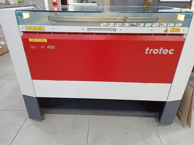
our machine trotec laser cutter
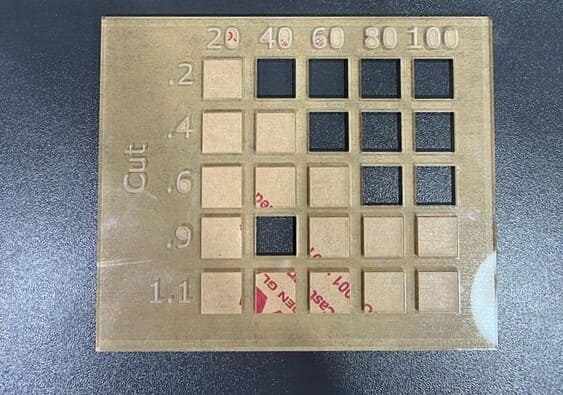
To characterize the laser cutting machine, we make four test cut,engrave,kerf and joint tests on different materials with different test, so first to start the cut test we made the design below on fusion 360 then prepare it by Inkscape to color it for the laser:
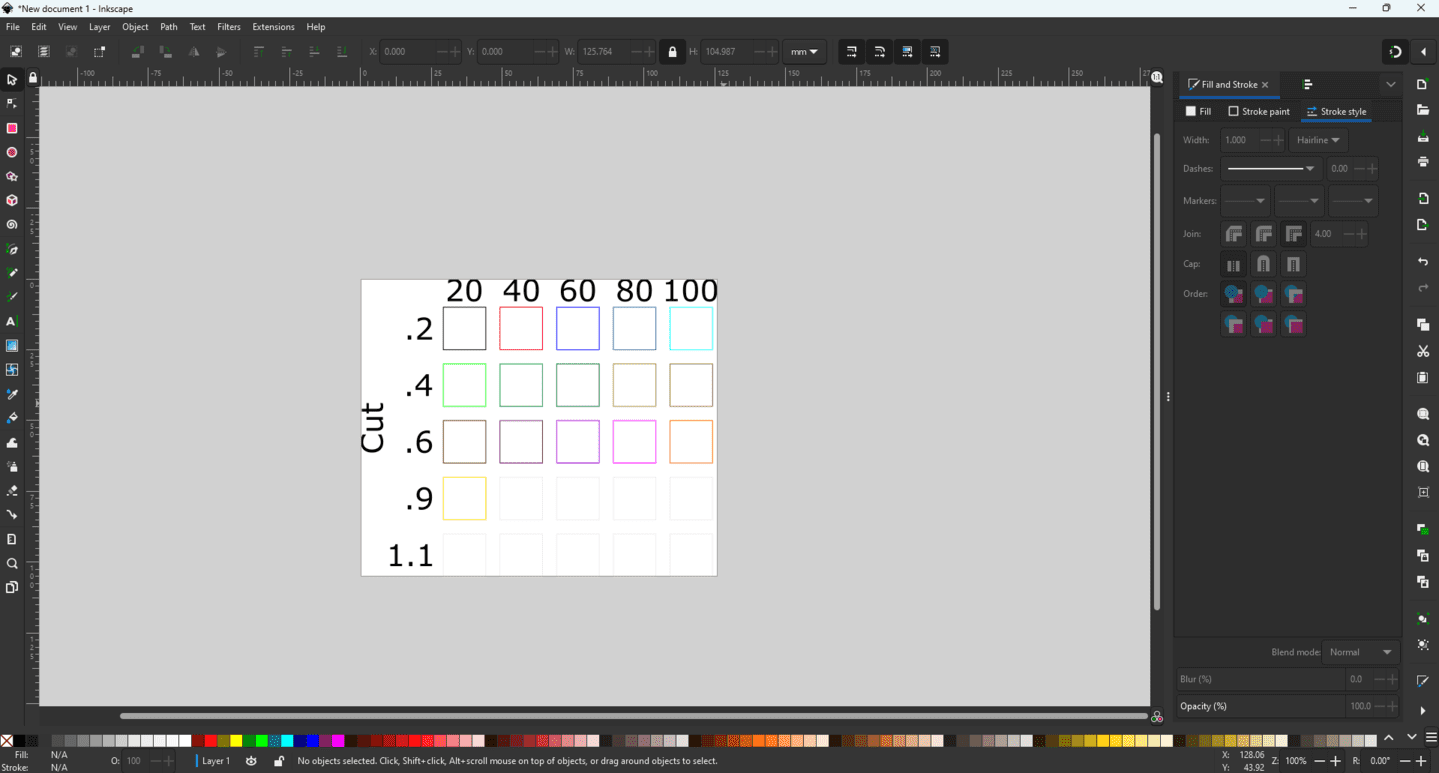
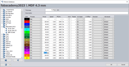
For mdf board with thickness 4.3mm we used different colors with different power and speed as shown below:
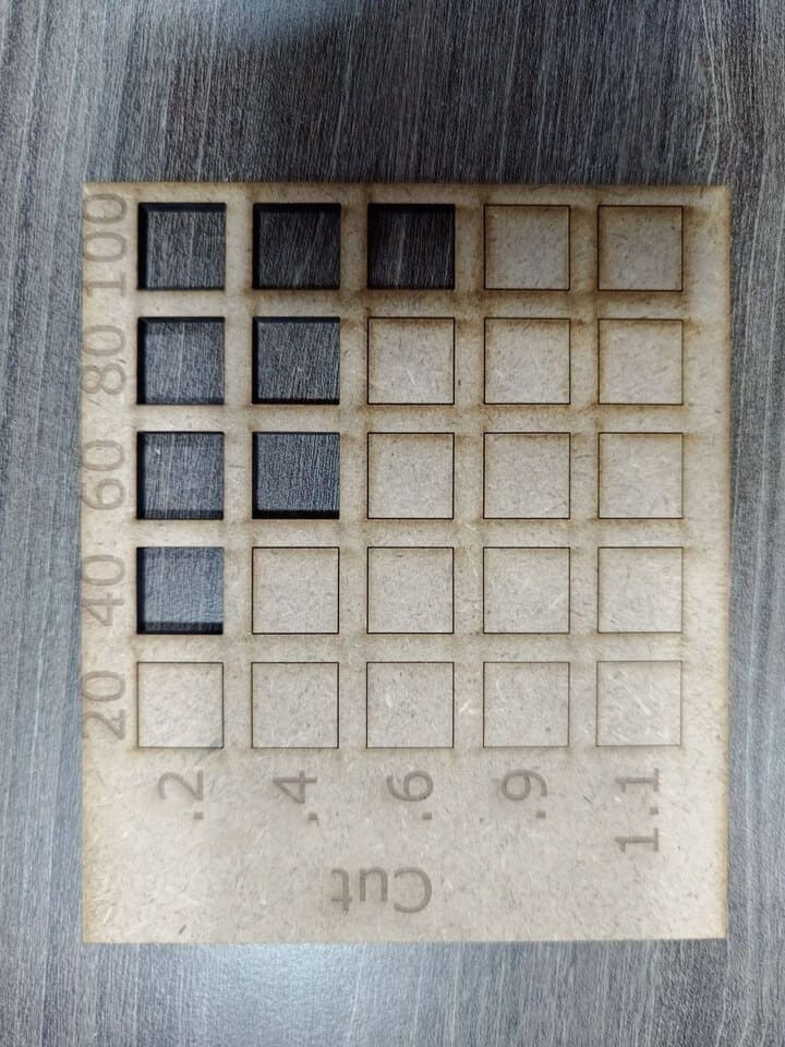
After cutting, we measured the rectangles width and height, and we found that the best value for cutting mdf 4.3mm thickness are P:100, V:60 since it's more accurate compared with other rectangles and operated with full machine capacity and maximum valid speed:
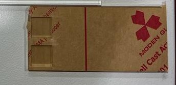
We did the same process for acrylic 3mm thickness, we noticed that at 0.9 speed when power 40 the cut was all the way through, but at the same speed and power 60, the cut was not through, and that was making no sense:
We checked the values of the power and by mistake the power instead of being a 40 it was 100, so we repeated the cut at power:40 and power:60 both with the same speed:0.9 and the cut was not through:
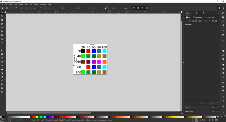
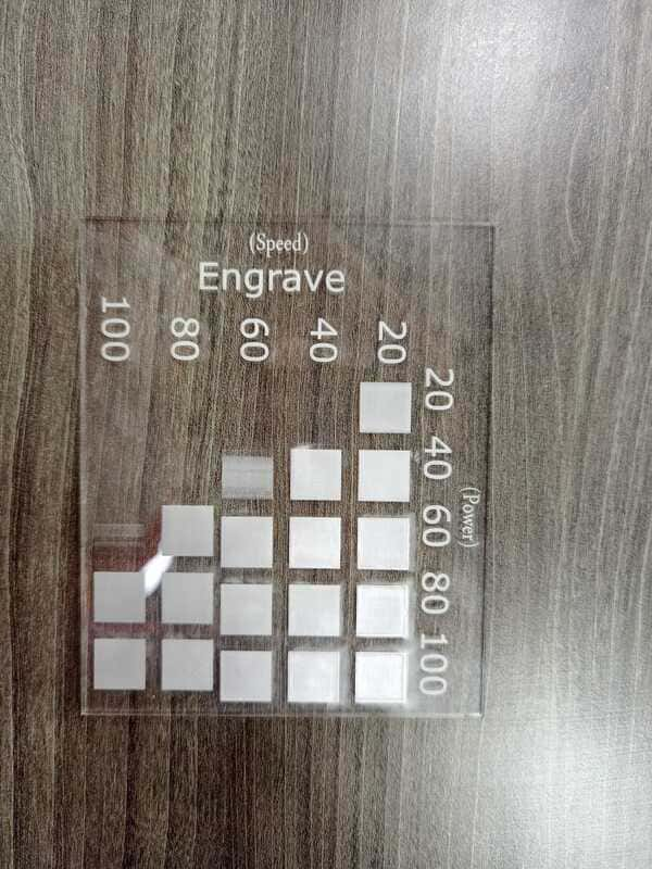
To start the engrave tests, we used the same shape but with fill colors, since to engrave parts we should use colors as fill not stroke:
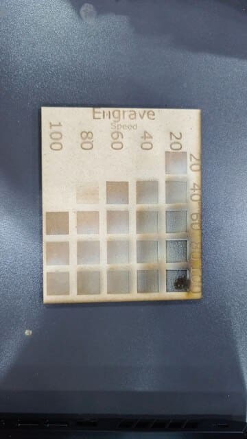
For the first engrave test, we used mdf with 4.3mm thickness, and after the machine fished engraving, we compromised between power,speed and the visual factor and we conclude that the best engrave values were with P:100,V:80 :
The second engrave test is with acrylic 3mm, using the same power amd speeds as mdf, the best values were P:100,V:100 :
To calculate the kerf for mdf 4.3mm, we made a big rectangle with 100mm width, and divided it into ten small rectangles, and the result was:
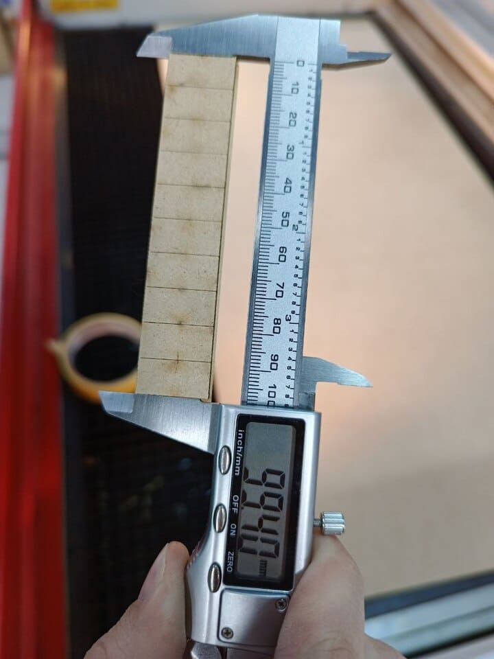
The kerf could be found by this equation:
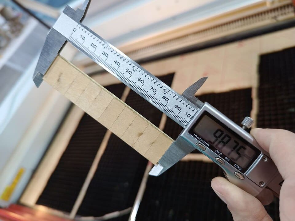
To calculate the kerf of acrylic 3mm, following the same procedure:
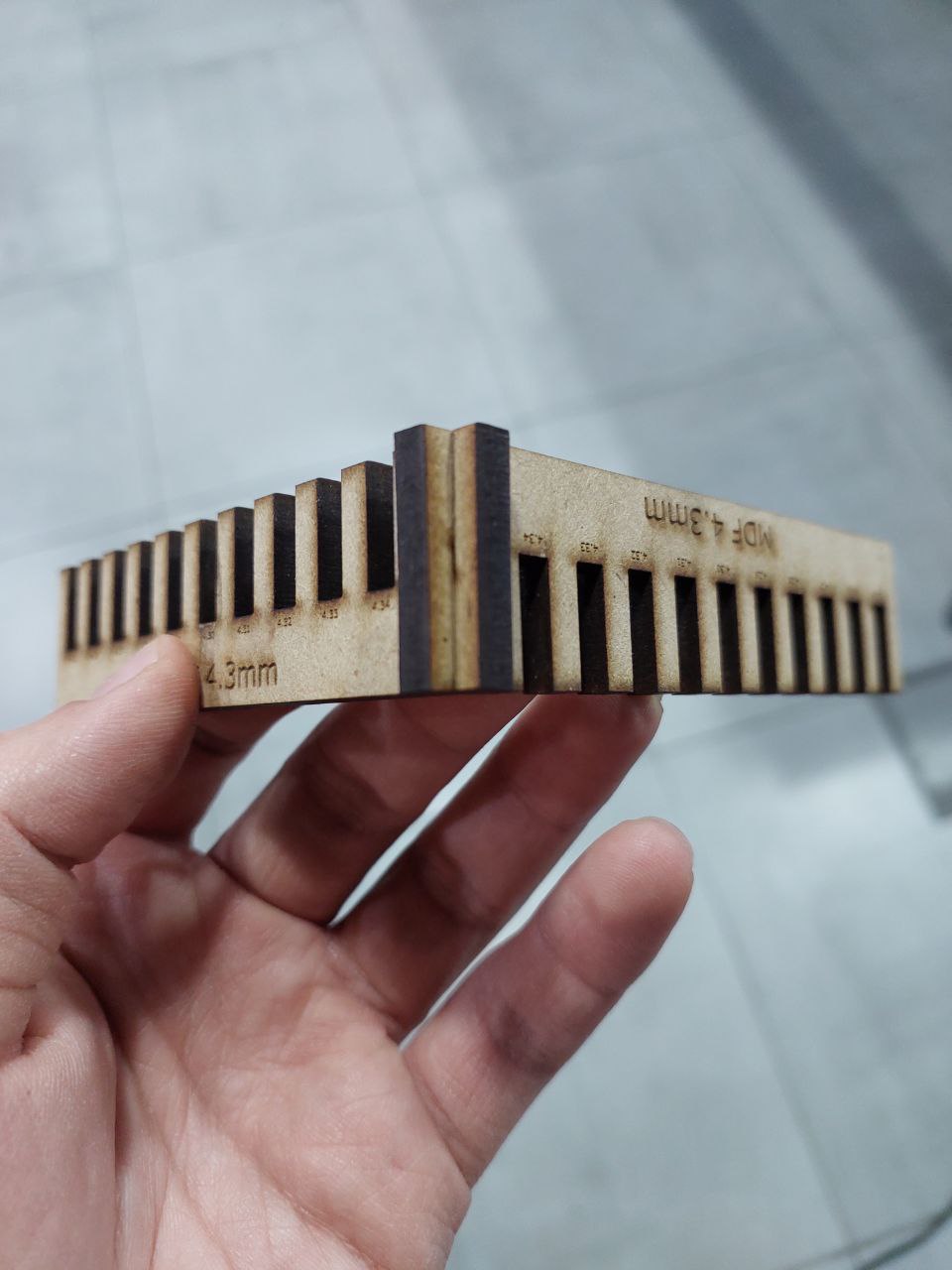
Final test is the joint test for mdf 4.3mm and acrylic 3mm, and starting with mdf the best joint thickness was 4.35 mm :
For acrylic, first, we tried to cut with a range of 2.95-3.05 mm, which did not work. The joints were loose since the kerf value for MDF was smaller than acrylic, so we tried the second test with a range of 2.8-2.9 mm, and it worked actually, but unfortunately, when we removed the acrylic sticker, the joint was loose a bit, so we did the final test with range 2.7-2.8, and finally, the best joint thickness value was 2.74mm as shown below (from right to left):
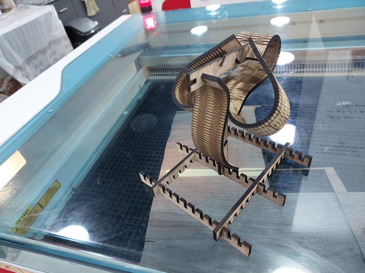
Parametric Design (rectangle kit magic)
I used fusion 360 as a CAD software to make my parametric design my design is explain the magic of the rectangle and how we can use it in different way to construct deferent shapes that can be useful and fun in same way
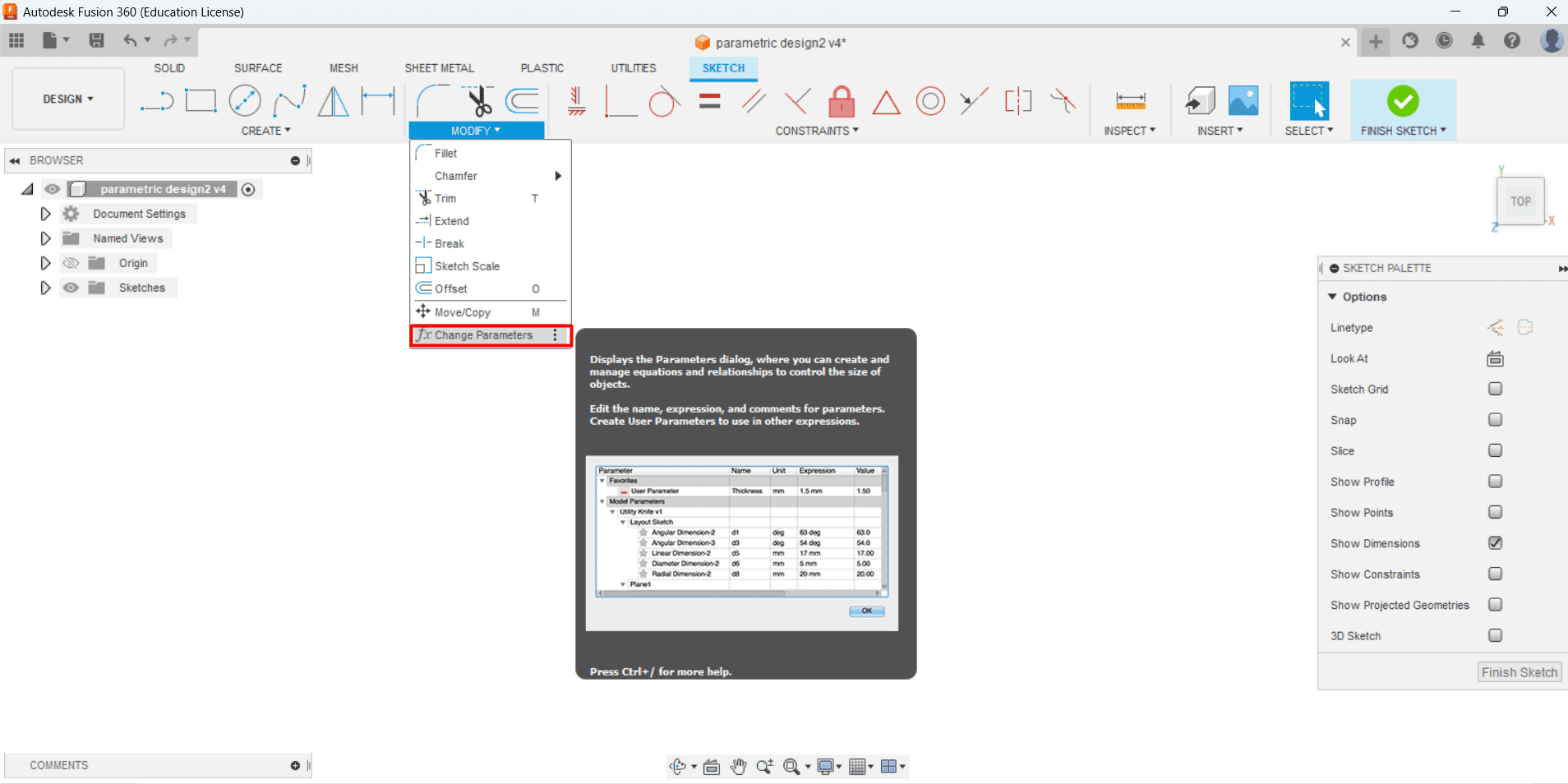
So, to start to draw parametric design in fusion you should identify your value using the change parameter click
Then here you add your parameter
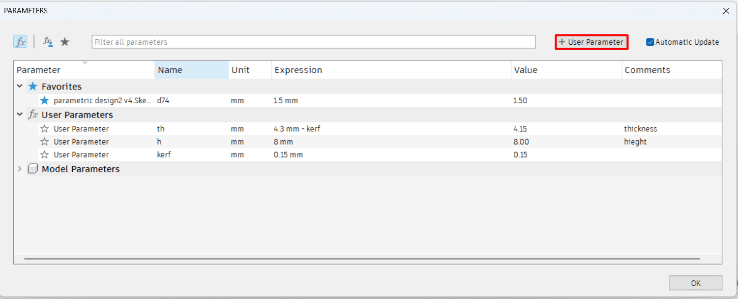
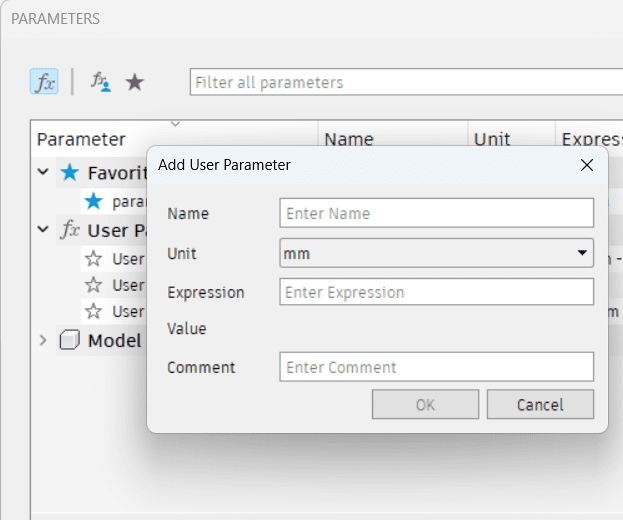
By clicking on user parameter and add your parameter , for me I have three parameter the thickness of the wood and the height of the joint and kerf value ,As this:
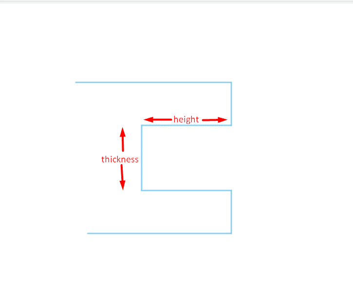
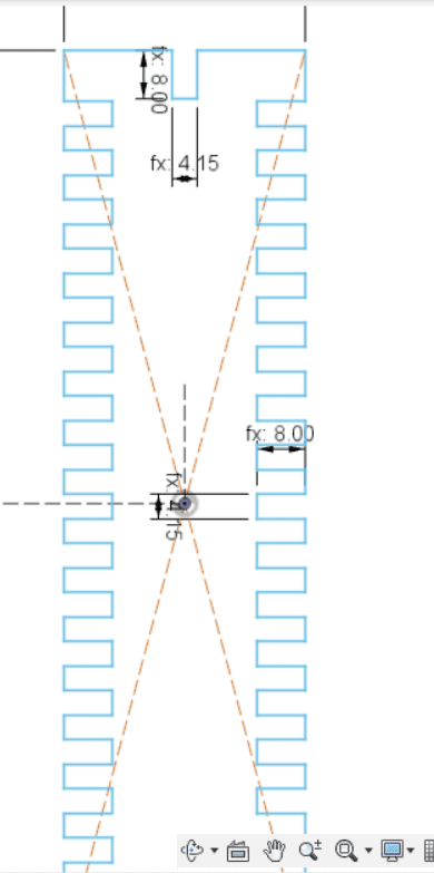
so for me the kerf for the mdf (4.3 mm) is 0.15 mm so that mean the laser cut more from the cut path by 0.15 mm ,so I offset the cut path down by reducing the thickness parameter by 0.15 mm ,so joints will be fit without any loose

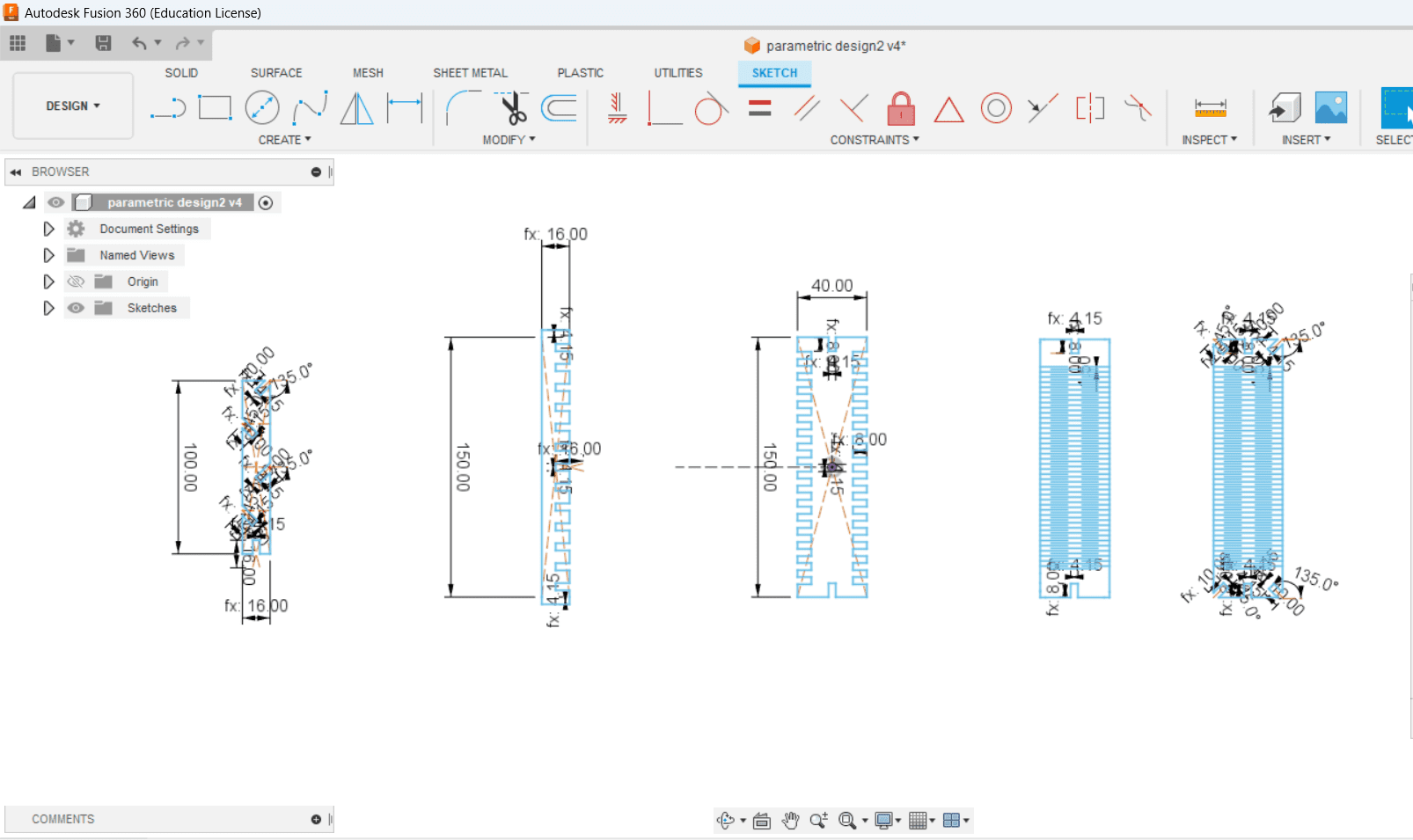
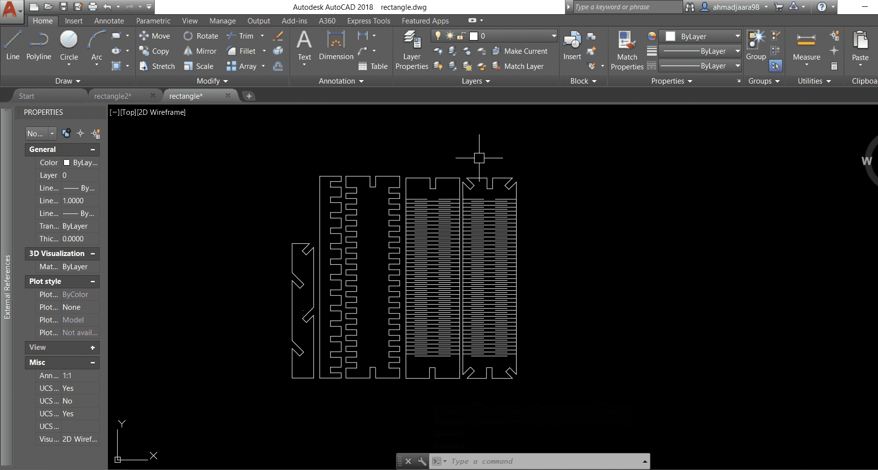
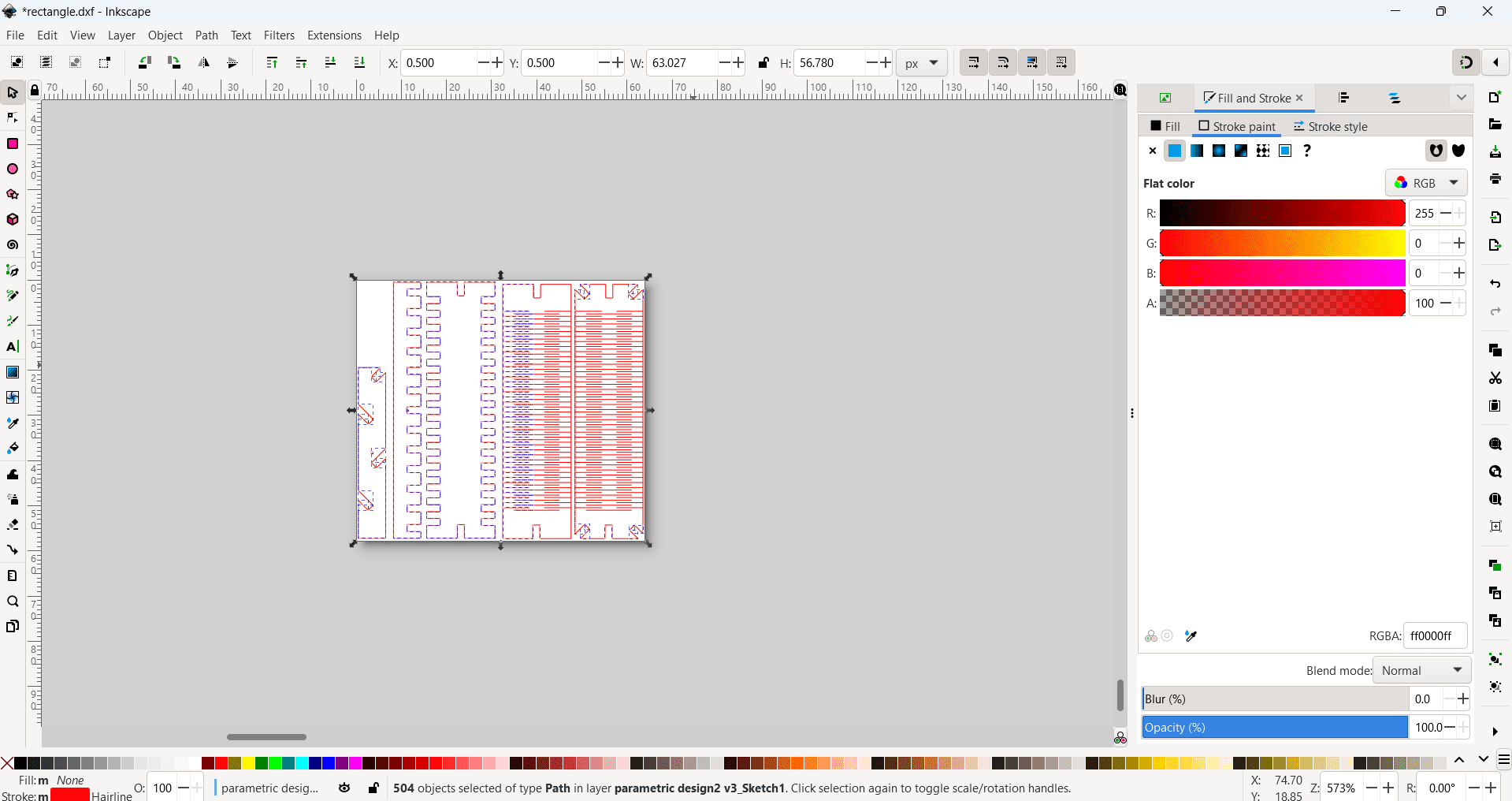
Then I export the design as dwg to remove construction line using autocade since it's easier to remove it from autocade, then I save it as DXF to color it using Inkscape for laser machine
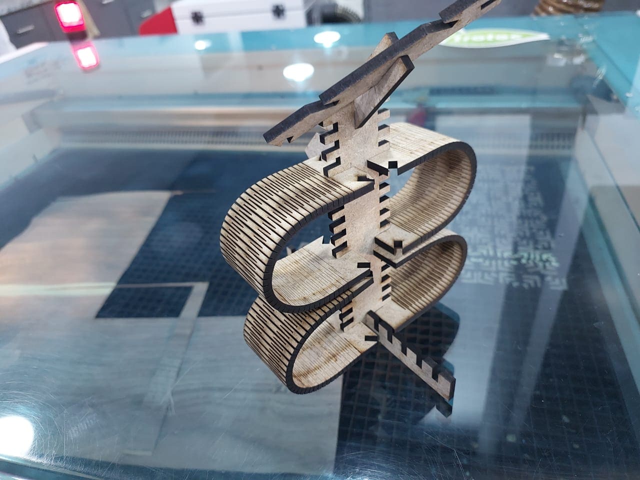
An important note when you design a living hing you should take care for the distance between hinge slot so it still have its flexibility and strength ,I try different distance until I found that 1.5 mm is the best distance between slots for my design,then after researching I find out that there is a research that give you a useful equation that will help you in your design
living hinge rule
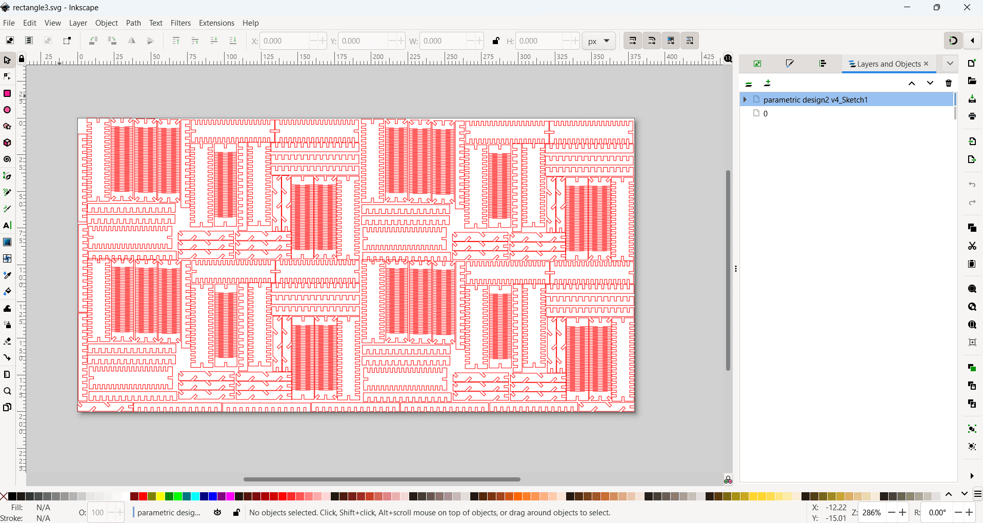
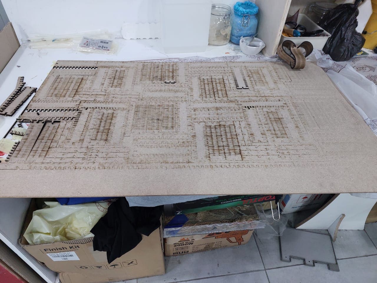
here I used my organizing skills to fit as much as I can of the rectangle kit inside a board sized with (100*60 cm) , I feel its cool
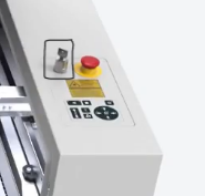
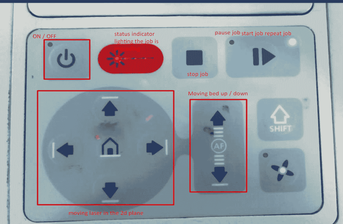
So to run the laser cutter ,I turn key switch ,then I put the mdf board on the laser bed,after that I need to using the focusing tool which focus the laser distance depending on the material thickness, to move the laser location I use the control panel ,that give you the ability to move the laser cutter in x and y plane , move bed up and down and other useful features
Focus Tool
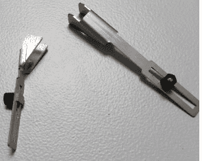
Moving bed until Focus Tool drop down ,by using the control panel movement controller
Control panel features
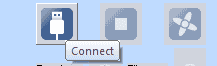
then in job_control window ,I connect the software to the laser cutter by pressing the connect button
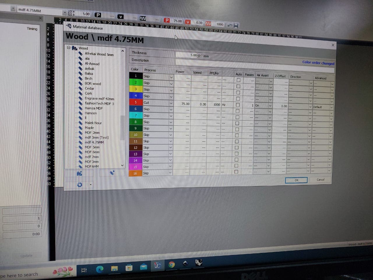
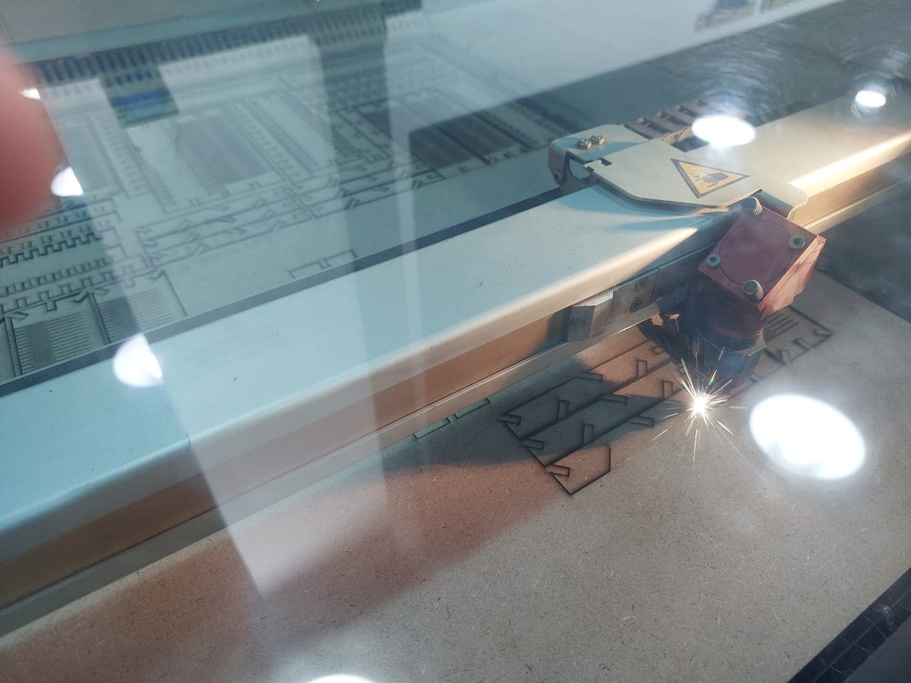
Then I start cutting my design on the laser choosing the setting of cut (power and speed) (75%power,0.3 speed),then press run
Then start the laser magic
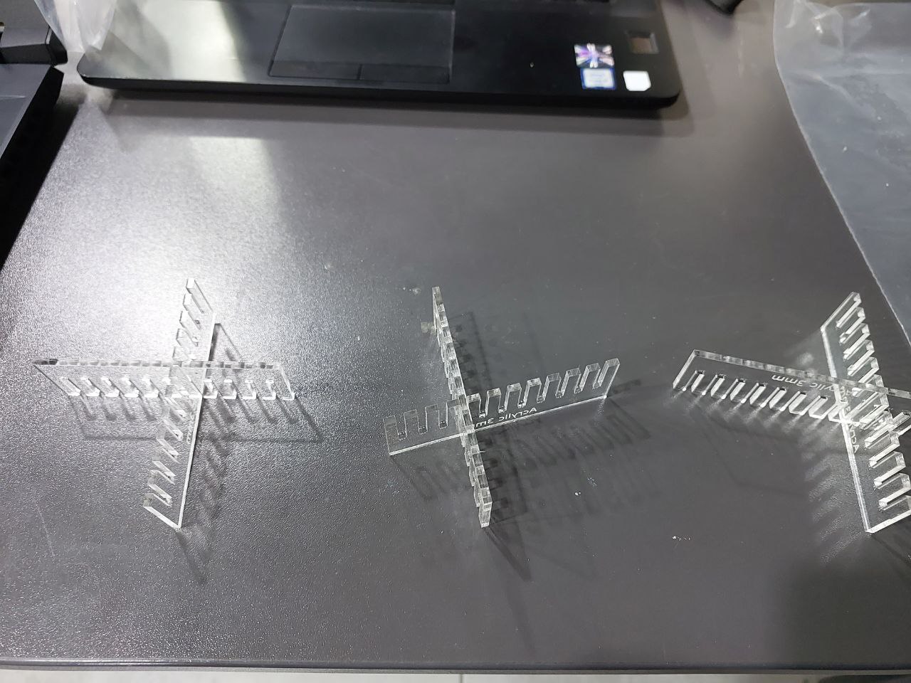
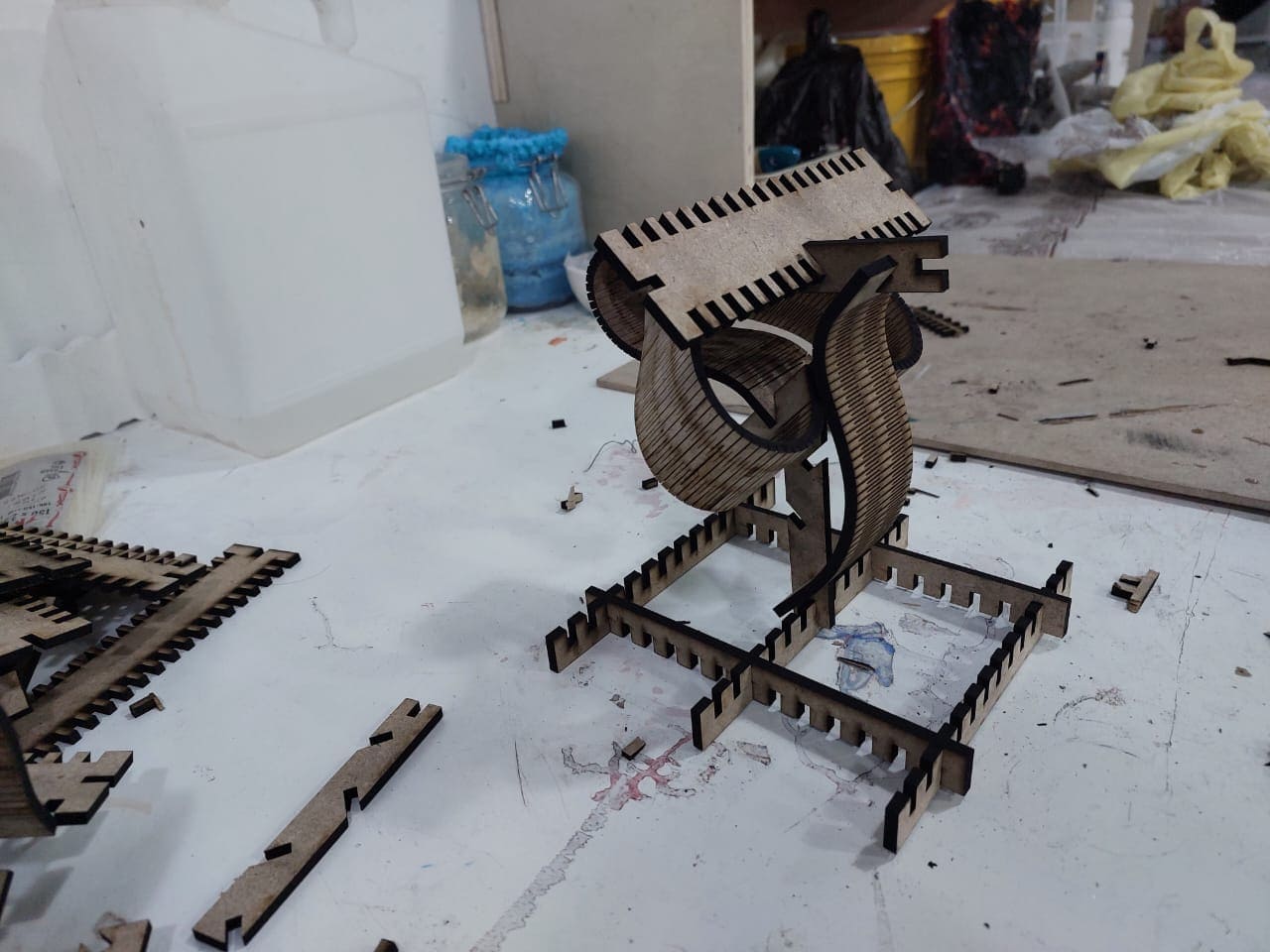
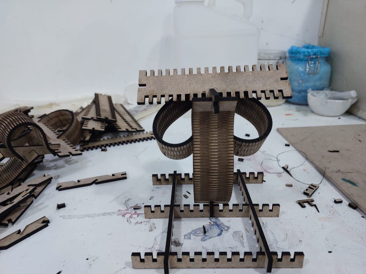
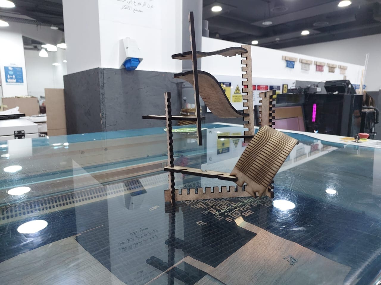
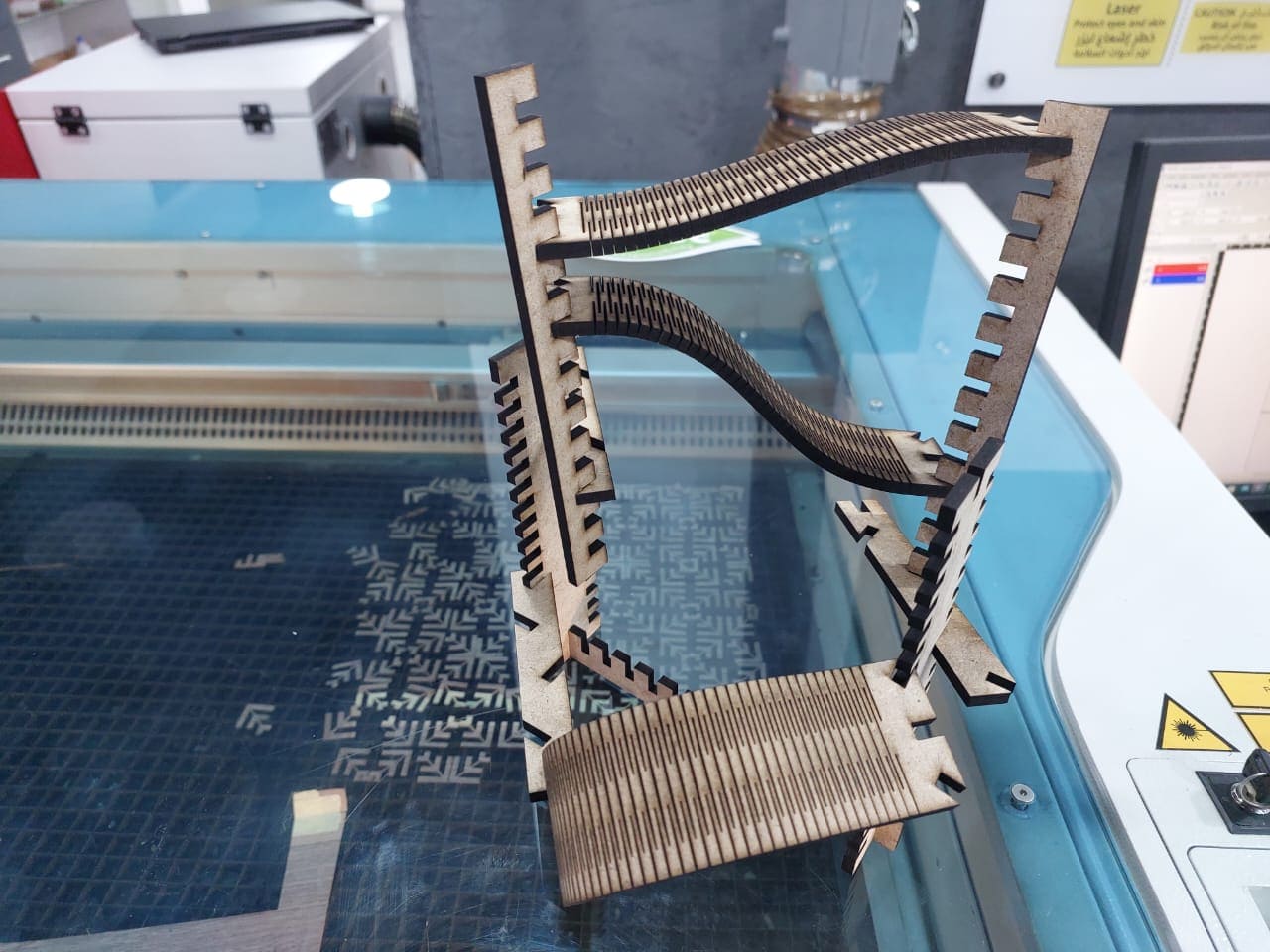
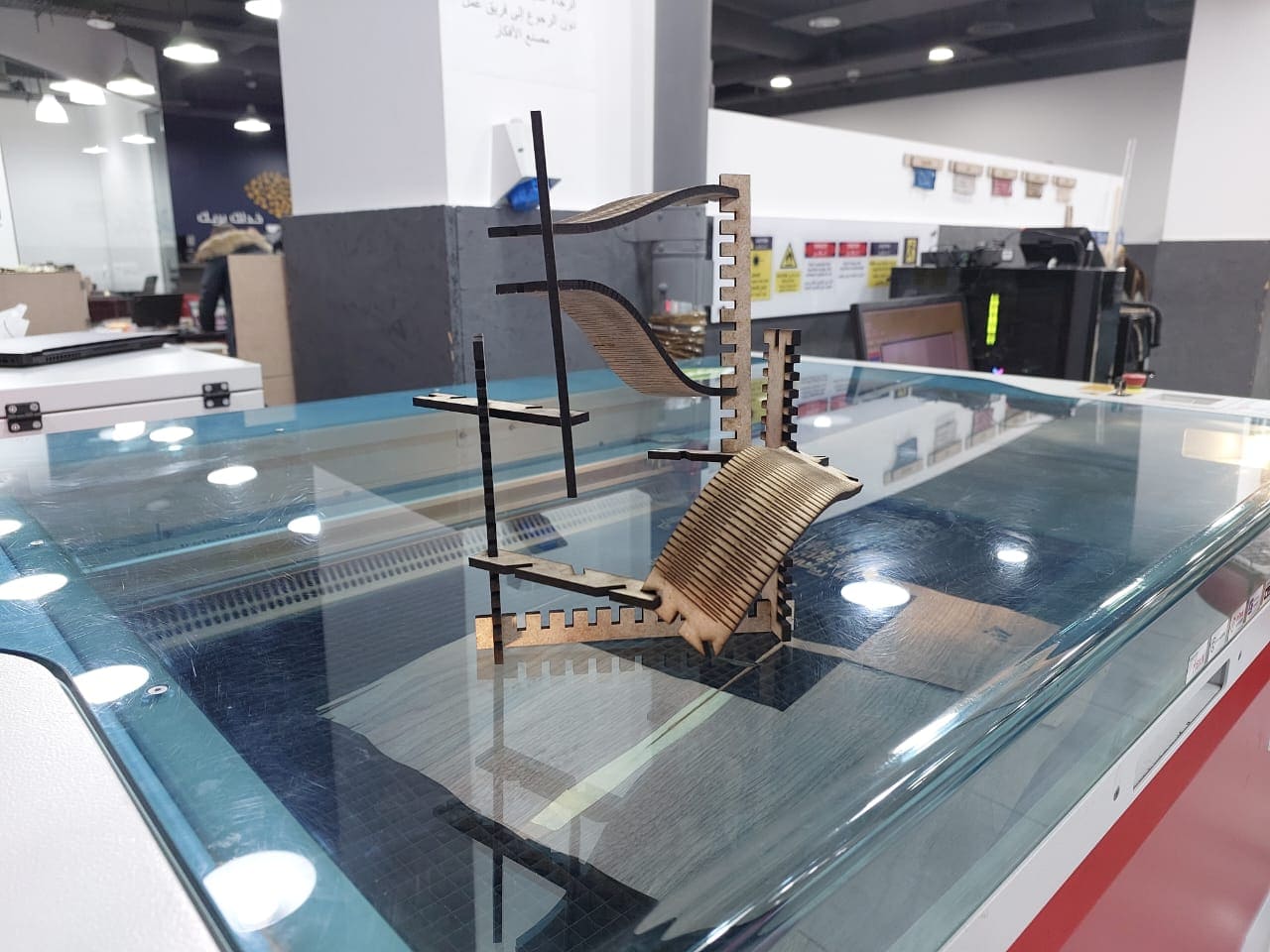
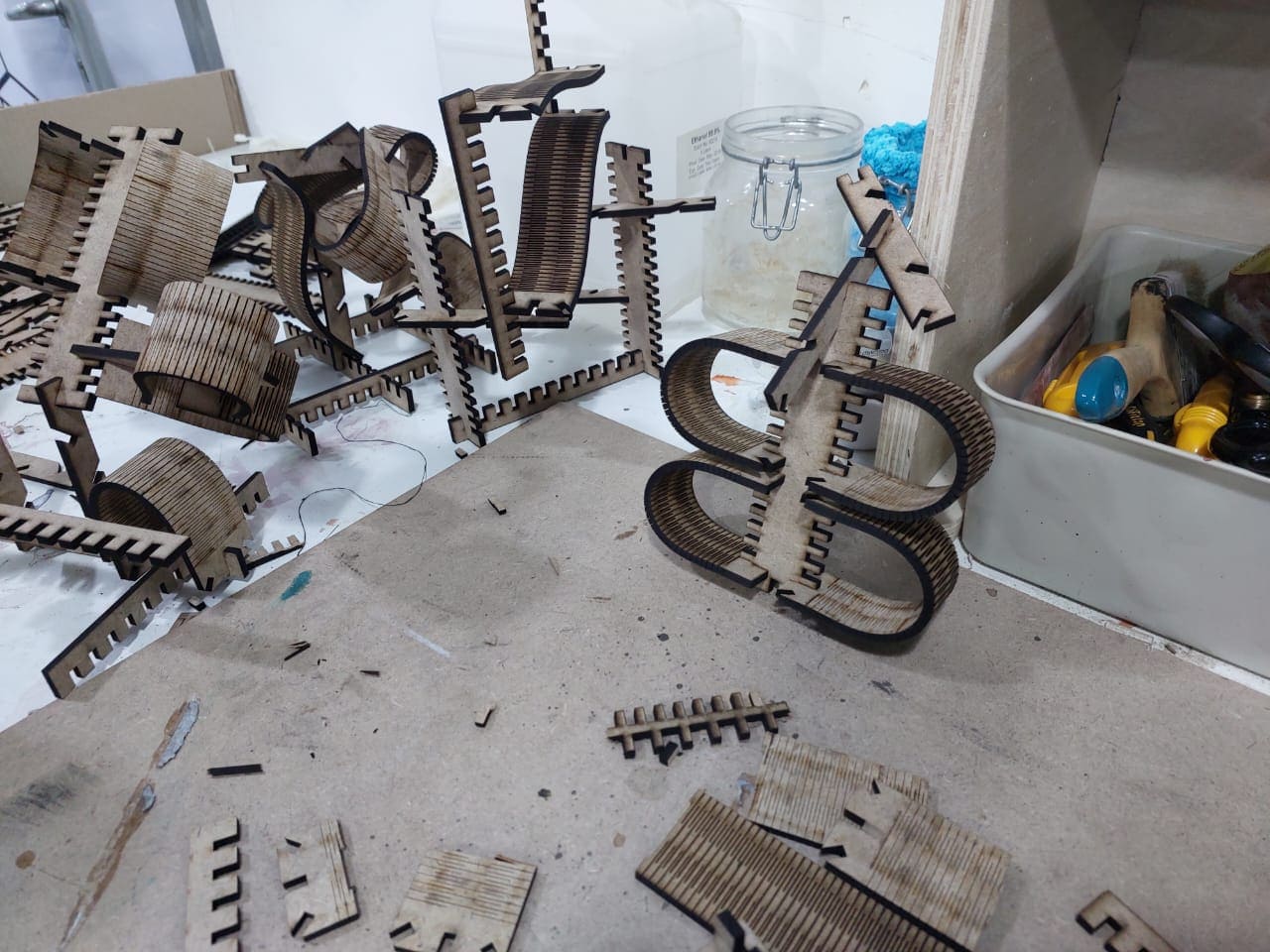
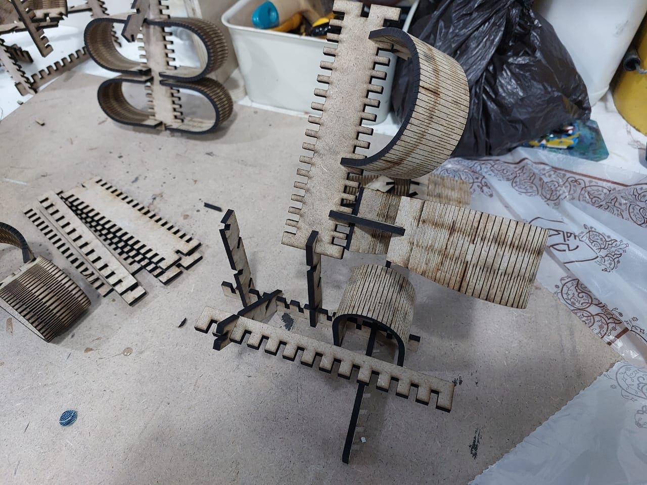
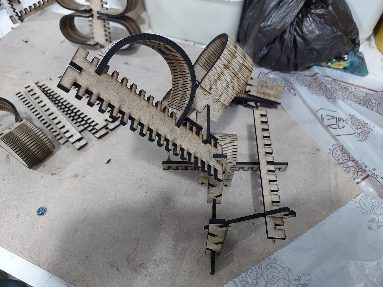
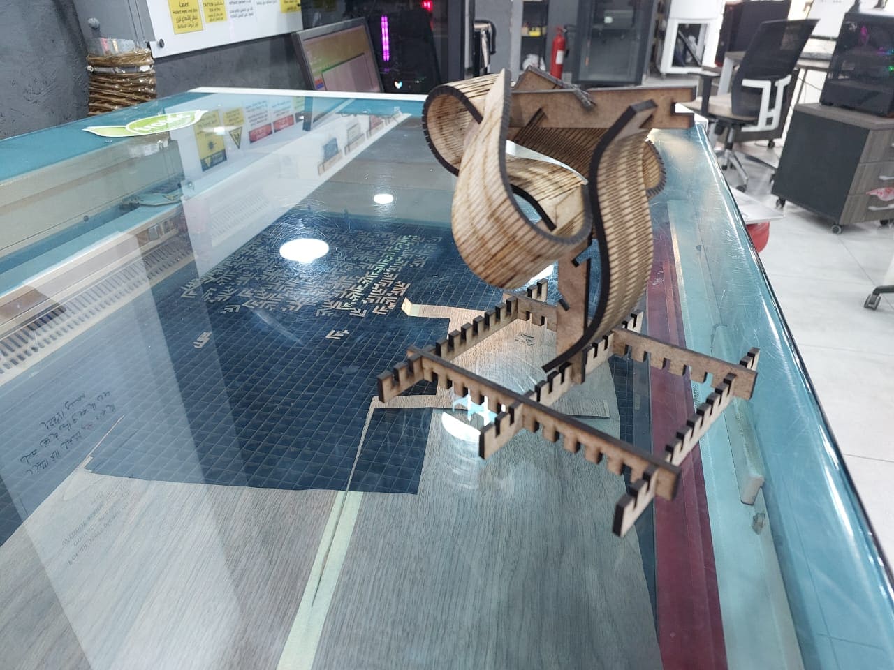
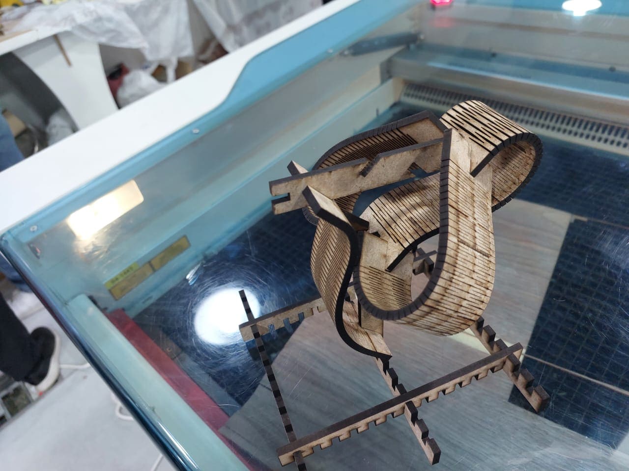
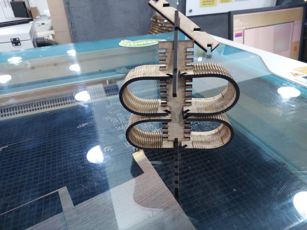
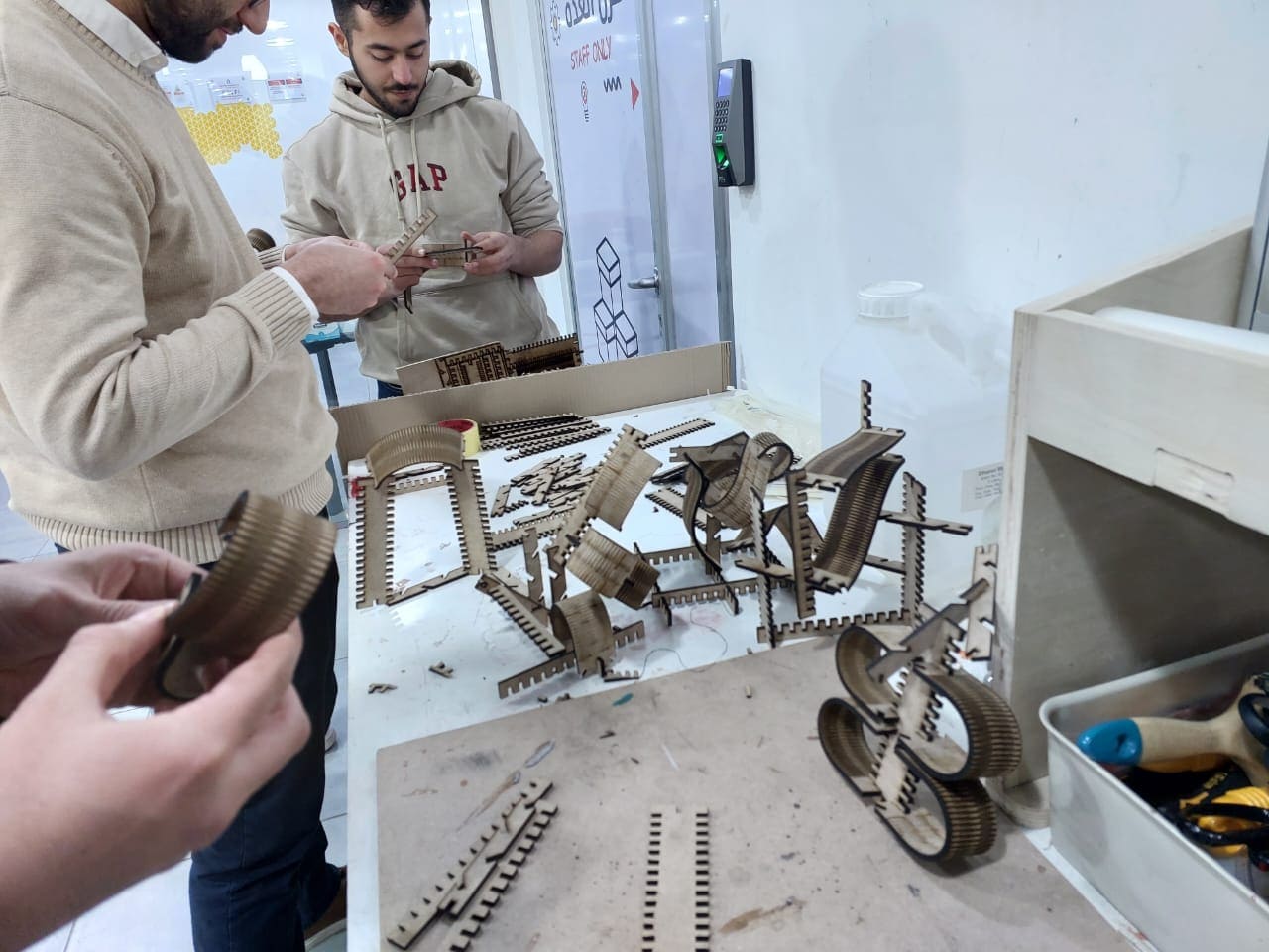
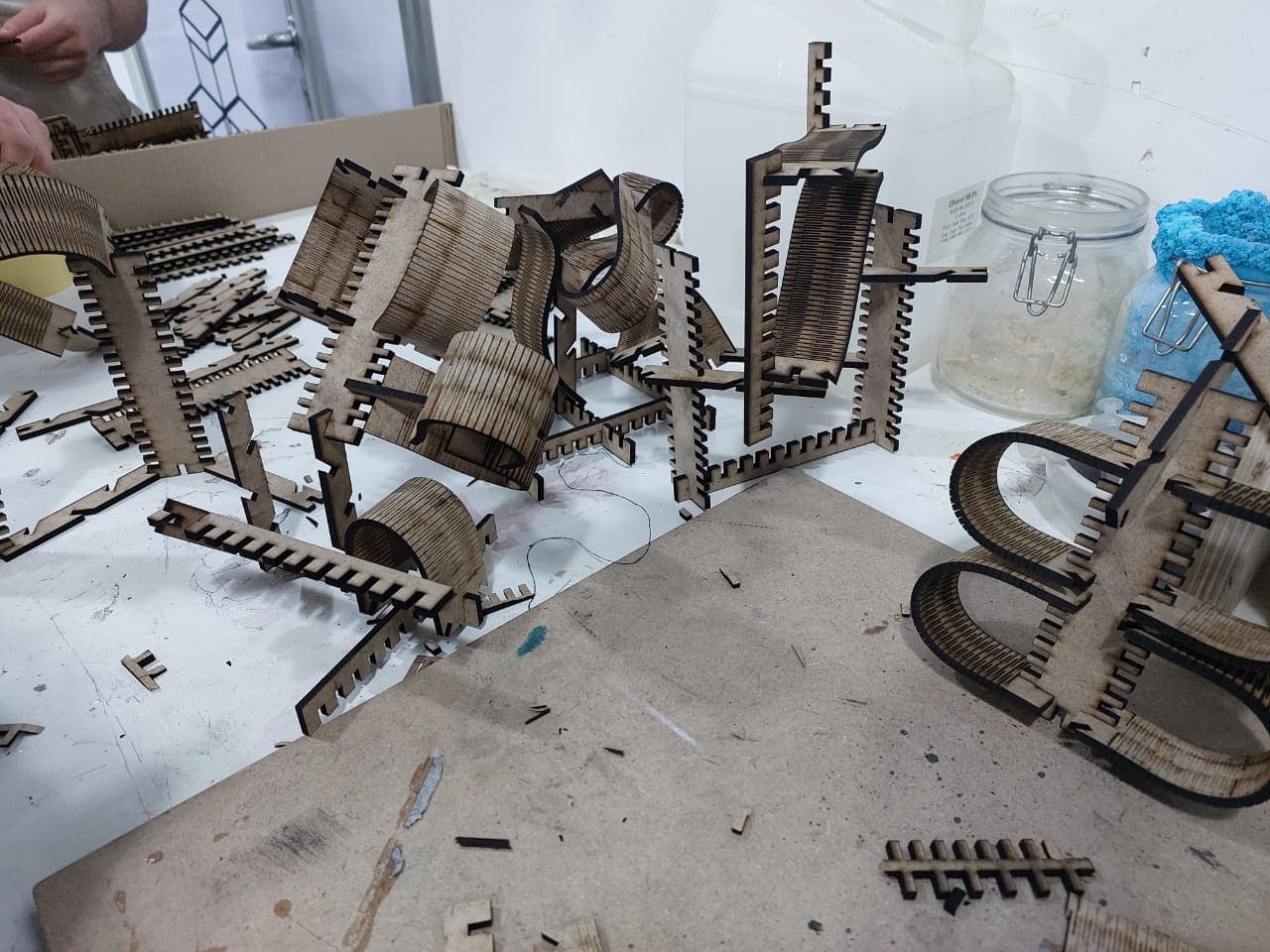
And I create these shapes from the rectangle kit with my lab colleagues
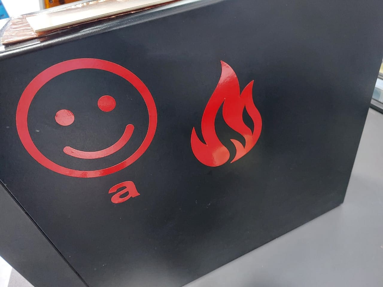
For the vinal cutter I make a fire sticker, for the software I use cutstudio software to cut my sticker, so I take the picture form the browser and put it inside the software and take the contour outline from it , below are the process steps
our machine roland vinal cutter
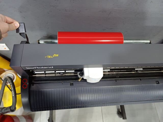
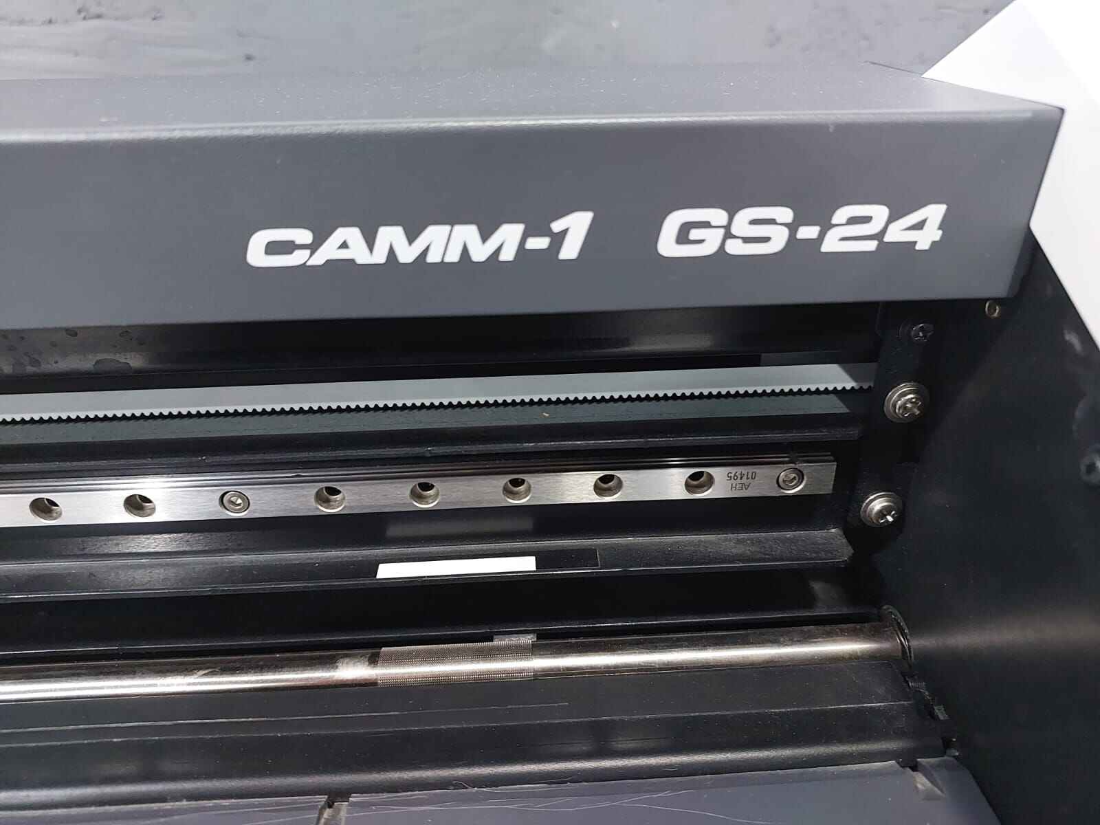
its model is CAMM-1 GS-24 ,you can find more about its specification from here
before starting the vinal cut ,you need to add the material ,so i will use a vinal roll,firstly you need to release the handel to slide the vinal roll through the machine
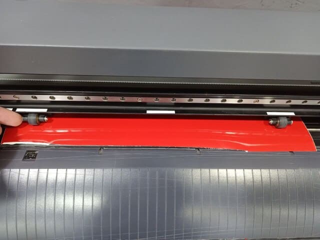
you should that the pushing roll are locate correctly at there place (correct place marked with white color)
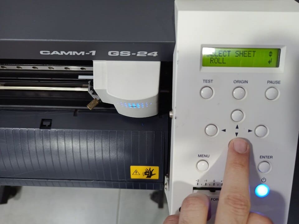
then you should add the shape state of material (roll,piece or edge) then click enter , it will automatically measure the roll width ,and now your vinal cutter is ready
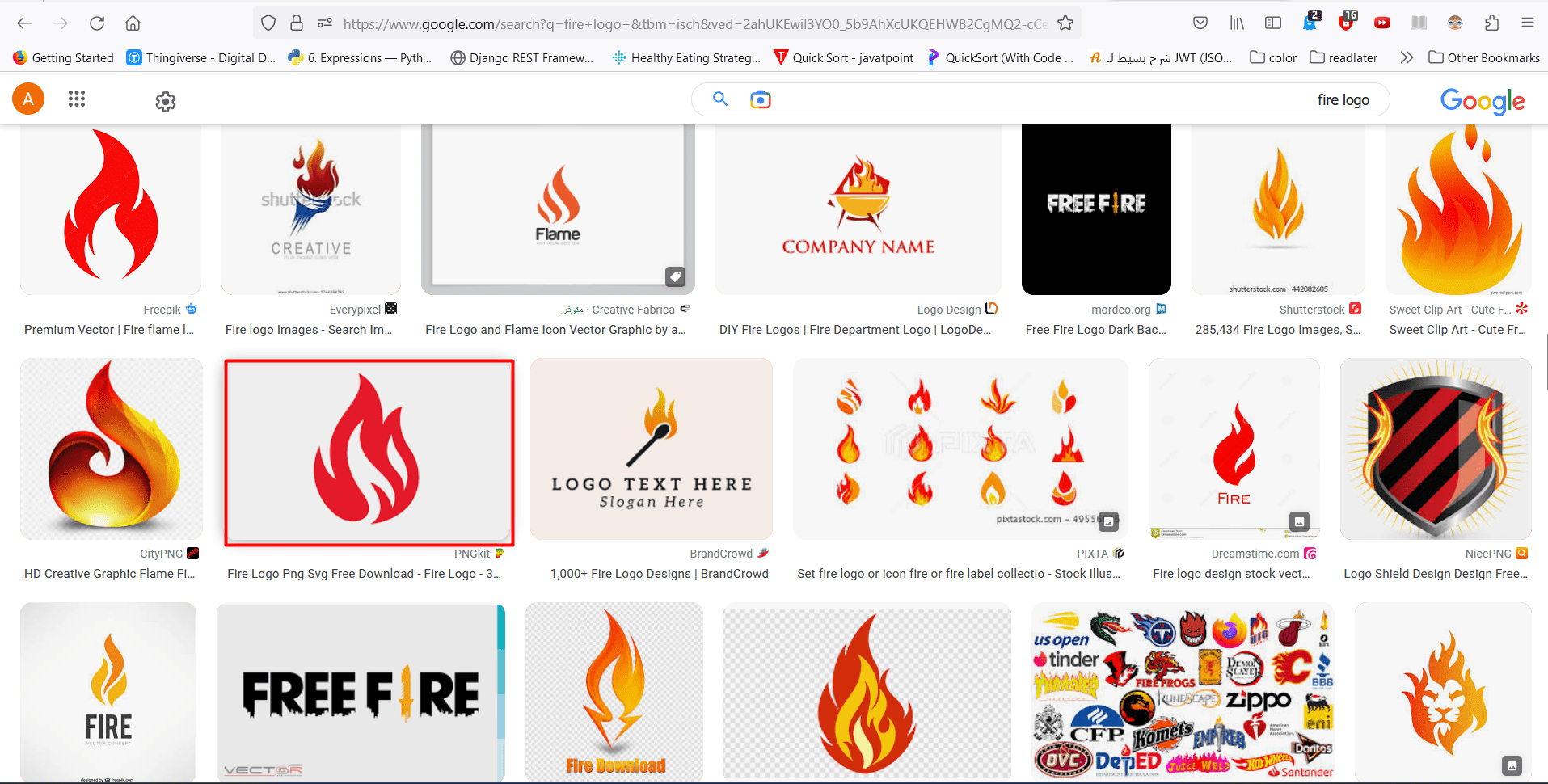
ROLAND cutstudio software take png picture so I search using google to find a fire logo ,I found the image I want then i save it as png after that I put the image inside the software by drag and drop or file then open
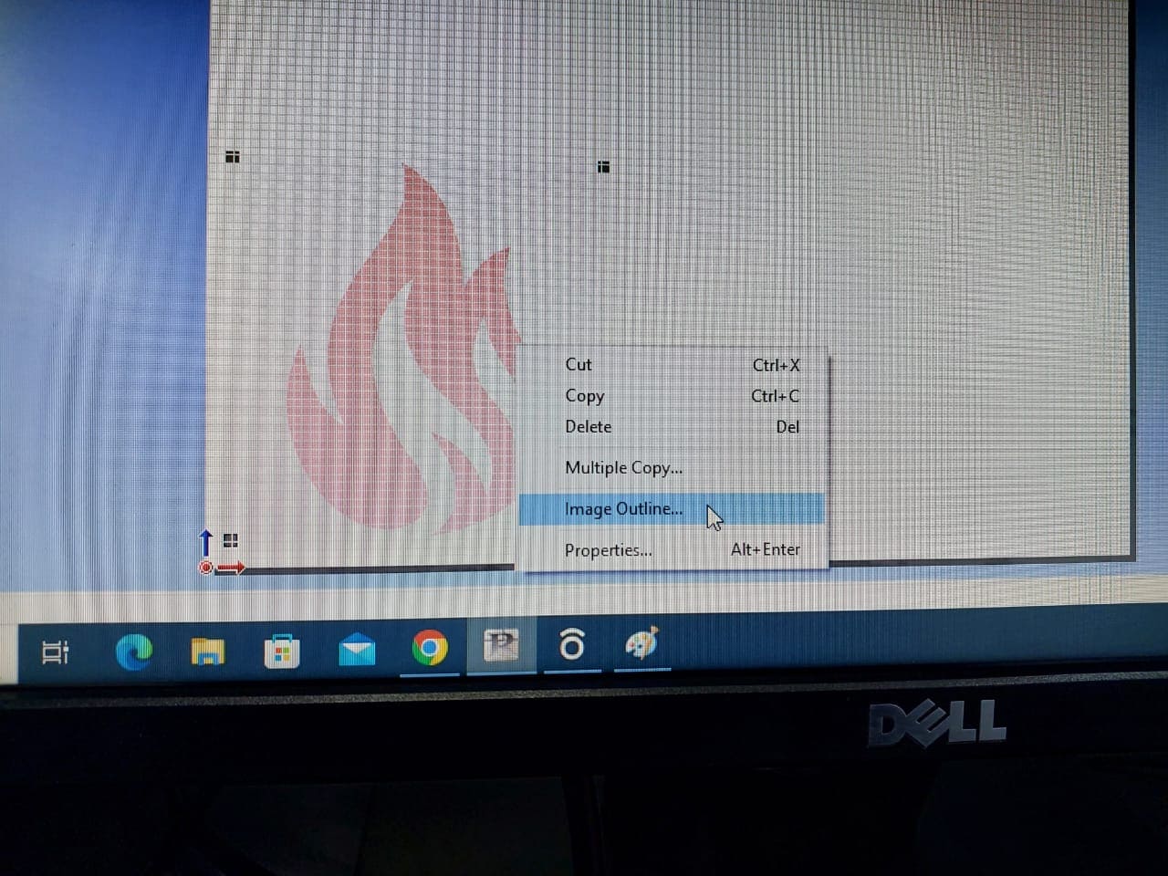
Taking the image outline by click the mouse right click and chose Image outline
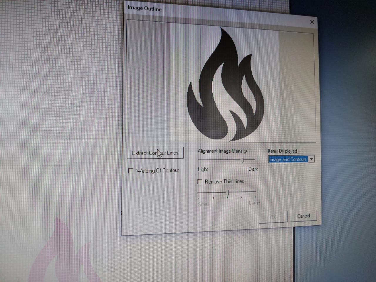
A window will appear click on extract image outline then ok
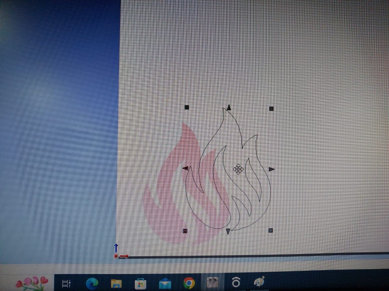
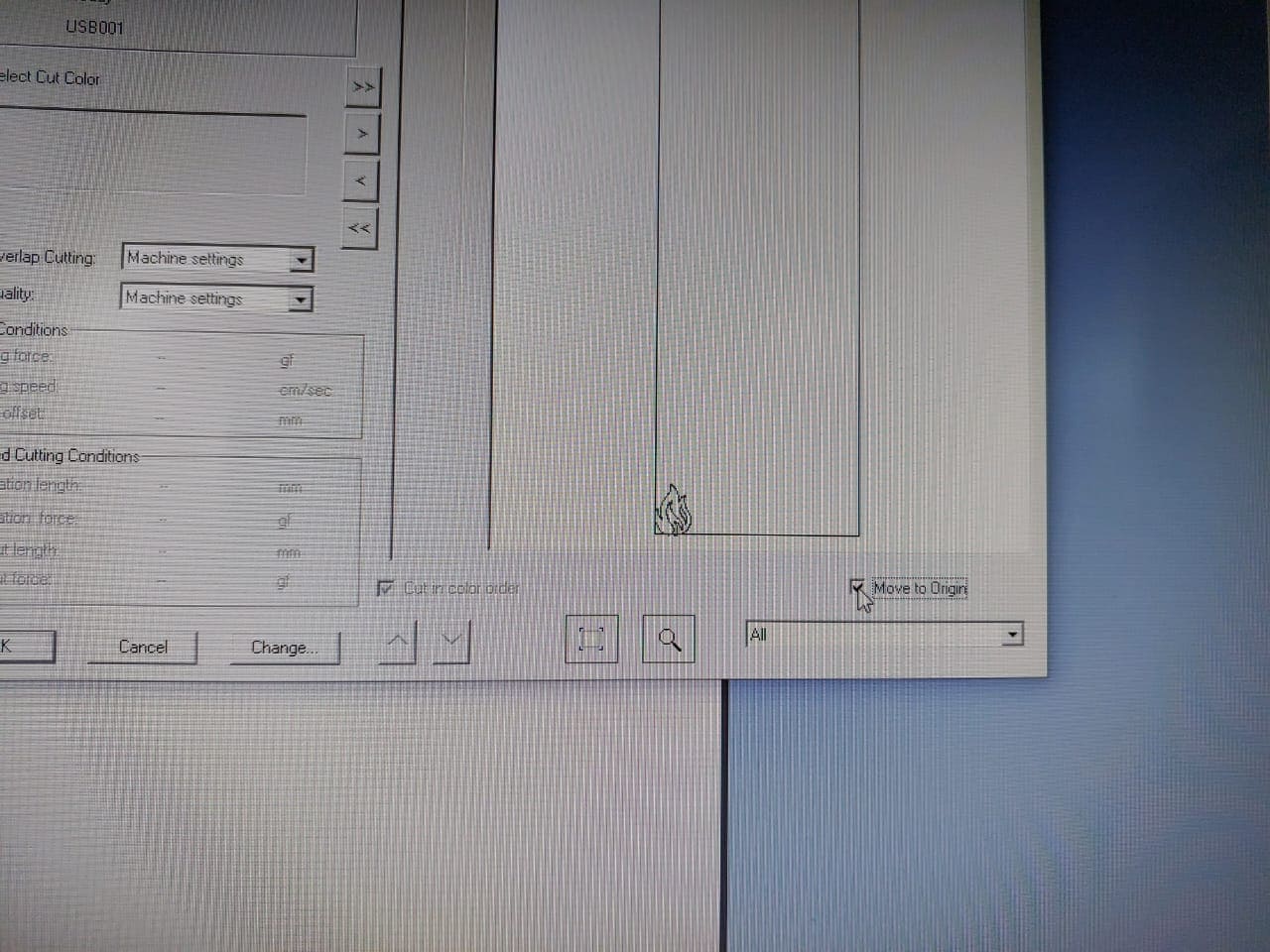
Then delete the origin picture and just press (ctrl+p) to print
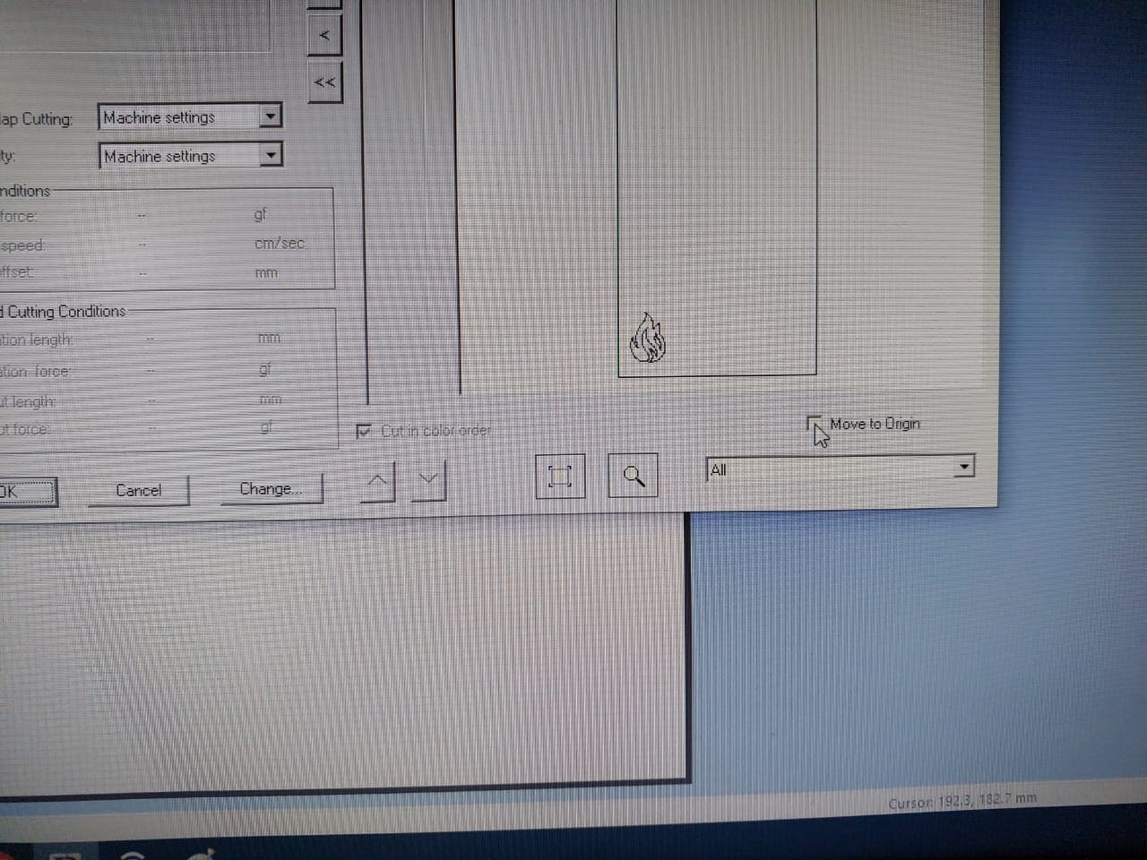
print window will appear click on move to origin to move your design to it then click ok
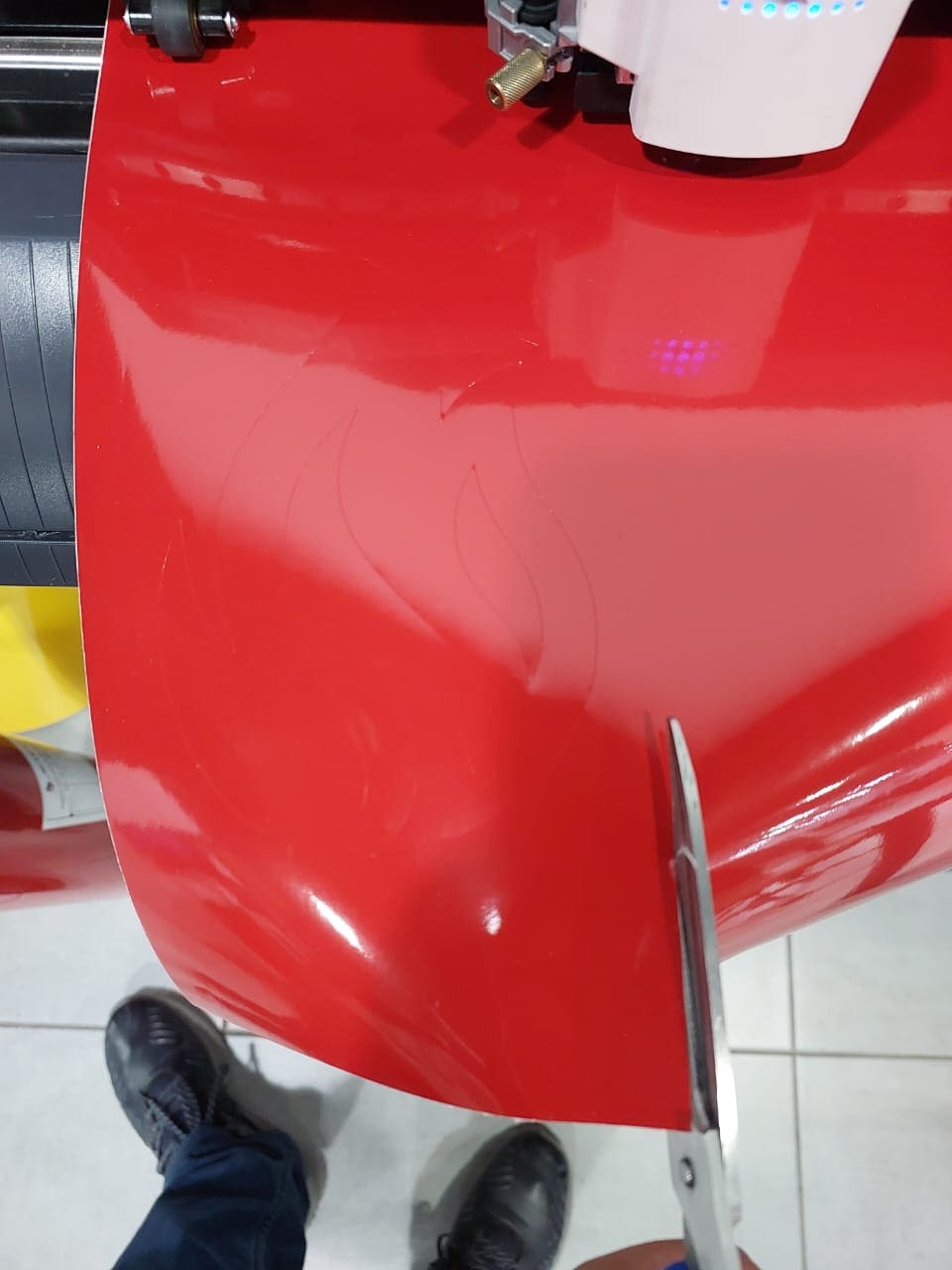
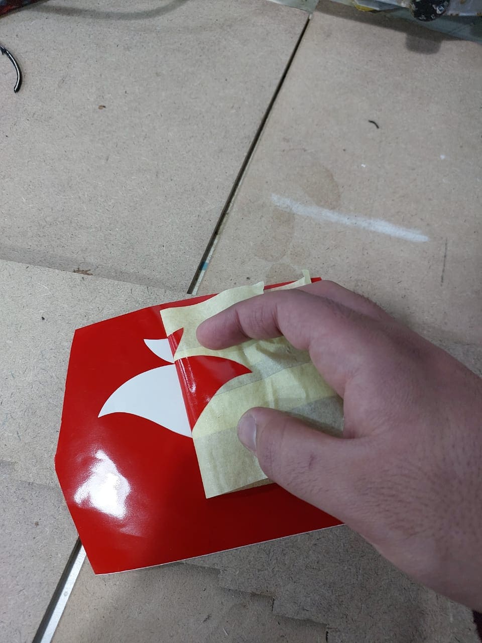
cut the sticker and put the tape on it and check its stick in proper way
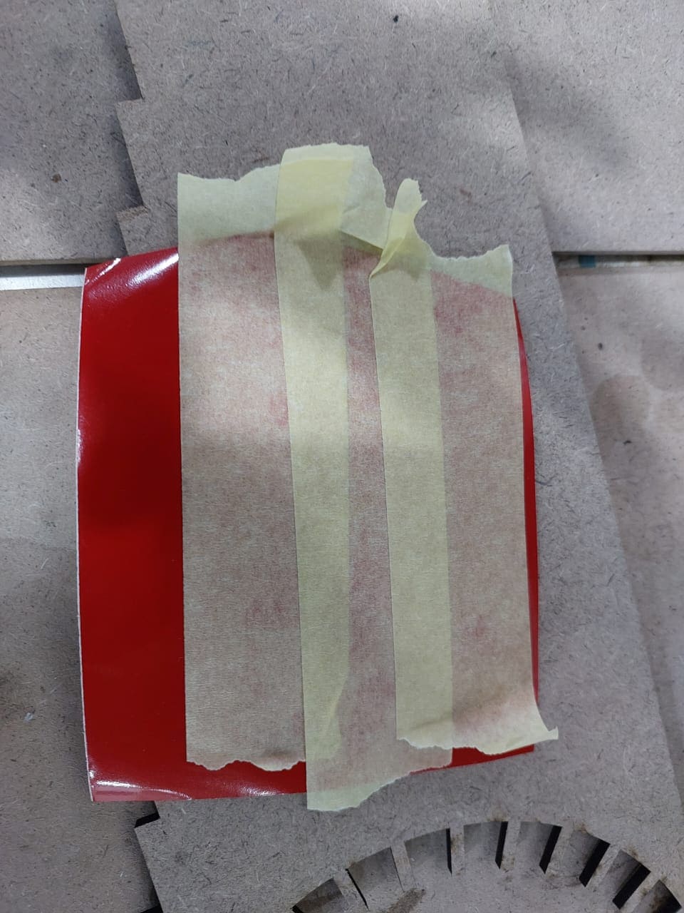
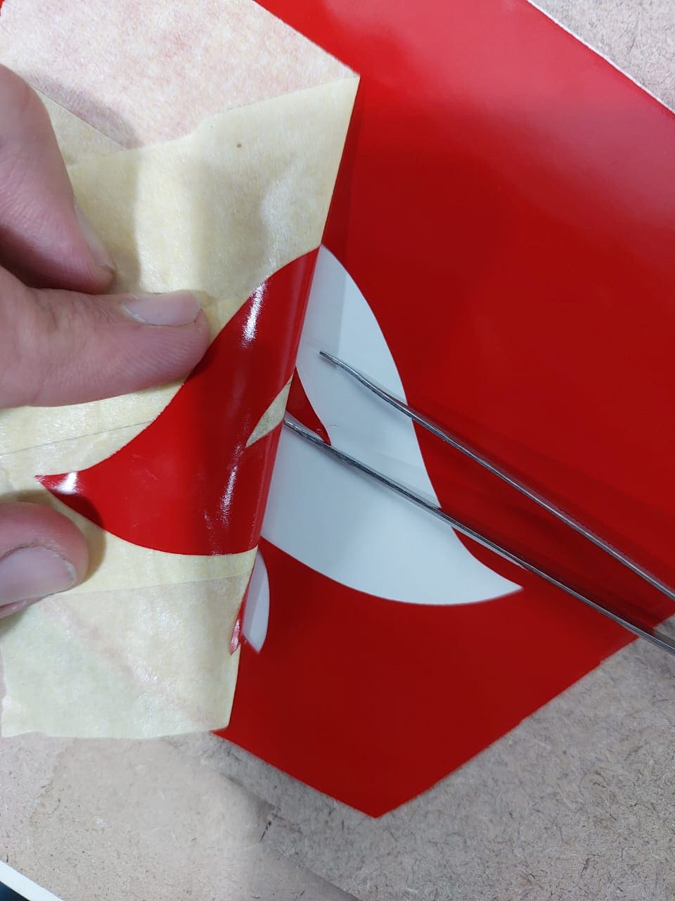
remove the tape carefully and check that sticker is stick on it you can use tweezer to help you in that
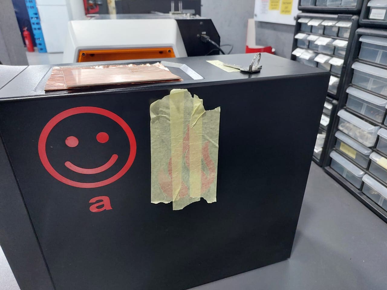
the best moment come when you put the sticker on your device and just see its beauty
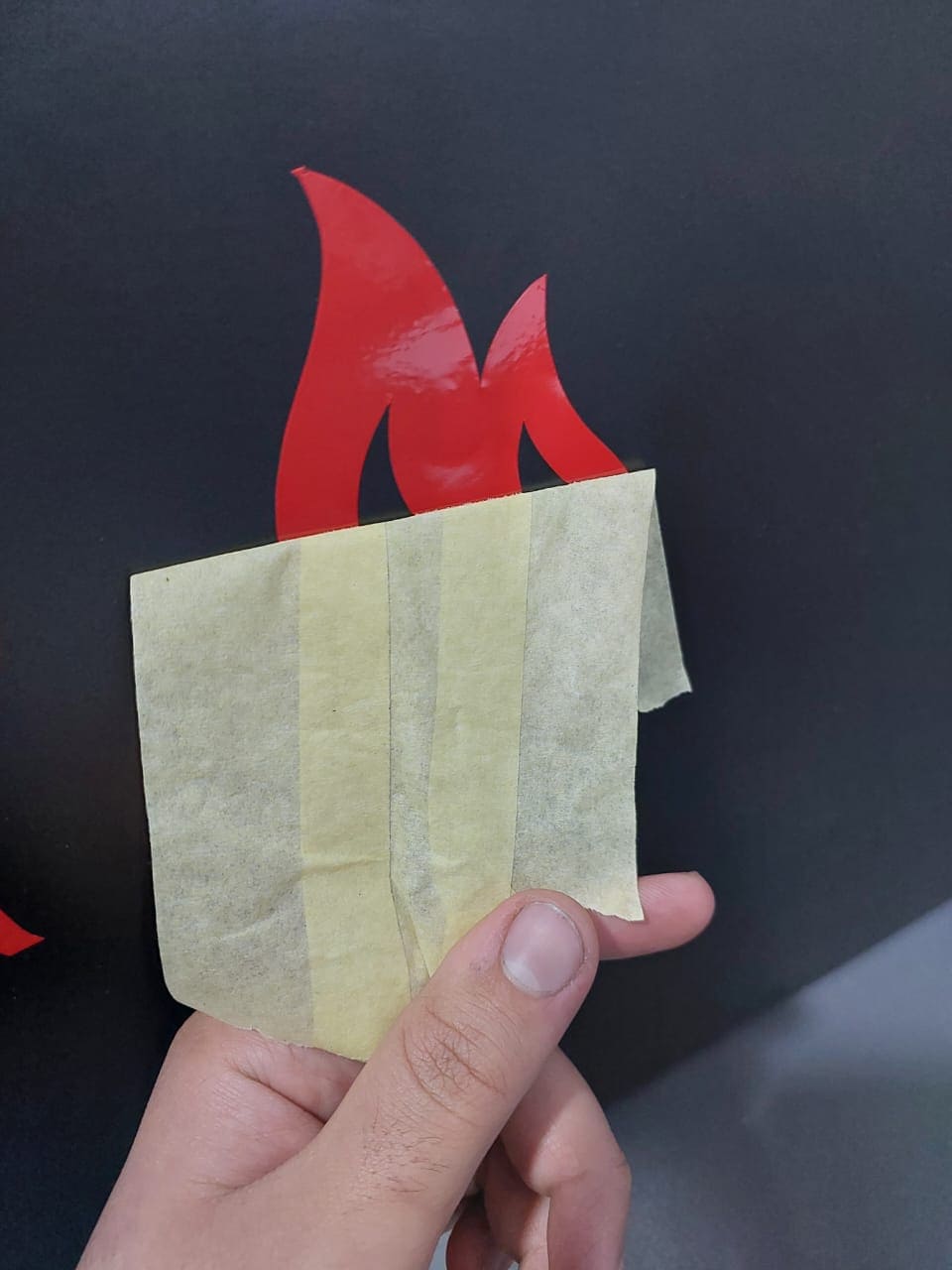

I try to change the process of the sticker as standard process flow by removing firstly the negative part of the sticker ,it goes as follow
.jpg)
.jpg)
.jpg)
.jpg)
.jpg)
.jpg)
.jpg)