Electronics Design
Welcome to week 6 assignment! 
Key Learnings This Week I learned how to design a PCB using Eagle and I learned how to use three important tools for electronics design at the lab!
Classic Electronic Tools in the lab
This week we were introduced us to 3 important tools available at every electronics lab. - The Multimeter - Regulated Power Supply machine - Oscilloscope
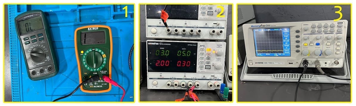
1- The Multimeter:
A multimeter or a multitester, also also called a VOM (volt-ohm-milliammeter), is an electronic measuring instrument that performs several measurement functions in one unit. A typical multimeter can be used to measure voltage, current and resistance and even to check for conductivity. reference
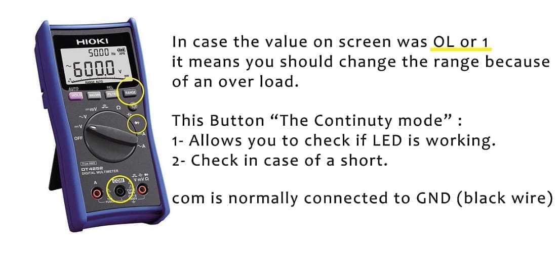
How To use a Multimeter A multimeter is has three parts: - Display - Selection Knob - Ports
The display usually has four digits and the ability to display a negative sign. A few multimeters have illuminated displays for better viewing in low light situations.
The selection knob allows the user to set the multimeter to read different things such as milliamps (mA) of current, voltage (V) and resistance (Ω), if you are measuring a voltage, always put the knob on a voltage value higher than the value you are measuring. For example, 2V measures voltages up to 2 volts, and 20V measures voltages up to 20 volts. So if you’ve measuring a 12V battery, use the 20V setting.
Two probes are plugged into two of the ports on the front of the unit. COM stands for common and is almost always connected to Ground or ‘-’ of a circuit. The COM probe is conventionally black but there is no difference between the red probe and black probe other than color.
2- Regulated Power Supply
The main function of this machine is to provide a stable voltage for machines, it supresses any spike and protects from lightning. reference
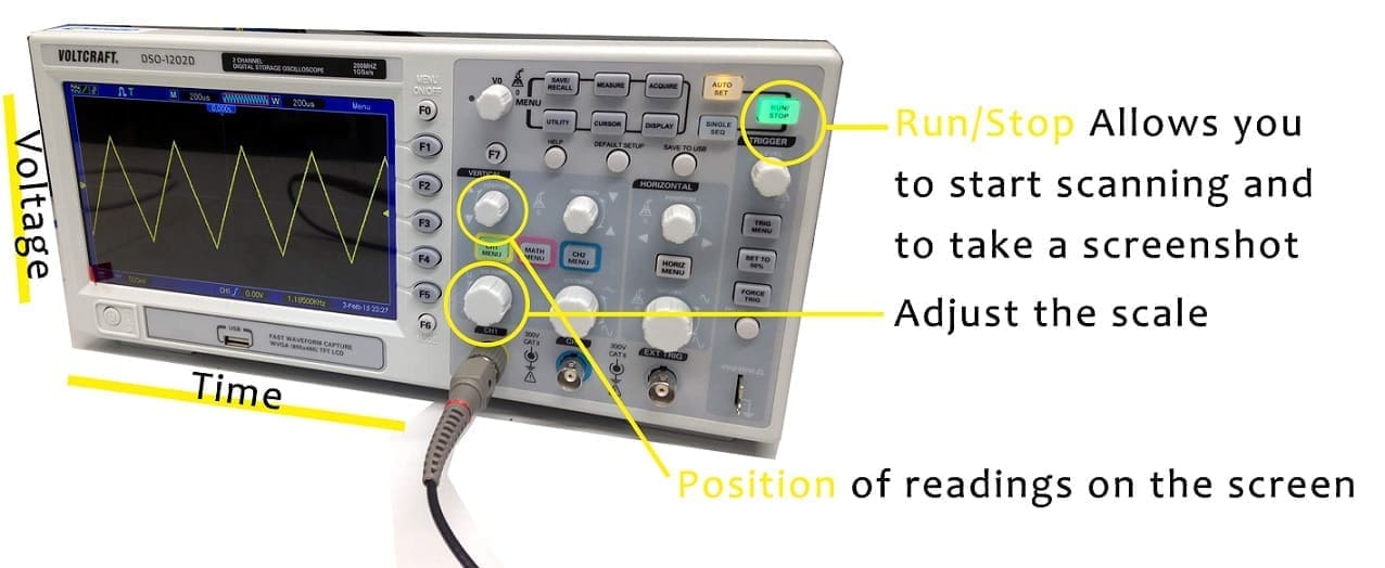
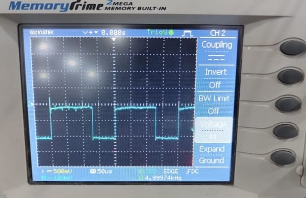
3- Oscilloscope
Oscilloscope allows you to see electric signals as they vary over time on a screen Refrence.
Electronics Design 
Software: Eagle Download Board: ESP32 pinout More details File Download: Schematic & Board design
Eagle 
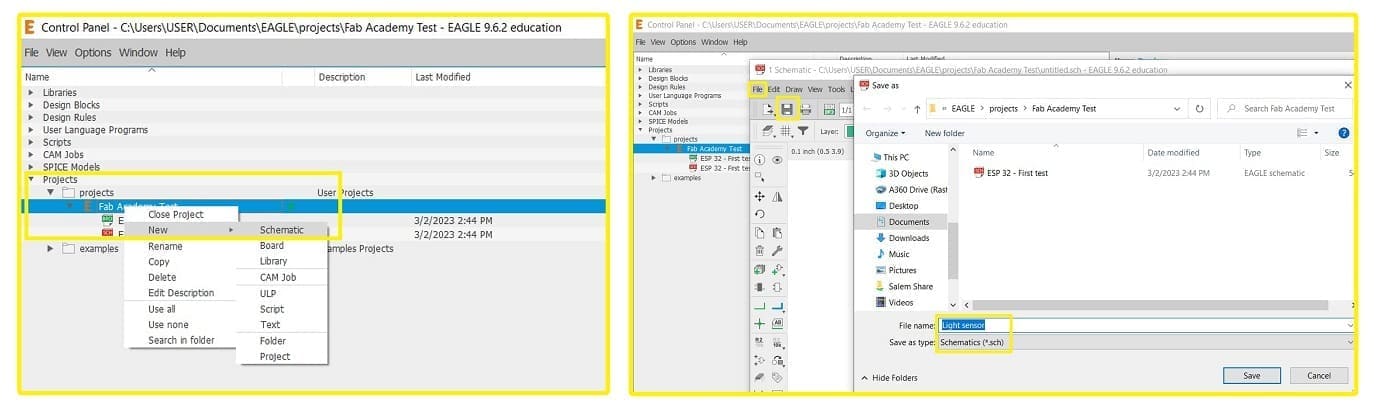
PCB design in EAGLE is a two-step process. First you design your schematic, then you lay out a PCB based on that schematic. in the control panel, choose the Projects folder > right click on Eagle folder > select New Project > give your project a name. right click on your new project > hover over new > click on schematic
Setting up the library 
We are not going to be using the existing Library that comes with the software, therefore; we need to disable the existing one and add another. at the control panel screen under eagle file, press “Managed Libraries” > right click on the folder name and choose “Use none”, download these files (download) and save them on your computer, open documents > open “Eagle” folder > libraries
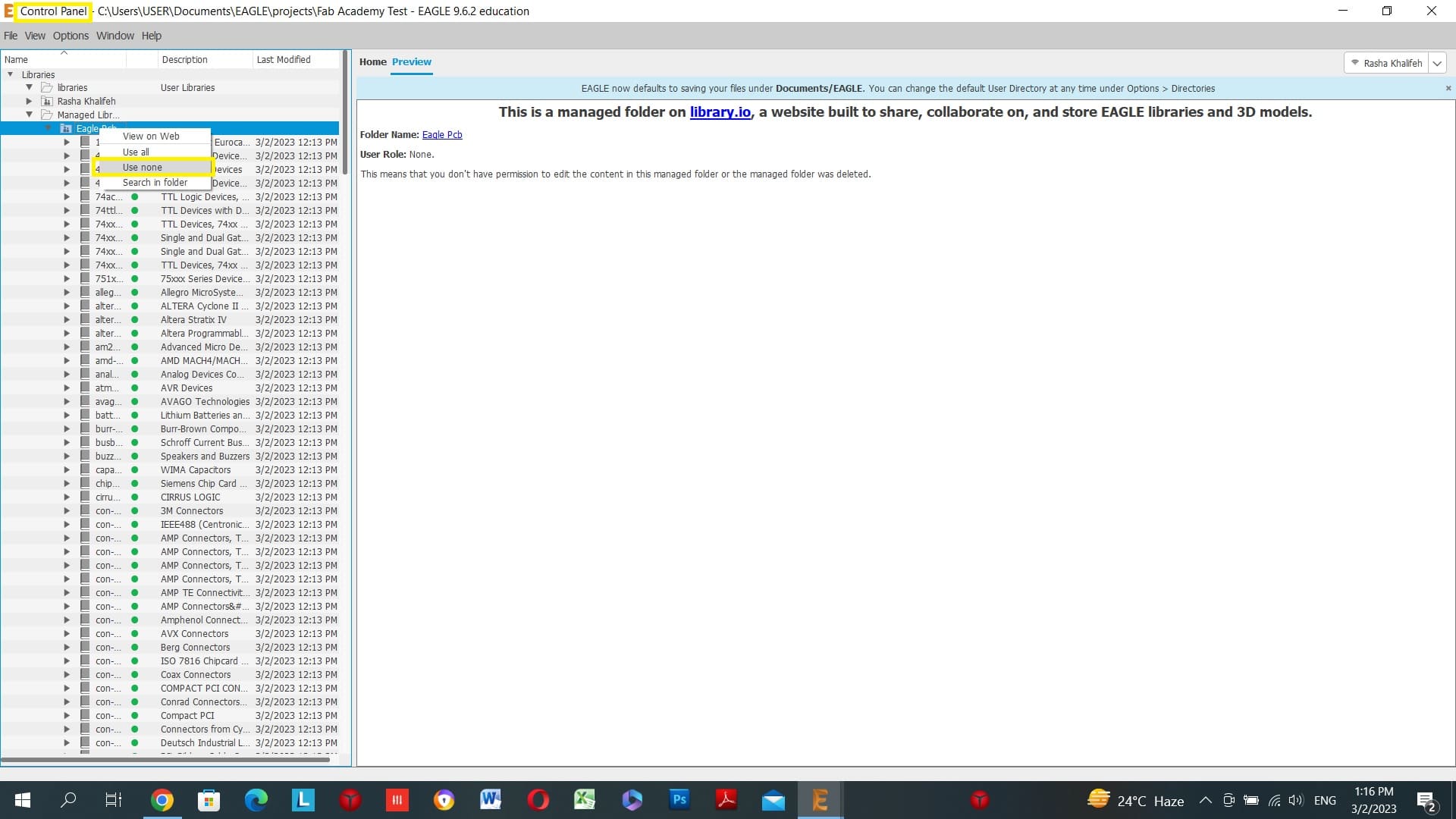
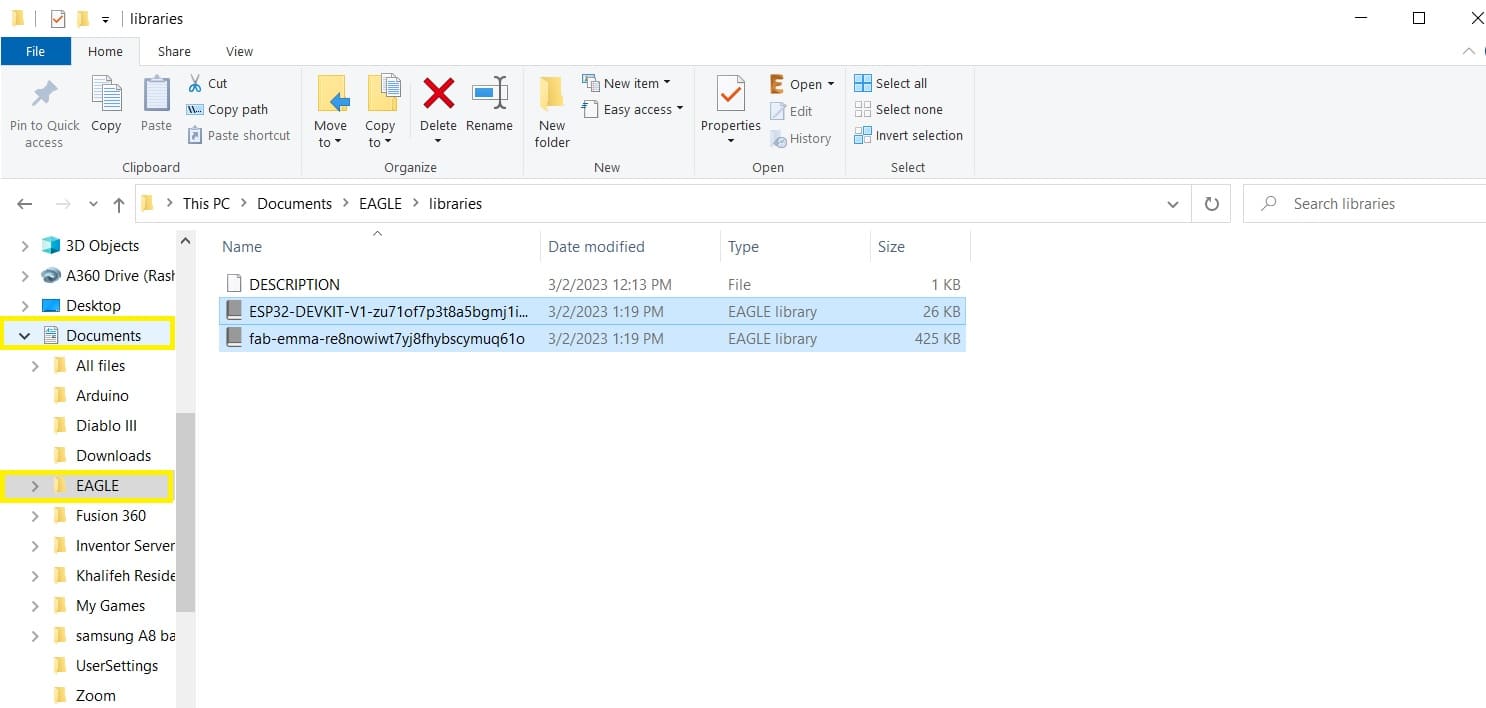
The new folders we installed in our library are available in Fab Cloud and the ESP WROOM 32, Emma provided us with a microcontroller footprint that is easier to follow DOIT ESP32.
After setting up your library, go to control panel page > press on the name of the added library > use, now you can use all of the components in your schematic.
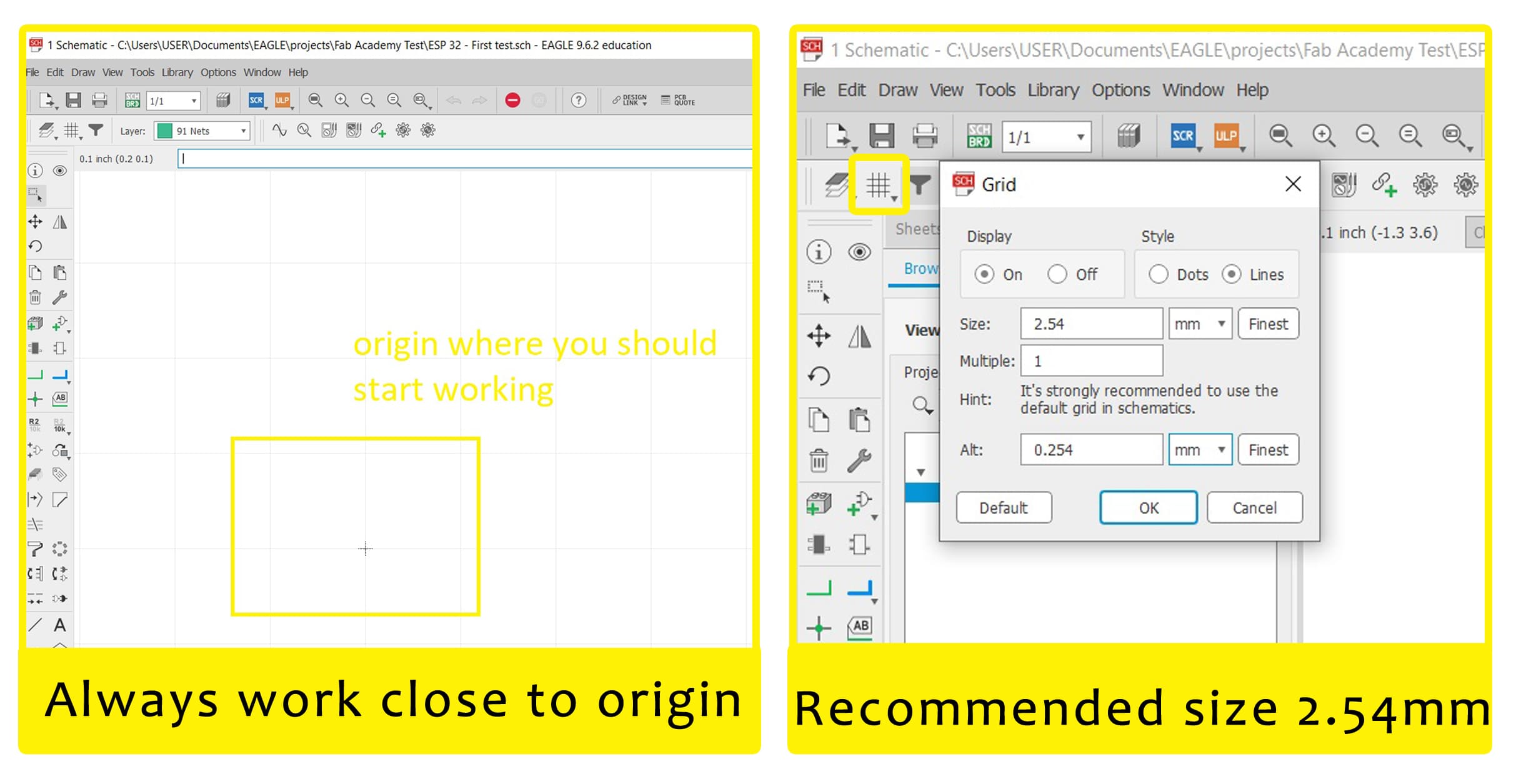
NOTES to work on grid press GRID > it is recommended to work with 2.54 grid size. Also add your elements close to origon point.
Schematics 
Schematics are our map to designing, building, and troubleshooting circuits. Understanding how to read and follow schematics is an important skill for any electronics engineer.
- To start a new project, from control panel page press on File > New > Project, I named it Fab Academy Test -To start a new drawing, navigate above your new project file press right click > New > Schematic.

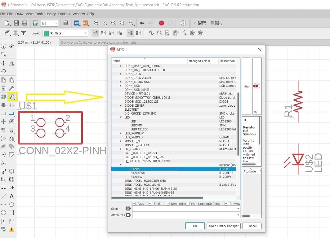
The following image contains multiple symbols used in a PCB board design.
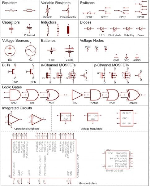
For Adding parts to the schematic, press the ADD tool which will open a Library Navigator press on any part from the library and it will show you the symbol on the other right half of the screen, press on all the elements you need, you can move all parts through the move command which you can type at the search bar.
Wiring up the Schematic 
to add a NET between any two parts, press on the net button, hover over the end of the added part until a circle shows, left-click and follow the green line until you reach the part you want to connect it with.
most commands I used while designing were the following: Net - Delete - Move - Add - value
My PCB design
For my final project, I need to detect motion and make movement in my art installation through my rack and pinion gear. therefore; the elements I need in my circuit are: 1- The Microcontroller (ESP32 pinout) 2- Connector (to connect my sensor to my board) 3- LED
Adding parts 
FIRST Add the needed parts for your circuit and connect them together through NET command. My circuit consists of the following: - DO IT ESP 32. - Led lights. - Resistor. - Connector with 4 pins that will be connected later on to the HC-SR04 Ultrasonic distance sensor.
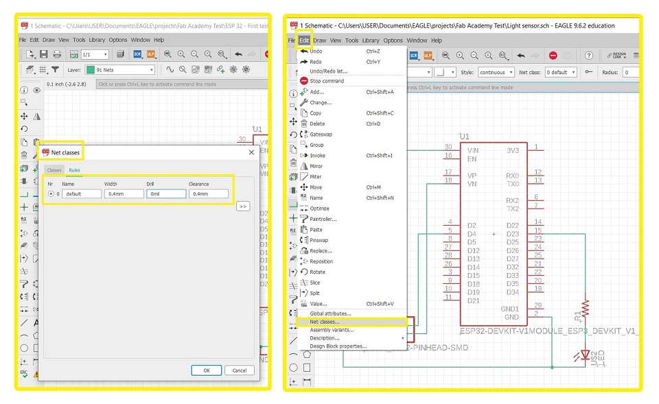
 SECOND modify the net thickness between the parts go to edit> Net Classes > modify numbers as needed.
Net classes I set thickness of the tracing network to .4mm because the endmill I am using is .4mm shown in the picture above.
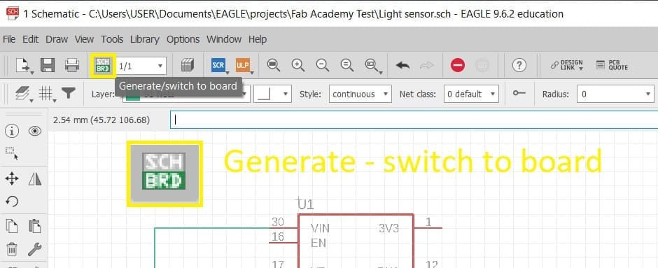
 THIRD Generate board from sketch
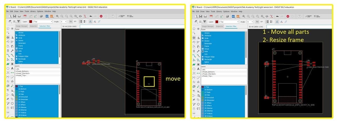
 Fourth move parts & resize frame.
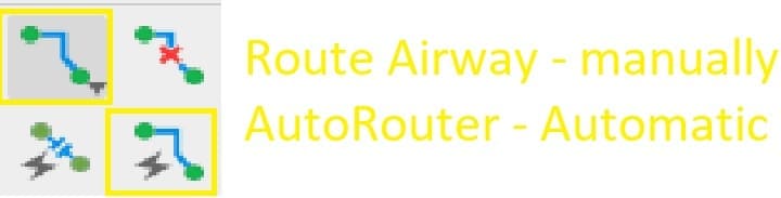
 Fifth Routing - Either manually or automatically.
NOTE: After running the DRC check, I realized that I should never trust the automatic router! always connect wires manually! much easier and simpler.
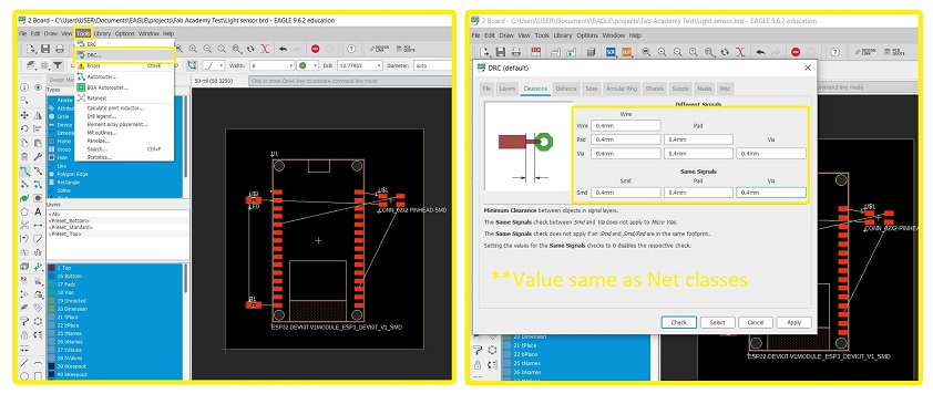
Sixth DRC - Design Rule Check - this command willcheck my network instead if there are any overlaps or ripped wiring in my design.
Go to Tools > DRC > Clearance. Modify clearance to the same value as net classes. which is 0.4mm clearance and press apply
Now you can run the DRC check.
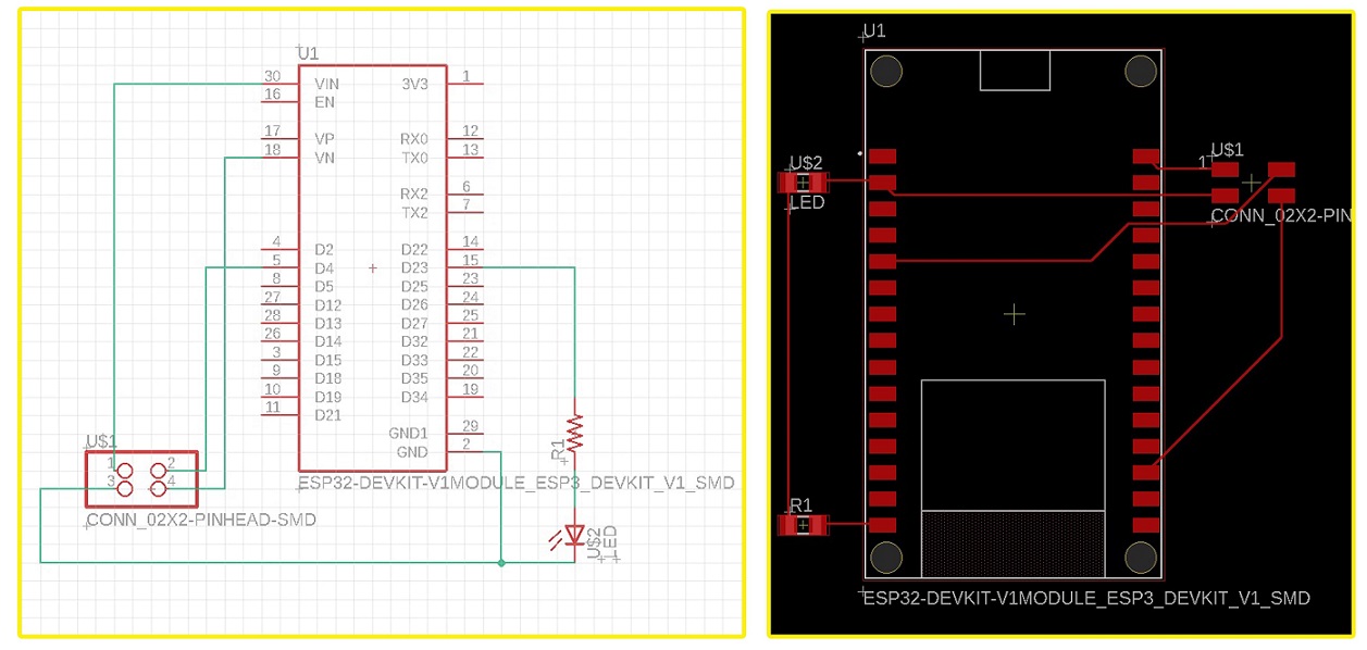
Final Board Design
-Schematic to board design
Group assignment
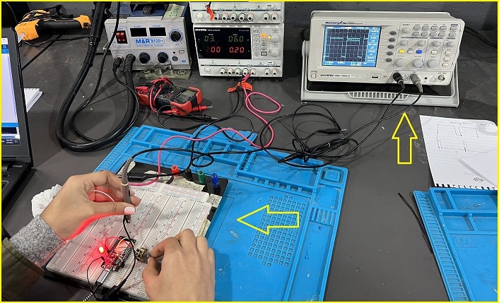
In our group assignment we tried all three machines, at the Oscilloscope we tested a circuit with a Potentiometer and a LED first we created the circuit, then we used Arduino program to code our sketch and saved it on our PCB, then we connected our circuit with the machine, at first the reading was not correct because we found out the sketch was supposed to have a “map” value so the potentiometer can give a correct reading.
The code we used on our microcontroller:
 int ledPin = 16;
int sensorPin = 36;
int sensorValue=0;
int outputValue=0;
const int freq = 5000;
const int ledChannel = 0;
const int resolution = 8;

void setup() {

  pinMode(ledPin, OUTPUT);
  pinMode(sensorPin, INPUT);
  ledcSetup(ledChannel, freq, resolution);
  ledcAttachPin(ledPin, ledChannel);

  Serial.begin(9600);

}

void loop() {

  sensorValue = analogRead(sensorPin);
  outputValue = map(sensorValue, 0, 4095, 0, 255);
  ledcWrite(ledChannel, outputValue);

  Serial.println(outputValue);

delay(100);
}
We also tested the Multimeater, by connecting the ports to different wires in a circuit you can measure voltage, current, resistance and capacitance. we tested the continuity mode on several circuits to test if there is a short.
Useful links
Learn About Multimeters Digi-key ESP32 Pinout Board Designing a circuit Tutorial Eagle Board Design