Computer Controlled Cutting
Welcome to week 3
Key Learnings For this week I used two machines for the first time in my life! the Laser cutter and the Vinyl cutter! I absolutely enjoyed both! I am also getting familiar with Fusion360 and Inkscape while sketching my assignments which is taking double the time! too many things to learn in such a short time.
The Vinyl Cutter
- Machine used : Roland link
- Programs: Cut Studio
Cutting blade
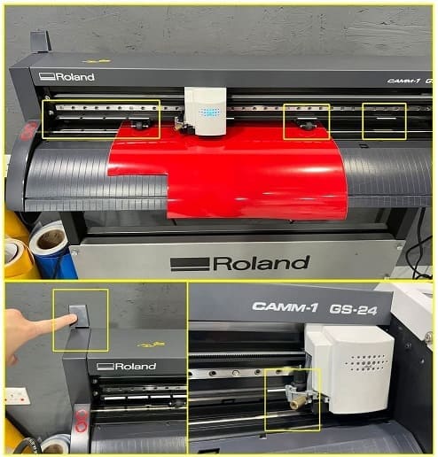
I rotated the blade holder cap and removed blade from its place to test sharpness of the blade by finger. when putting it back I tightened the screw to hold the blade holder firmly (As shown in picture). Press move to place it on the side of the paper.
Placing The Vinyl Roll
After pushing the handle lever shown in picture to the back you can remove and add the roll or a piece of vinyl manually from the back of the machine by placing it on the metalic bars. the Vinyl paper can be inserted under the cutting blade and must be fixed in place by moving the rollers in between any two white strips on machine, the machine will measure width of the vinyl paper before starting the job.
Machine Set up
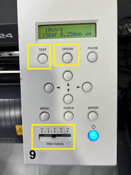
Turn Machine On, press “origin” button so that machine can specify vinyl location according to the two rollers holding the vinyl paper. select type of sheet (mine was a piece), now the machine will measure working width of the paper using the rollers.
Testing Pen Force
Before cutting my sticker I tested the pen force, the correct force when blade is cutting the vinyl sticker without cutting the paper on the back press on test the machine will cut a pre-defined shape, if the cut penetrates into the back paper of the sticker decrease force. the right force for my vinyl sticker was 0
Design a sticker and cut on Vinyl
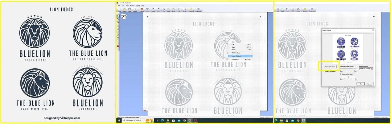
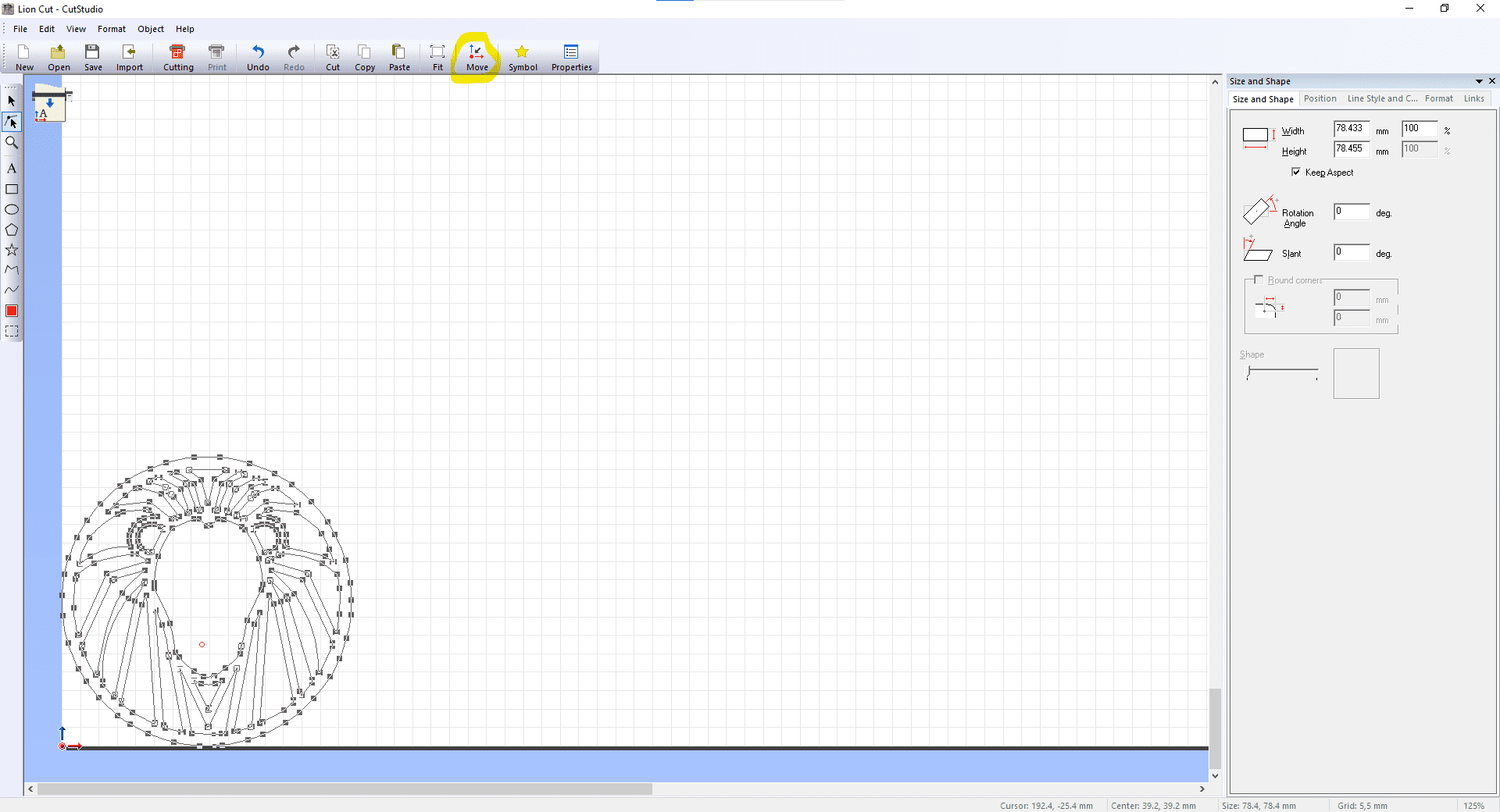
For the design I downloaded a vector from this website Freepik I opened Cut studio program which is operating the machine. I opened the design through the cut studio software, I pressed right click > Image Outline > Extract contour lines > ok, the vectors were outlined now and ready to cut. I resized them and placed them at the bottom of the vinyl paper through clicking on move. I pressed Ctrl P and the machine cut the shape.
Using the sticker
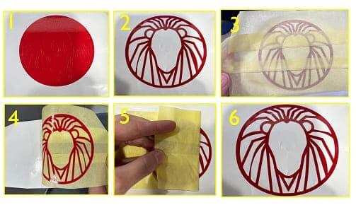
After sticker was cut. first thing you remove the frame of the sticker. then using a tweezer I removed all unwanted parts of the sticker! I accidentally removed the eyes of my lion!! oops!
I then placed my transfer tape on top of the sticker (don’t push too strong on sticker) and I had to use multiple transfer tapes by overlapping them with each other. I removed the transfer tapes with the sticker from the white background paper and then placed it on the surface where I want my sticker (My notebook) Then I removed the transfer tape slowly and horizontally not vertically on surface.
Laser cutting
- Machine: Trotec
- Programs used: Fusion 360 - Inksacep
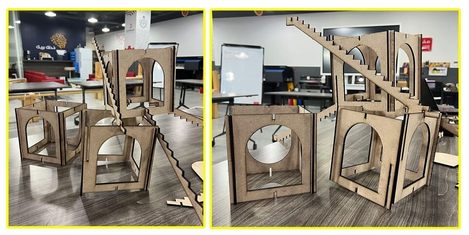
- Mission: Design a Press and Fit Parametric shapes
- File Download: Parametric shapes for laser cutting
- Vinyl Cutter sticker: lion sticker
- Group Assignment: engrave test
- cut test
- Kerf test
- Joint test
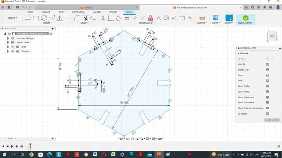
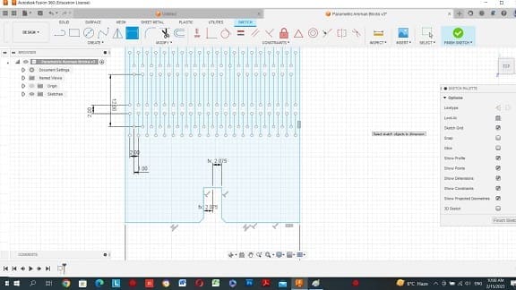
Preparing 2D drawing in Fusion360
Fusion 360 has a great command for pre-identifying of dimensions to modify sketch easily if needed.
I identified Thickness of the joints according to the material I am using (MDF wood 4.3mm), I also identified the Kerf value according to the test we did in our group assignment (Best Joint fit value is .13mm) (kerf value is .02). I subtracted the two values from the board thickness through the parametric command and that was my pre-identified thickness for the press and fit openings. Save File with DXF extension so we can open it in Inkscape.
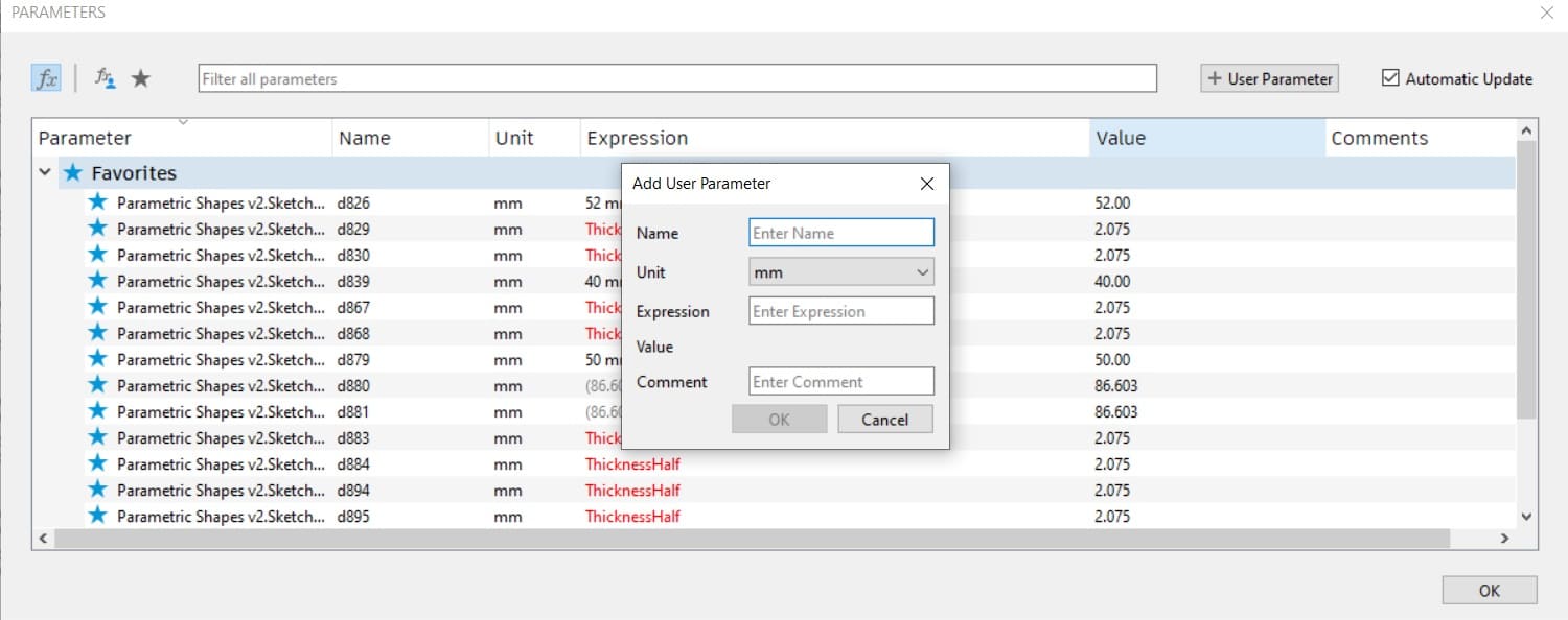
To make your design Parametric press on Change Parameters
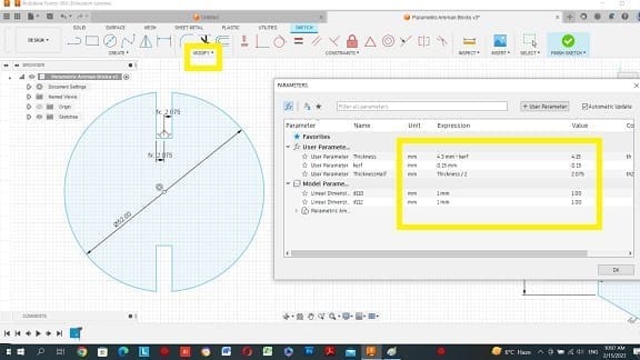
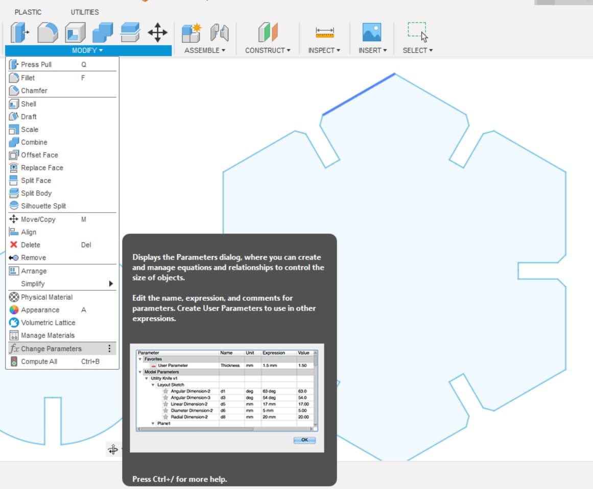
a window will appear, press on user parameter identify name and thickness.
whenever you need to change thickness you can go back to this parametric value and change the number, the value will change in your design automatically.
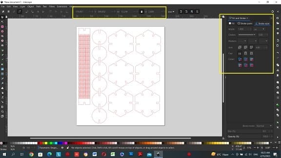
Preparing 2D drawing in Inkscape
Open saved file in inkscape, I checked drawing Size first thing which wasn’t correct. I changed it from the bar above by multiplying with ten. I rearranged the shapes to maximize space. changed color of the lines to become red (RGB, 255,0,0) stroke only with no fill, I also changed the thickness of the lines for 1 px.
Press Ctrl P and choose the laser cutter.
Laser cutting Software
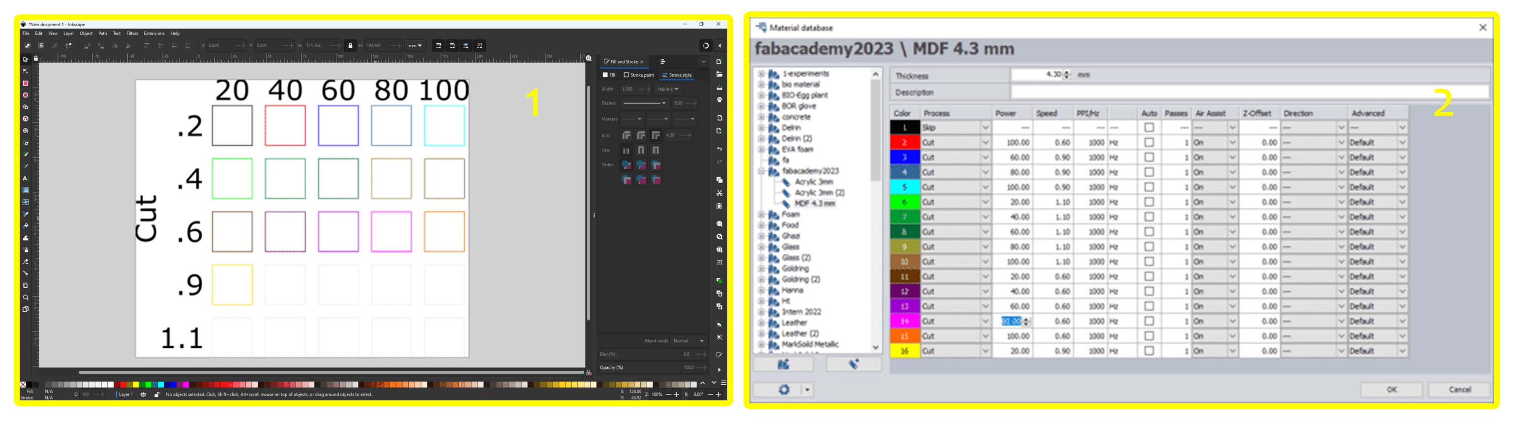
The drawing is now uploaded into the laser cutter software. I chose the material I am using and thickness.
The laser cutter reads required jobs according to colors, because I assigned red color in inkscape I altered power and speed in the red color box. According to the test we did in our group assignment, the best cut power 75 and speed was .3 for this particular material and thickness, I assigned these two values for cutting the shapes, pressed update.
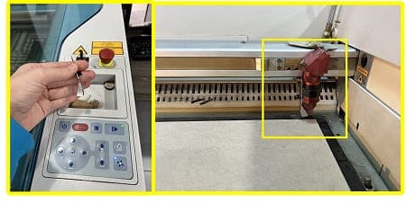
Laser Cutting Machine Set-up
Make sure machine is on and most importantly make sure ventilation system is on too! place your board on the machine bed, move laser head to the corner, place “focus tool” on the laser head and move laser bed up until it touches the material and falls off! once this happen your laser is focused correctly you can now start the job from the laser software.
NOTE Stay close to your laser for the entire time it is cutting!!
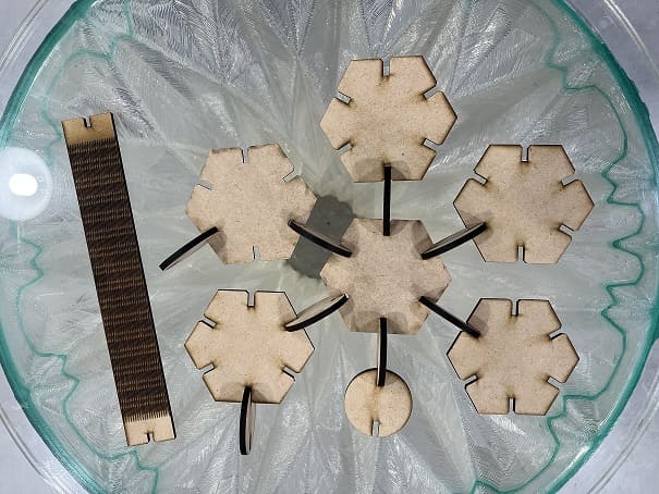
the elements I designed were interchangable! but the flexible part I cut was not correct! I was supposed to draw the lines in the other direction! so it was not flexible it was just a rectangle with pattern on it!
Group assignment
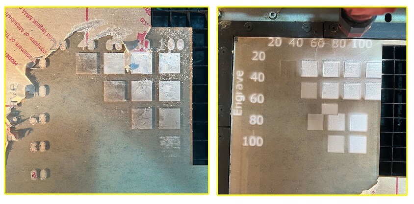
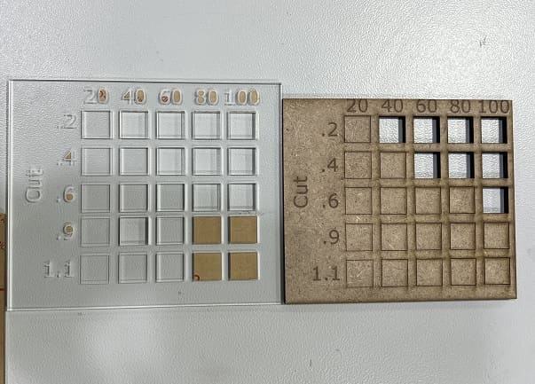
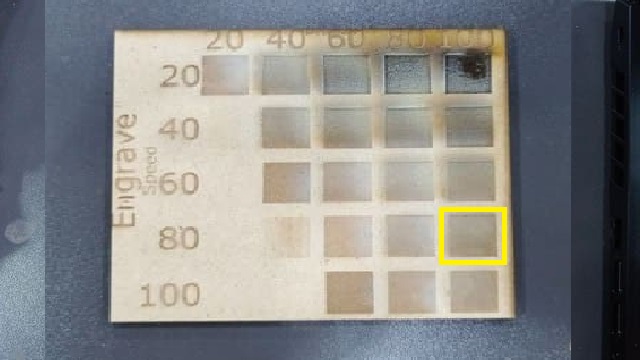
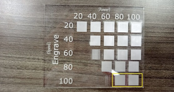
Testing optimum power and speed on different materials
We prepared files for the machine by drawing rectangles on inkscape and identifying power and speed, we colored each rectangule with the assigned speed and power for cut & later engrave value.
We tested cut and engrave on both wood and acrylic material. from our test we learned that the best results for power and speed is as follows:
- Cut
- Wood 4.3mm: optimum speed= 100 Power=.6
-
Acrylic 3.00mm: optimum speed= 100 Power =.6
-
engrave
- Wood 4.3mm: optimum speed=100, Power = 80
- 3mm acrylic: the best values were Power=100,speed:100
Joint fit
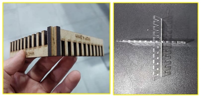
- 4.3mm MDF : 4.3mm
- 3mm Acrylic : 2.7mm
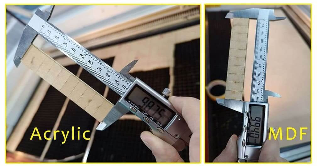
Testing Kerf
To calculate Kerf, we drew 10 rectangules attached to eachother and cut them equaly, we took measurement before and after cutting the 10 equal rectangles for both MDF and Acrylic.
MDF Kerf = ( Designed Length - Actual Length ) / ( number of vertical lines ) Kerf = ( 100 - 99.4 ) / (11) = 0.055
Acrylic Kerf = ( Designed Length - Actual Length ) / ( number of vertical lines ) Kerf = ( 100 - 98.75 ) / (11) = 0.114
My Errors taught me
learning on new machines and new software for the first time I made many mistakes! 1- I thought I understood what a parametric design is until I realized I was using the wrong method to draw my shapes! I found out I should have pre-determined the thickness through the parametric command shown above. 2- I designed a whole kit and redrew it multiple times (so much wasted time!) and after cutting it I realized it’s two big and it cannot be fixed the way I imagined it to do!
3- While testing the power and speed, we should have removed the paper on before engraving because the machine engraved the paper