WEEK 7. Computer controlled machining
assignment - group assignment do your lab’s safety training test runout, alignment, fixturing, speeds, feeds, materials, and toolpaths for your machine
-
individual assignment
make (design+mill+assemble) something big (~meter-scale) extra credit: don’t use fasteners or glue extra credit: include curved surfaces
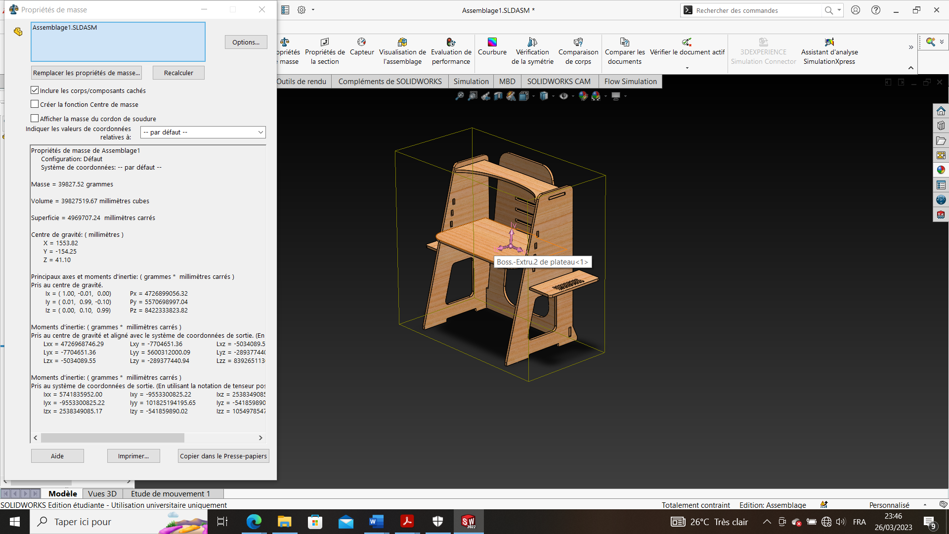
For this week I will design a table that can modify the level
1 Design
-
software

To draw on SOLIDWORKS you must follow these different steps:
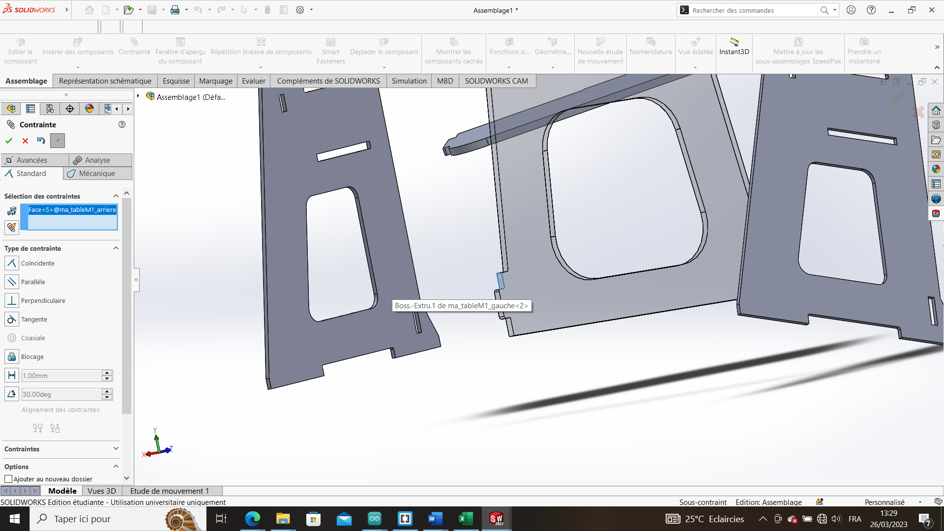
0- Open the software and choose New Part

1- You must create the sketch using the Sketch tab;

2- It is now necessary to create the constraints,
that is to say to put the odds.
And as these parts will be assembled without the use of screws or glue,
geometric tolerances must be provided;

3- We now move on to the extrusion of the part in sketch,
this time the extrusion top will be the thickness
of our material used.

4- If this part is finished, the same procedure must
be used to produce each part.
in order to obtain all the parts

5- If all the parts are made then they must be assembled
to see the errors
and correct the adjustments for example.
For each piece it is necessary to register
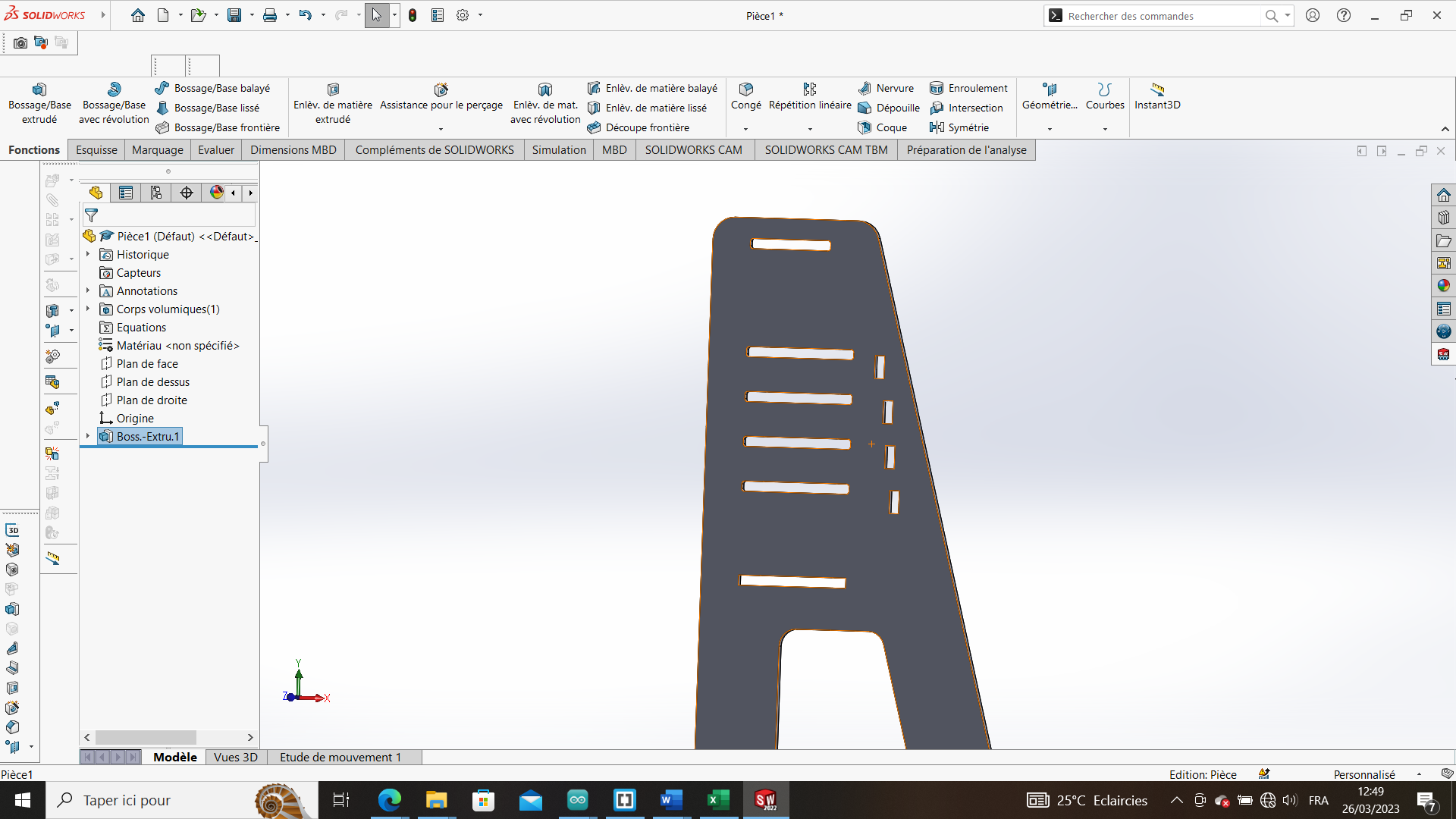
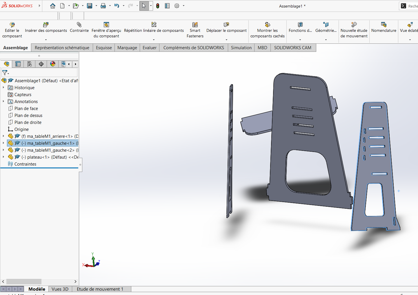
here are the different steps of designing the parts of my table on SolidWorks!
– The image below explains the design stage deferents
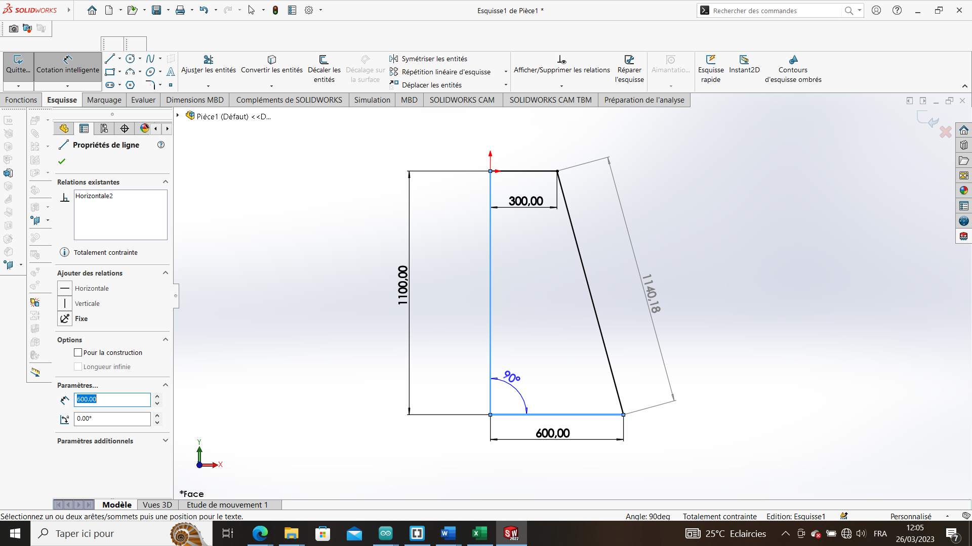
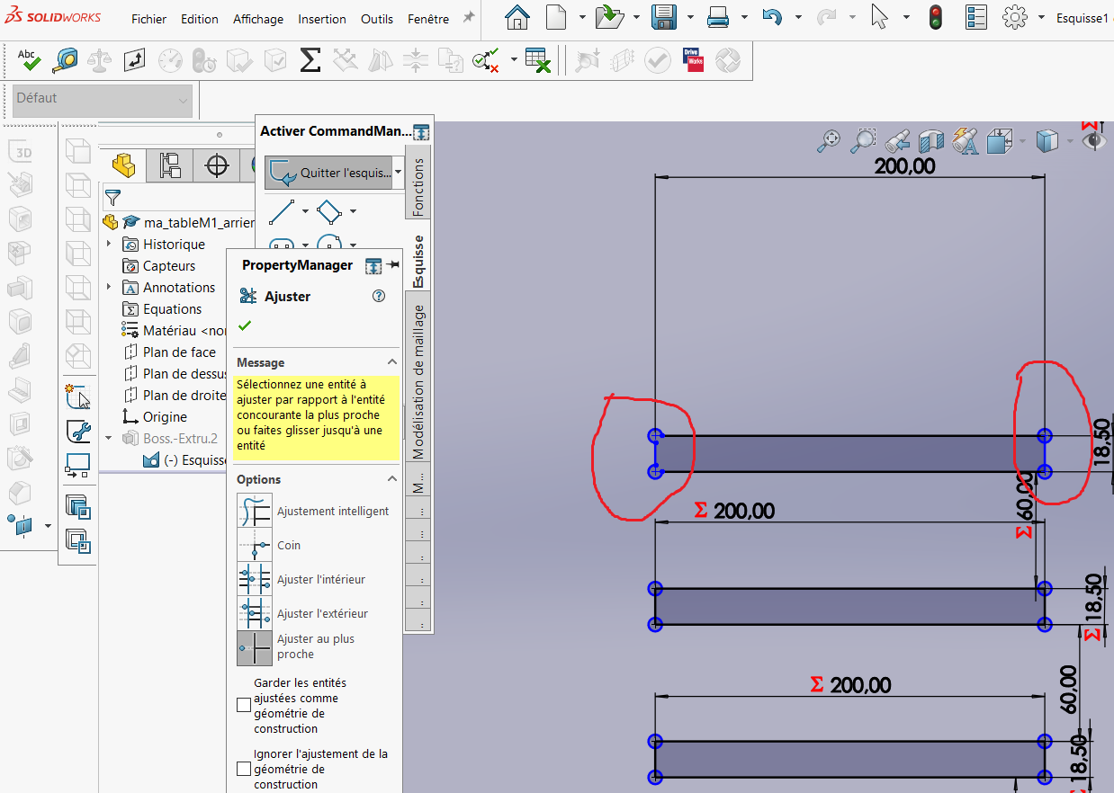
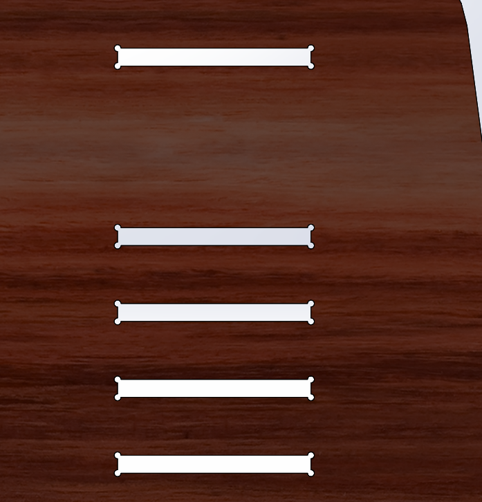
1 - Creation sketches
here I put my settings odds
2-
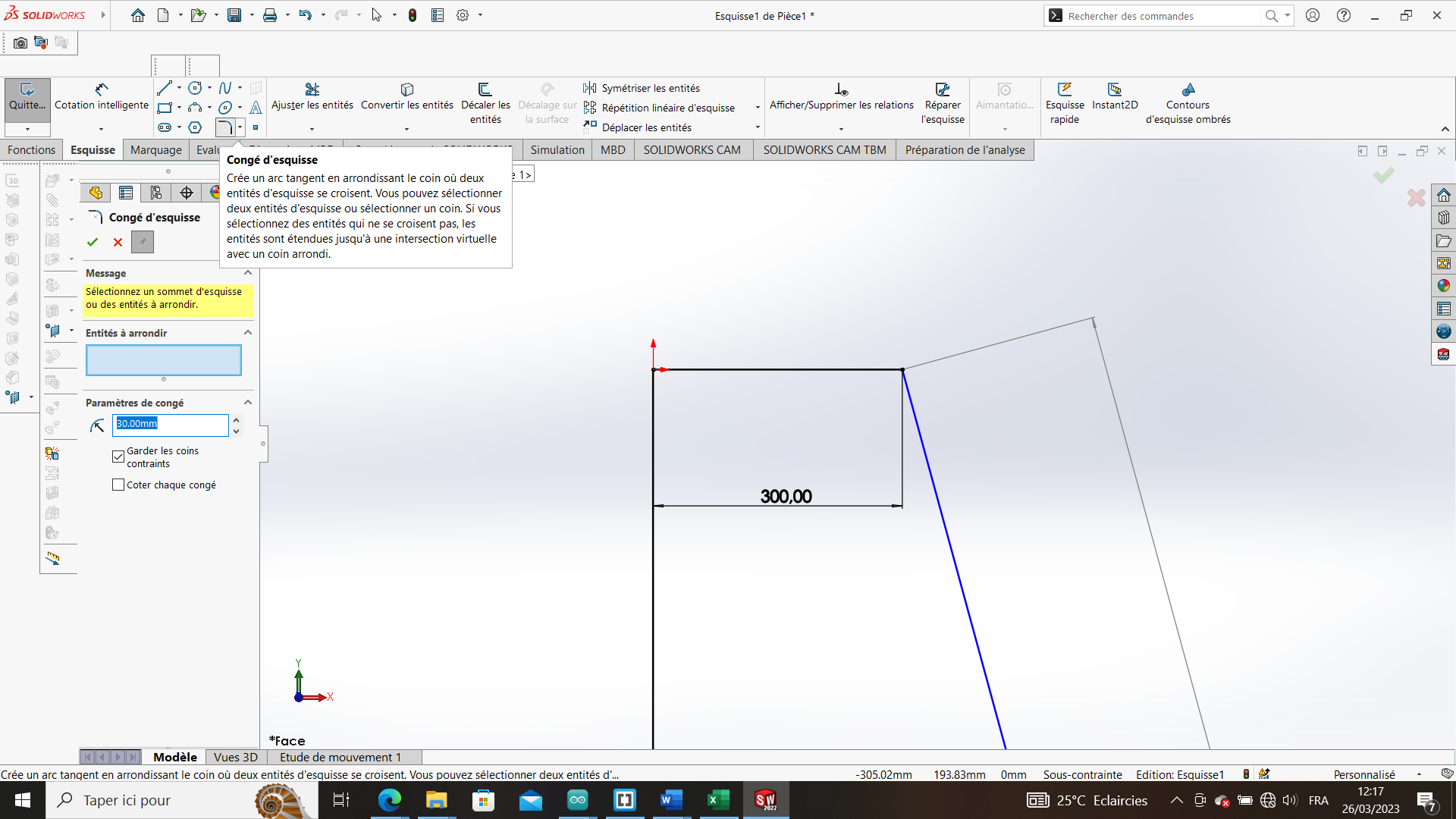
3-
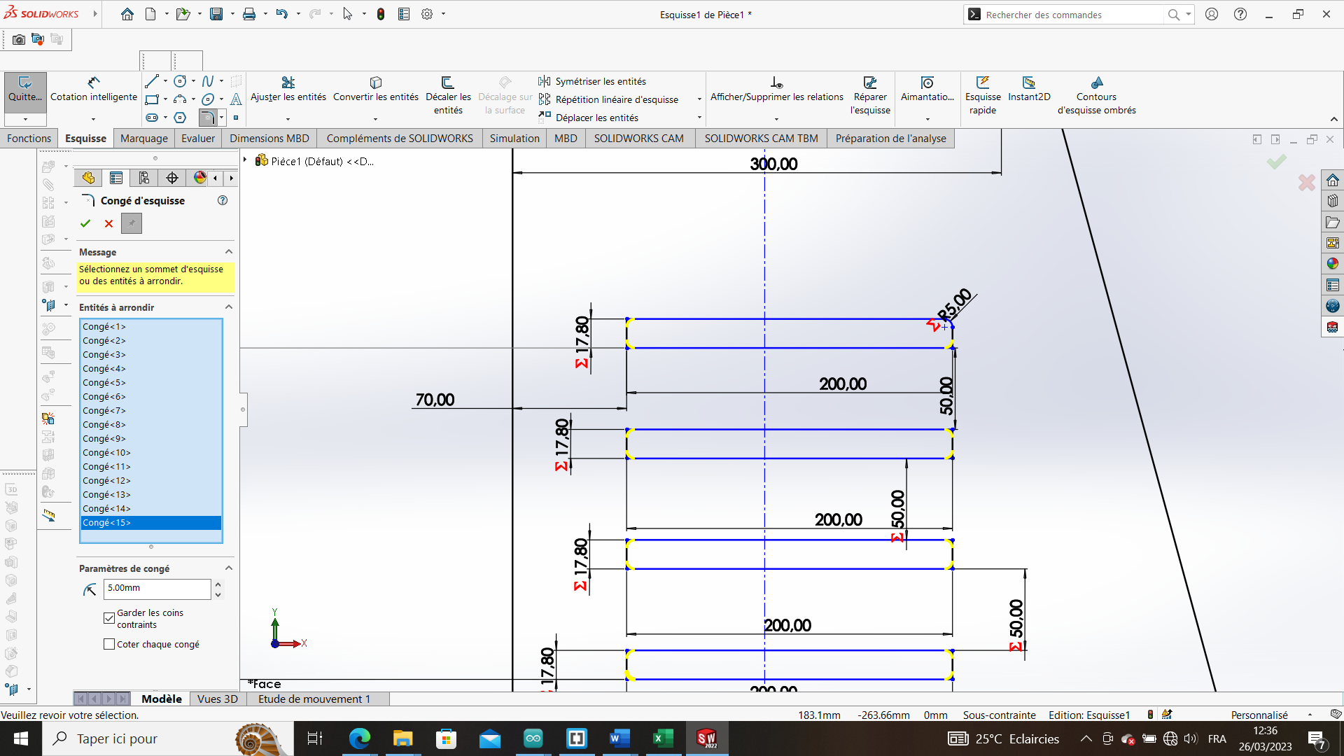
4-
 5-
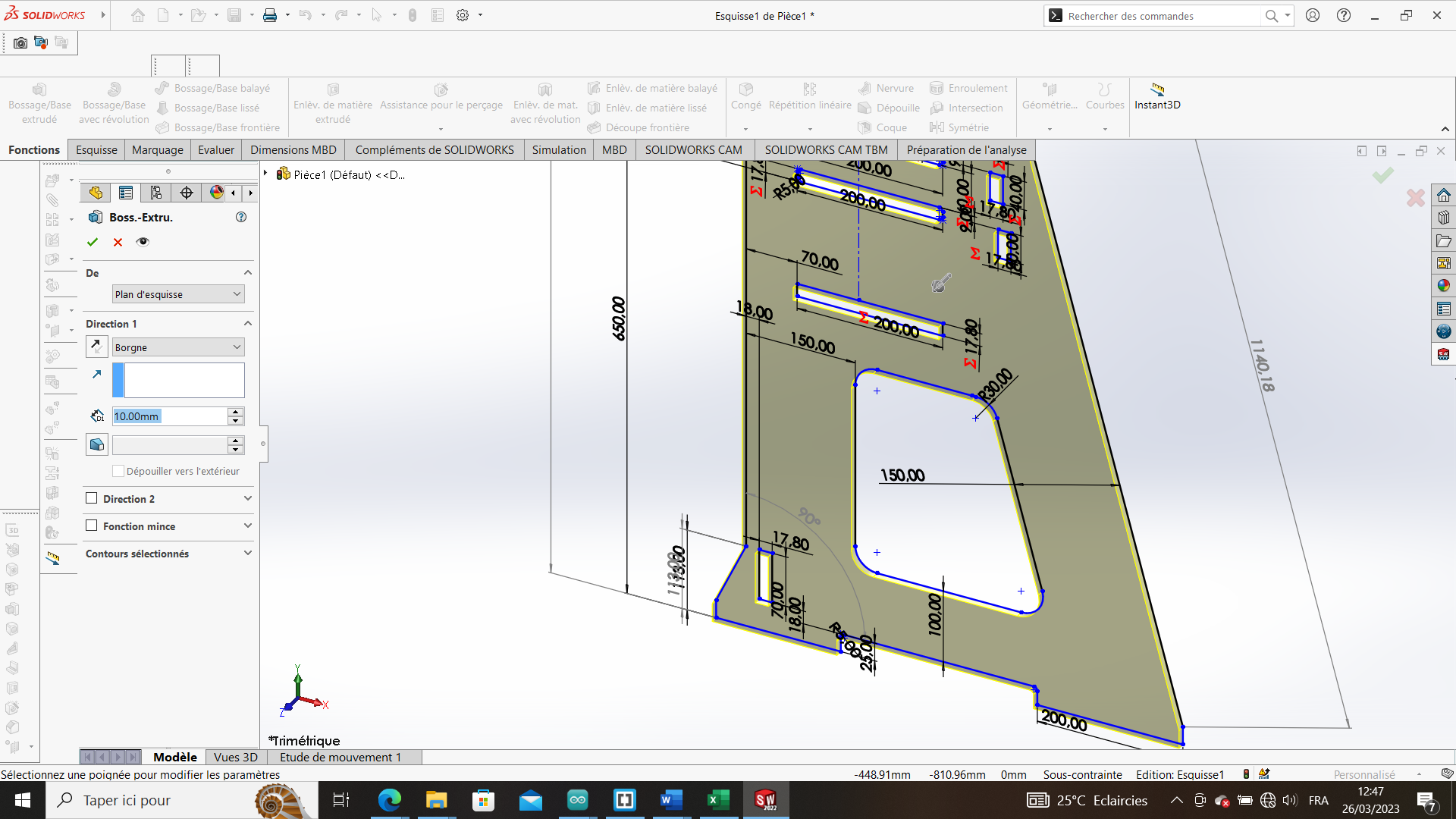
5-
6-
7-
 8-
8-
SAFETY
- [X] For MAN
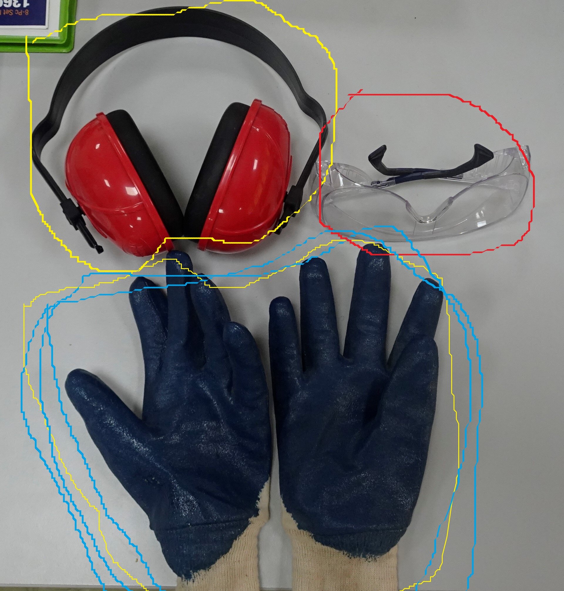
the essential protection tools are :
        - Surrounded in red are the wood chip protection bezels.
        - Surrounded in blue are protective gloves.
        - Surrounded in yellow are the anti-fog helmets.
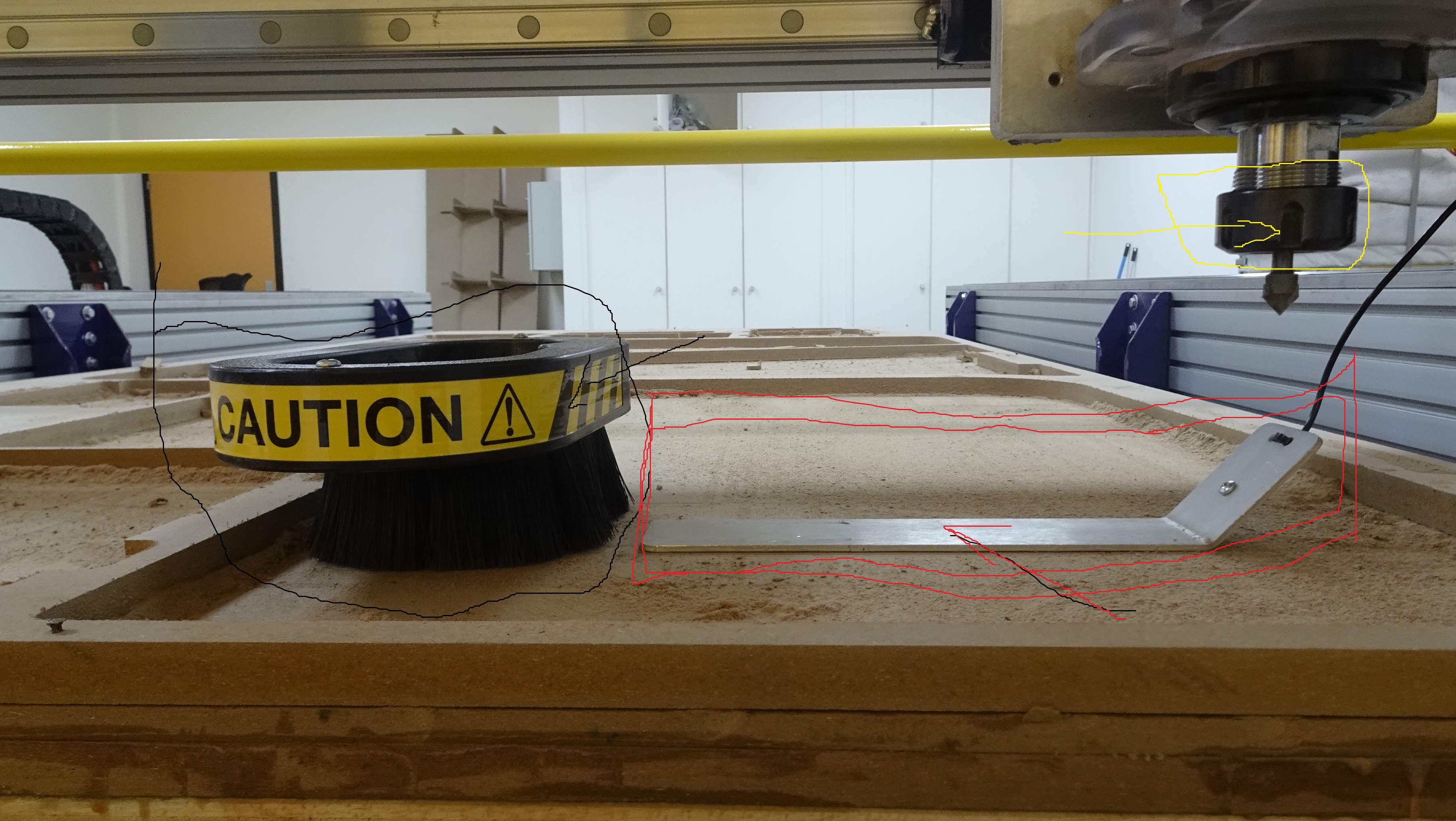
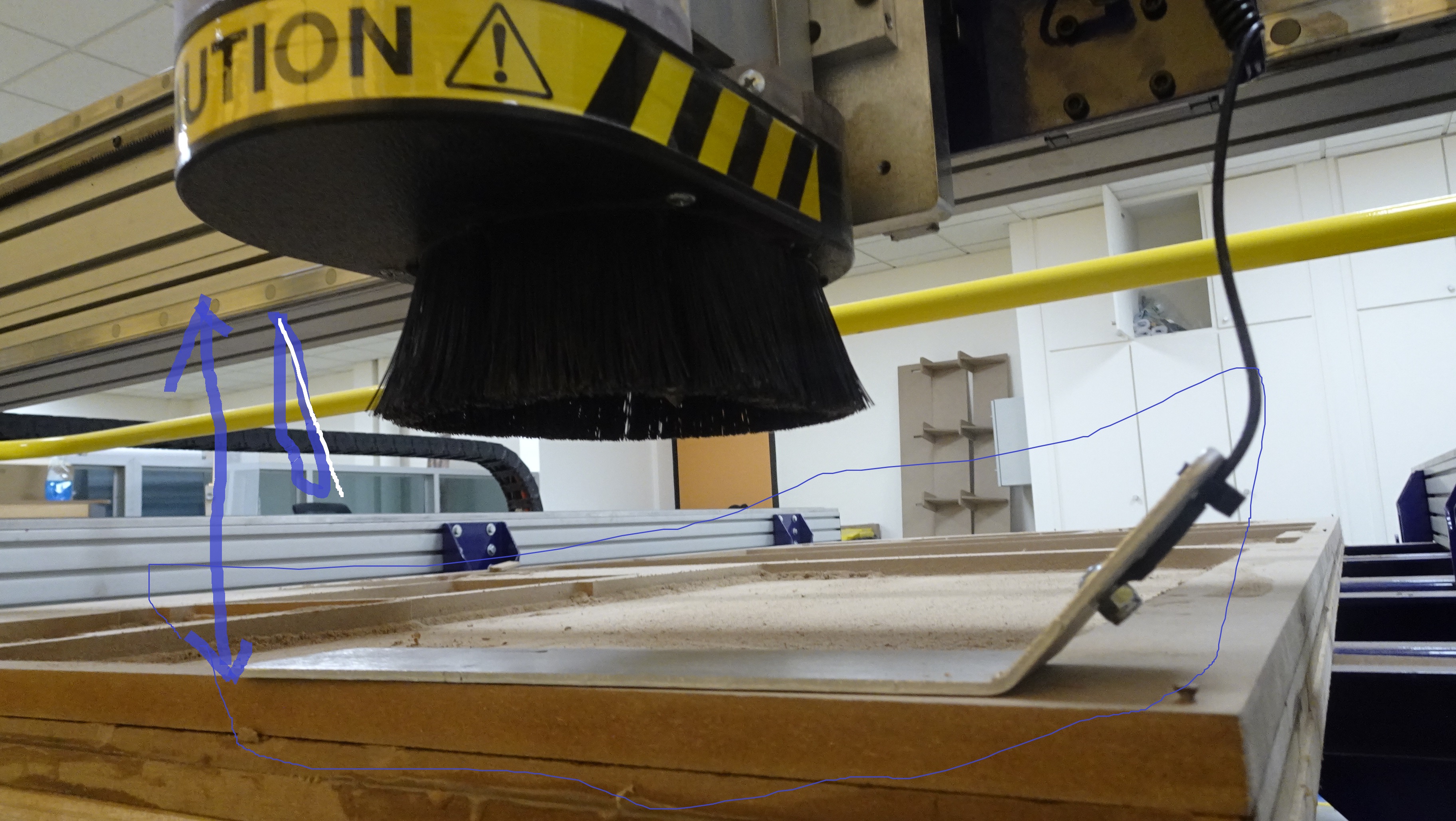
- [X] For Machine
    - the metal plate is very important for the W zero.
    - be sure to remove it after a Z zero.
    - Then position the chuck and tighten the cutting tool.
ESSENTIAL ITEMS TO CHECK BEFORE STARTING UP THE MACHINING SPINDLE.
Tool parameters
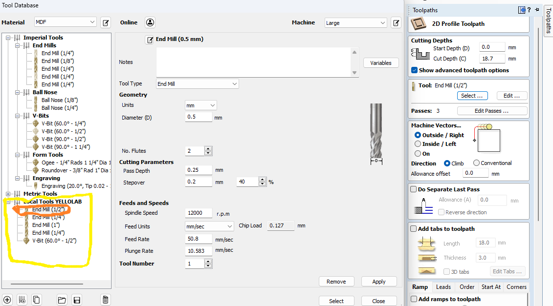
What i learned
- I learned how to: -Parameterize a new tool; how to hack a new tool in such a way as to retrace the toolpaths.
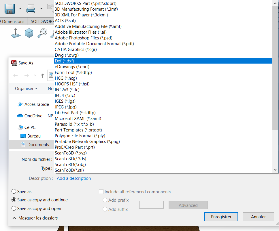
Cutting Files
to obtain the cutting file, save as on solidWorks and use the DXF format
1- save the file as DXF file
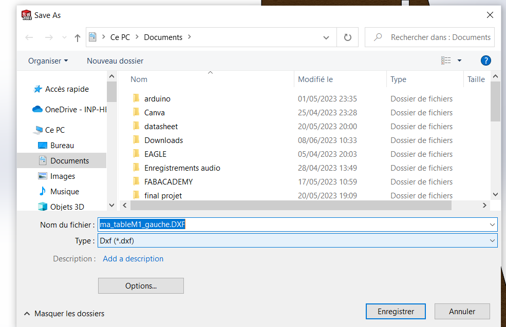
 2- choose a folder
2 Milling Process

before proceeding to the machining of our parts we will proceed by generating the toolpaths on the Vcave software.
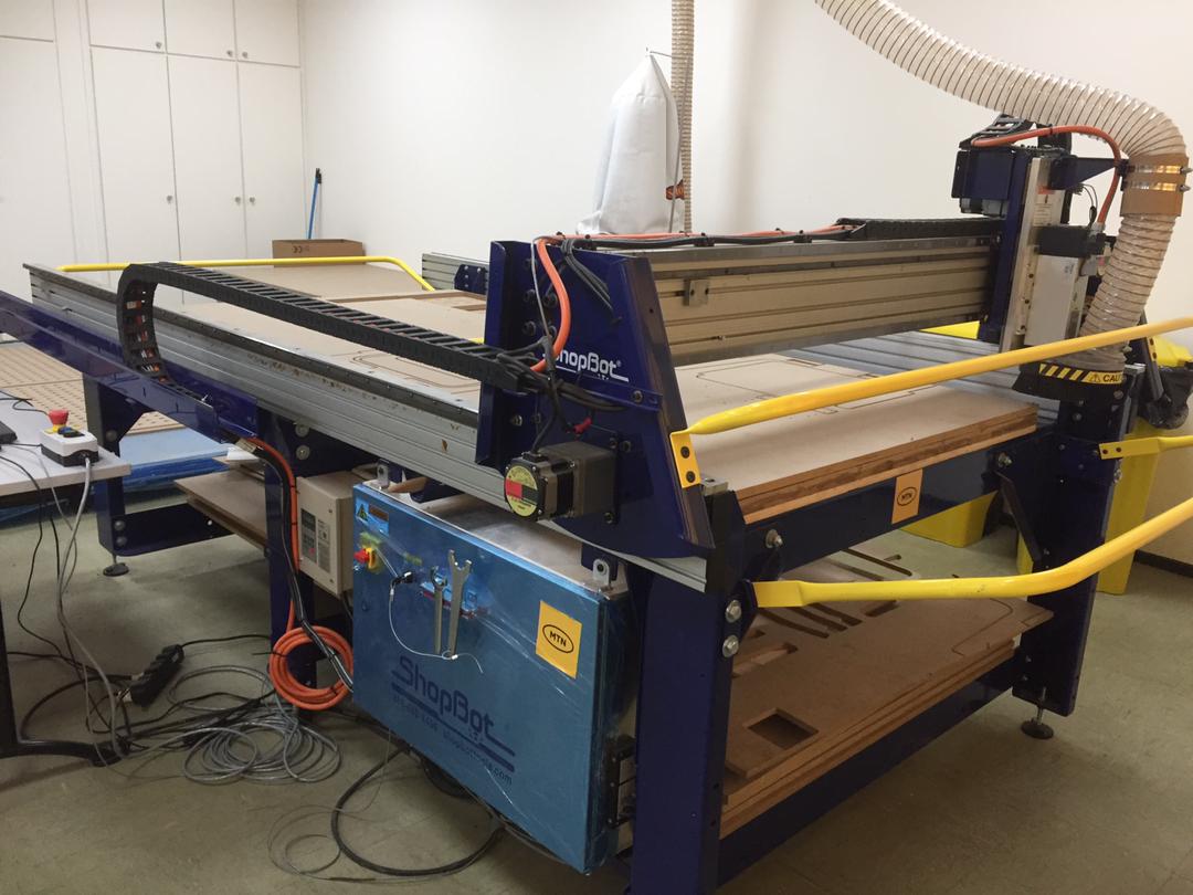
- machin

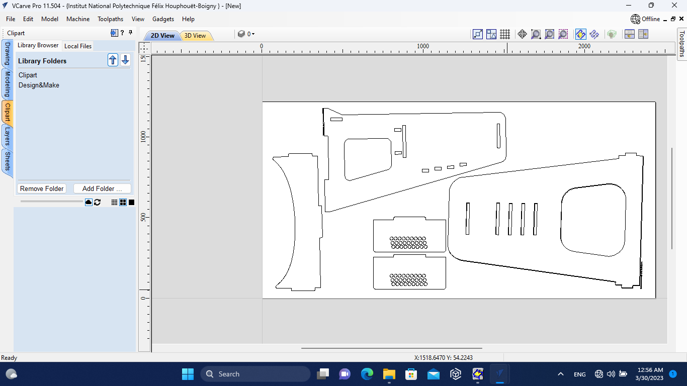
here I place the parts on the machine's workspace.
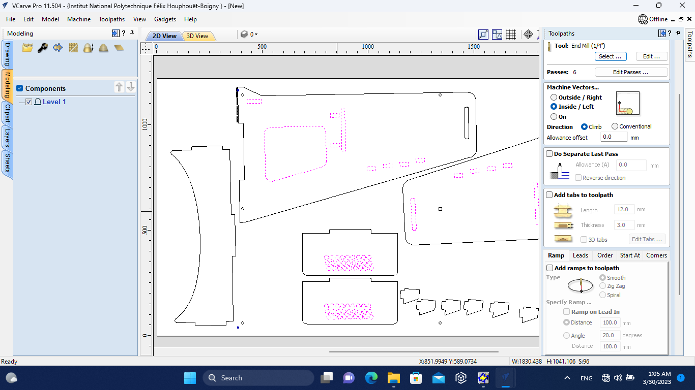
now we move on to the settings for generating toolpaths
- for the toolpath, for drilling and material removal the tool passes inside and for contours the tool passes outside.

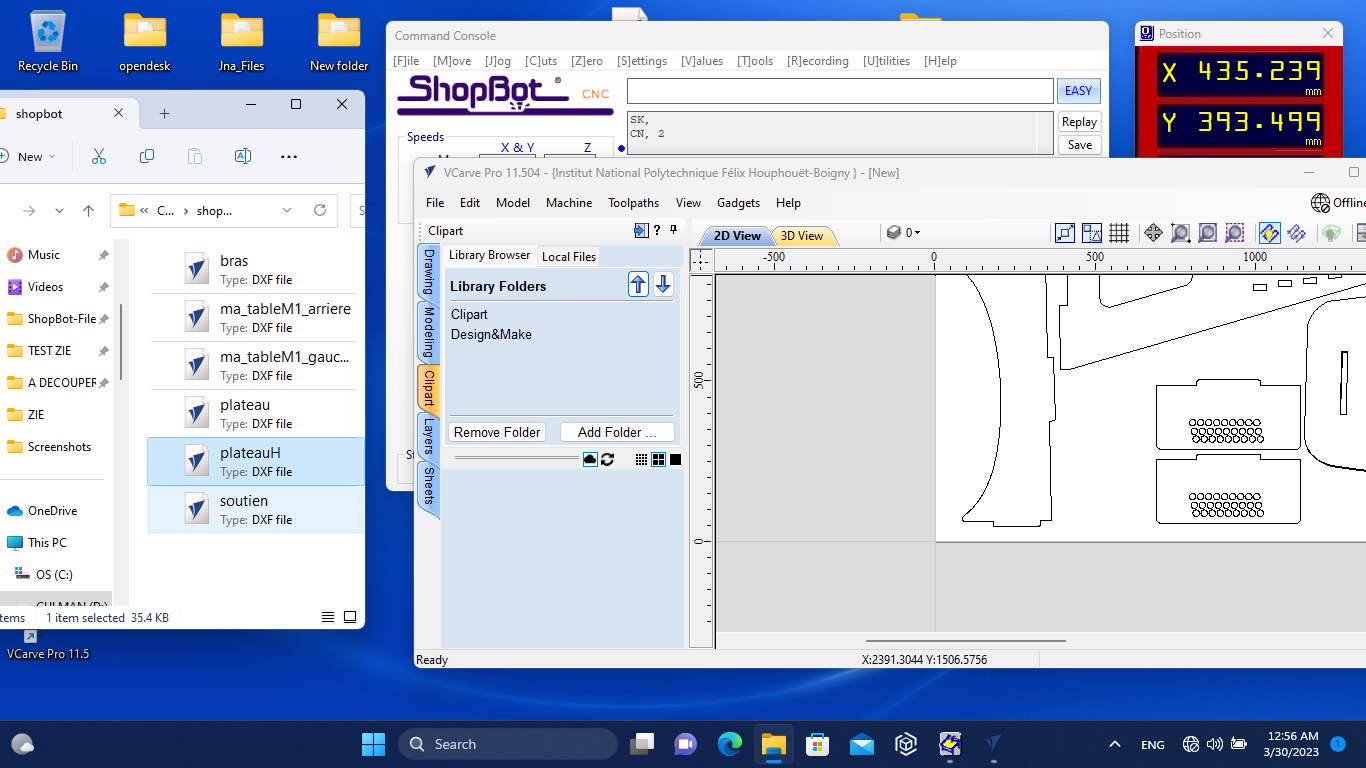
we now move on to calculating the toolpaths for the Shopbot
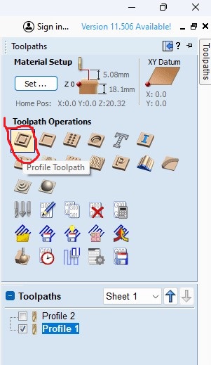
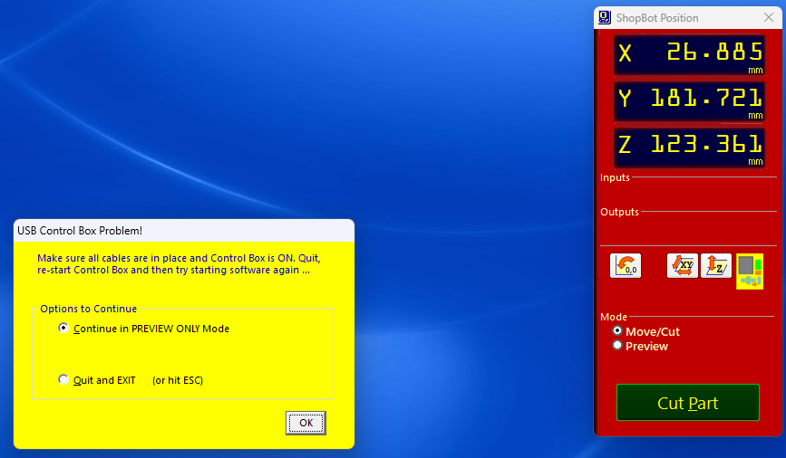
Then we can go to shopBot machine to begin the milling production.
THIS IMAGE show HOW IT IS POSSIBLE TO IMPORT FILE IN THE SHOPBOT SOFTWARE IN DETAIL Anyway don’t forget to set the Y and X zero then Z zero. however you chance material you have to make this operation again.

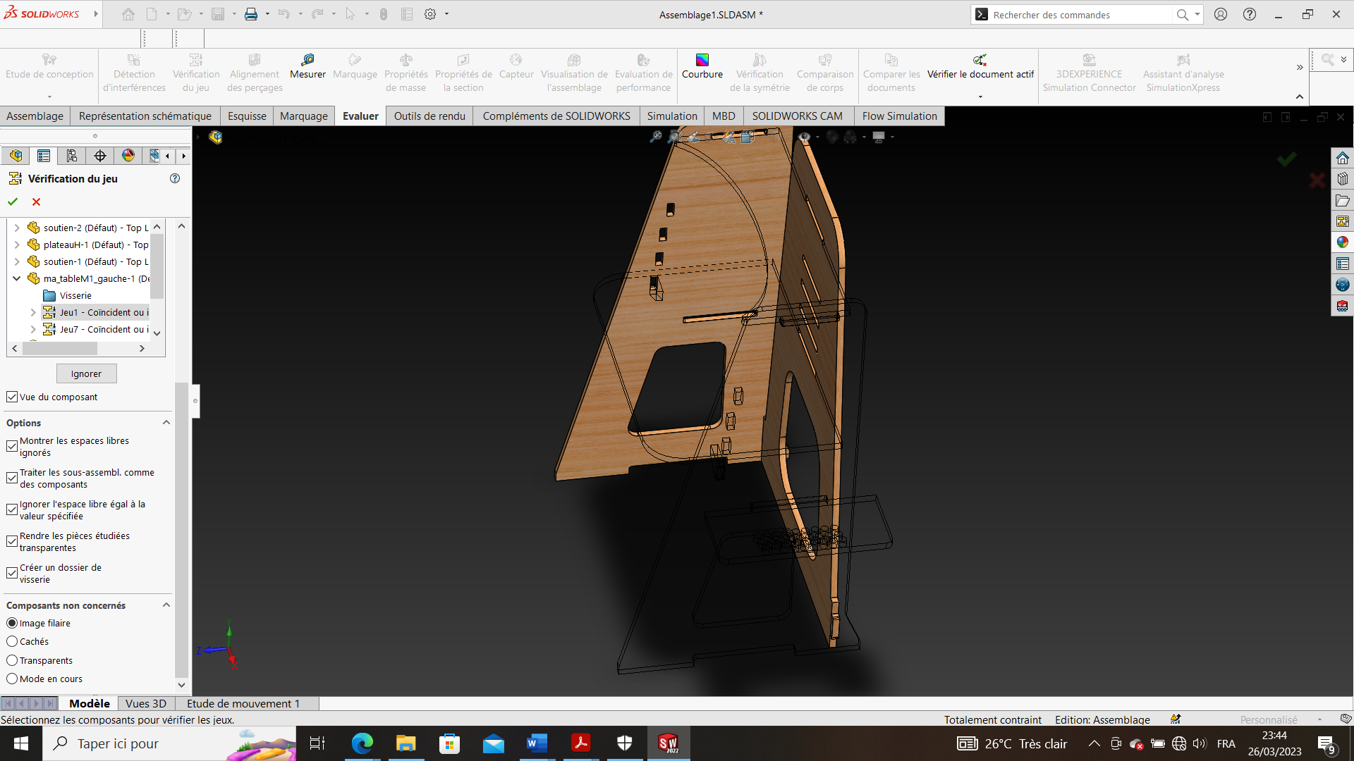
2 assembly.
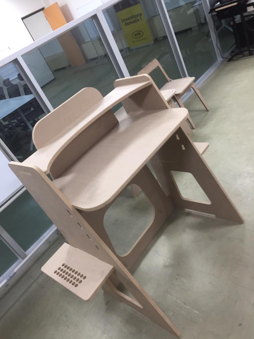
After production this my all parts.
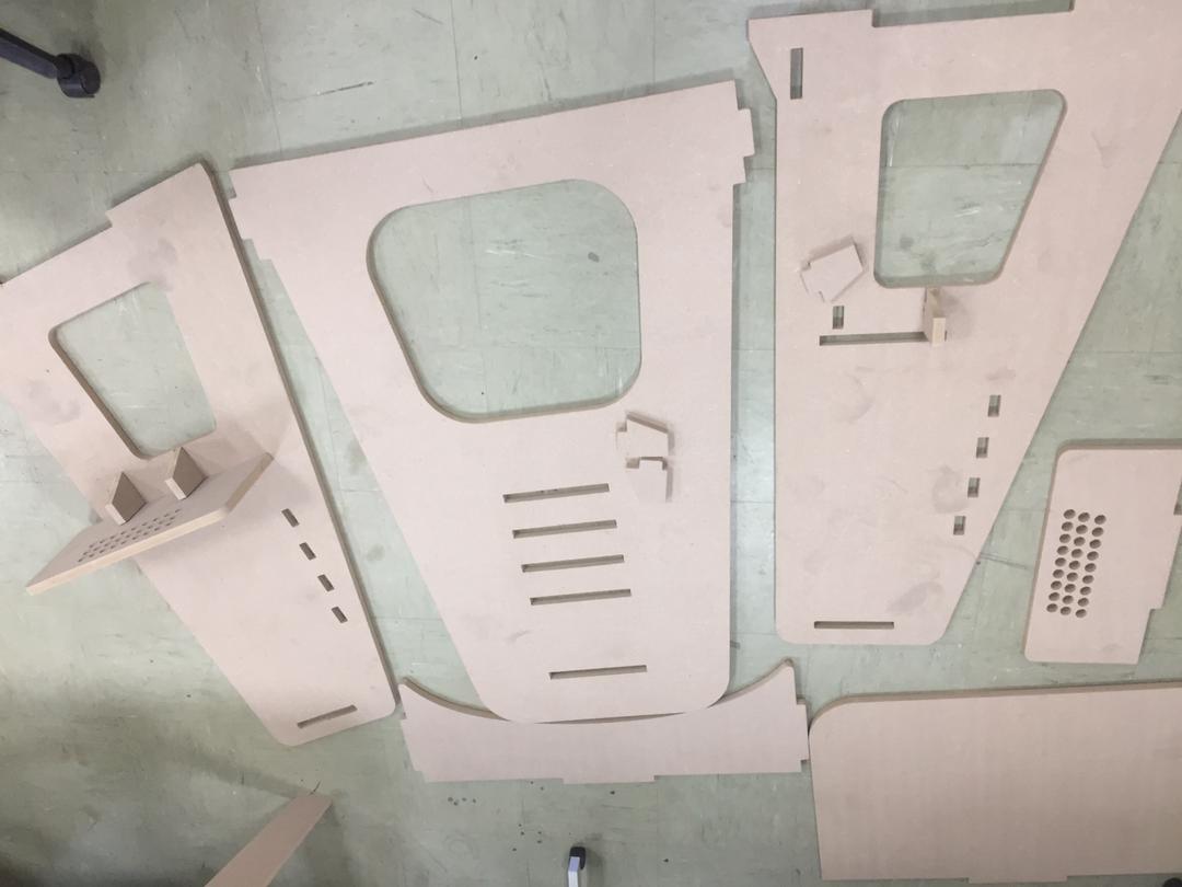
I move to the assembly.
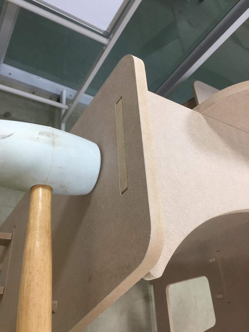
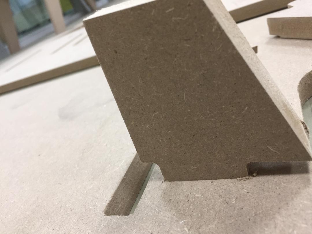
As for assembly, I didn't make any DOG Bones, so it was a bit complicated.
it for that i use hammer to to make it easy.
 .
.
This is how it is presented.
 .
.
 .
.
 .
.
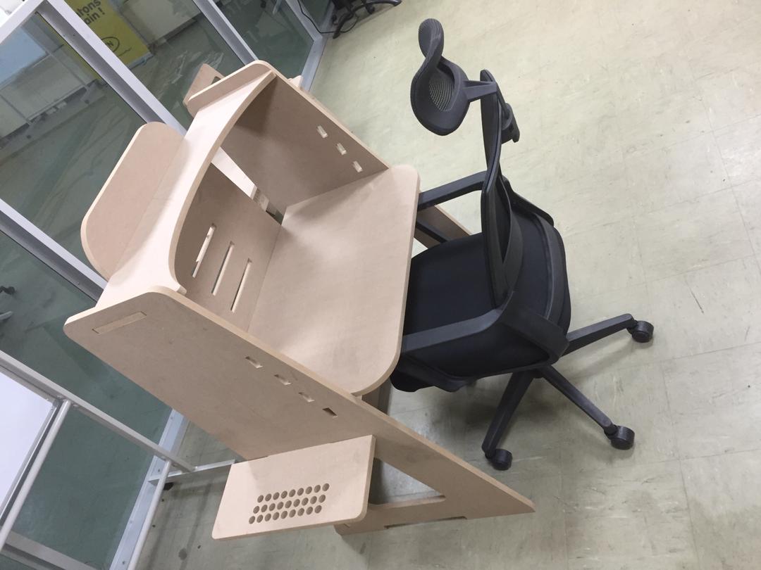
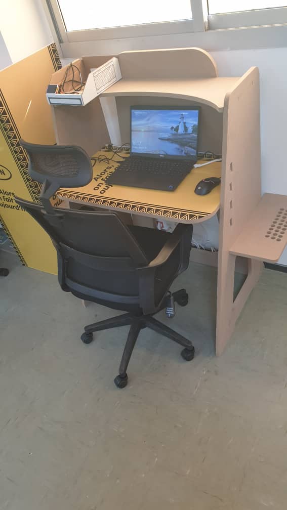
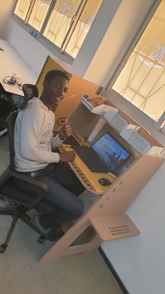
this what my table will going to do
improvement
I redesigned :
- i put the dog bone
 .
.
for the Dog bone i made it as a dimeter of the tool ( End Mil tool 1/8”)
 .
.