5. 3D Scanning and printing
Hero Shots
This week we mainly had to work on the 3D printer and 3D scanning. The main objective being to identify the advantages and limitations of 3D printing and then demonstrate how scanning technology can be used to digitise one or more objects, here is an overview of the assignments.
Assignment Requirements
Group assignment:
- Test the design rules for your printer(s)
- Document your work and explain what are the limits of your printer(s) (in a group or individually)
Individual assignment: - Design and 3D print an object (small, few cm3, limited by printer time) that could not be easily made subtractively - 3D scan an object, try to prepare it for printing (and optionally print it)
Group assignment
THE DEVICE
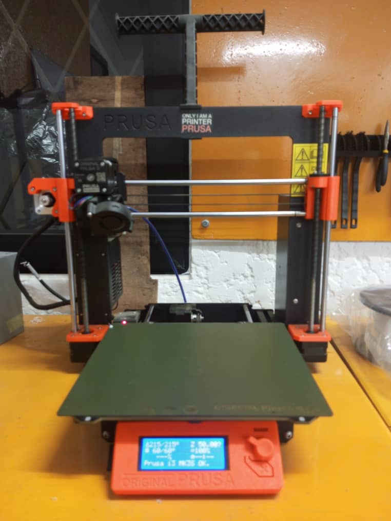
We have at our disposal a Prusa 3D printer model i3 Mk3S. For our group work, we will test the design rules of our printer, explain the limitations of the printer and document our work.
Here is an overview of our printer and its features.
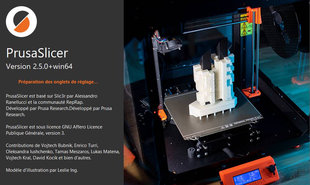
The 3D printer software¶¶
In order for the 3D printer to be able to interpret the 3D files (in .stl format), it will be necessary to use software called a slicer, which will be used to transform the model by slicing/dividing the object into several thin layers superimposed on top of each other, the ones the printer will create. There are several slicer software, but in our case we will use a slicer called PrusaSlicer, which has been developed for Prusa printers.
After we learned how to use the device we began the prints for the group assignment.
3D printer test
In order to characterize and learn the limitations of our machine, we chose to download and print the files that were provided on the Fab Academy assignment page.
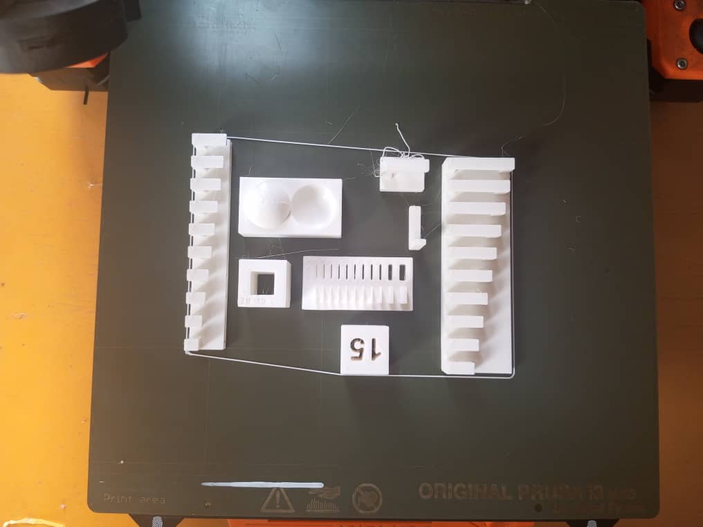
- Overhang and overhang 2
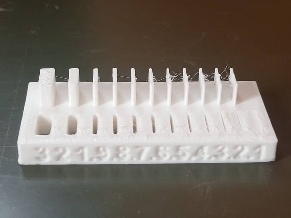
This test looked at how long of an overhang can be used before the print begins to fail. In this test, overhangs of increasing length are printed and the length at which the print becomes messy is the limit. The results for our printer indicated that the limit is approximately 3 mm of overhang
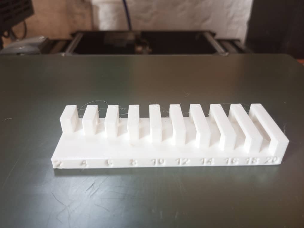
- Bridging
The birdging test evaluates how far your extruder can pul a filament across a gap before drooping or sagging. In this test, the length between two posts is gradually increased. Interestingly, every gap was perfectly bridged
- Wall thickness
In this test, a piece was printed in which wall thicknesses were increased in an additive manner, and the gap between two walls was also printed. The results of this test showed that a minimum thickness of around 0.8mm is required before the wall will not be able to support itself and begin to deform.
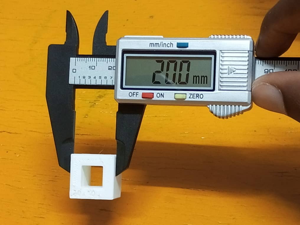
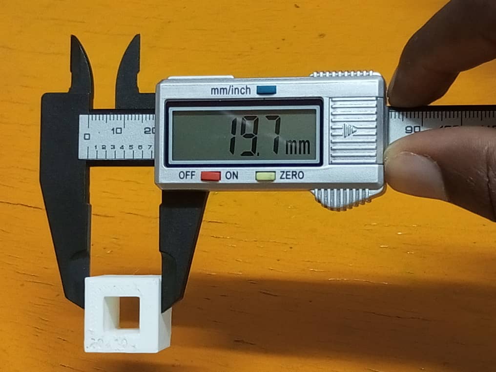
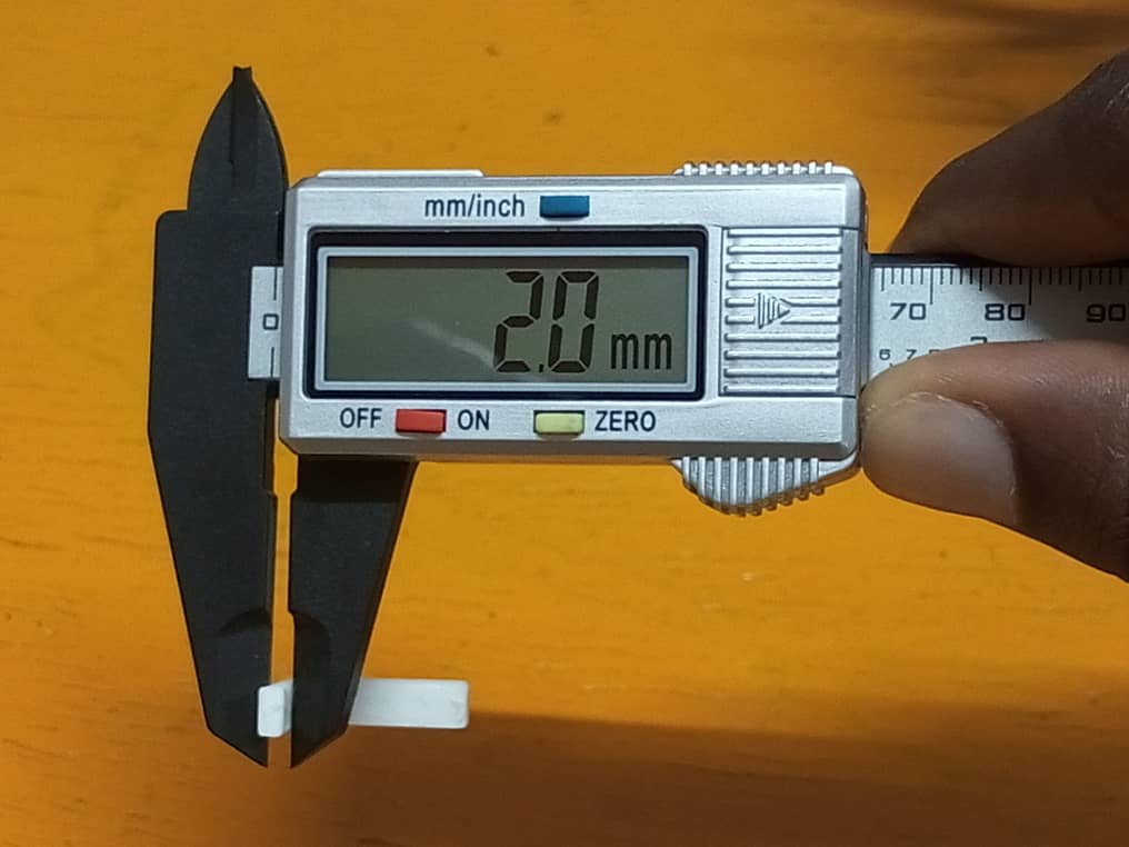
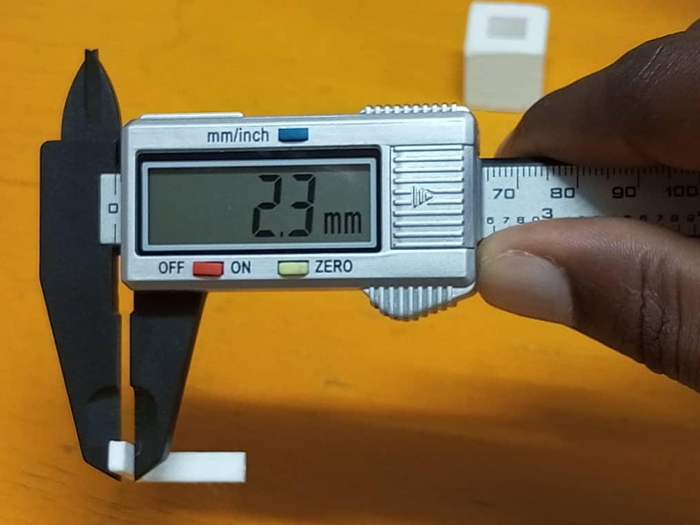
- Dimensions
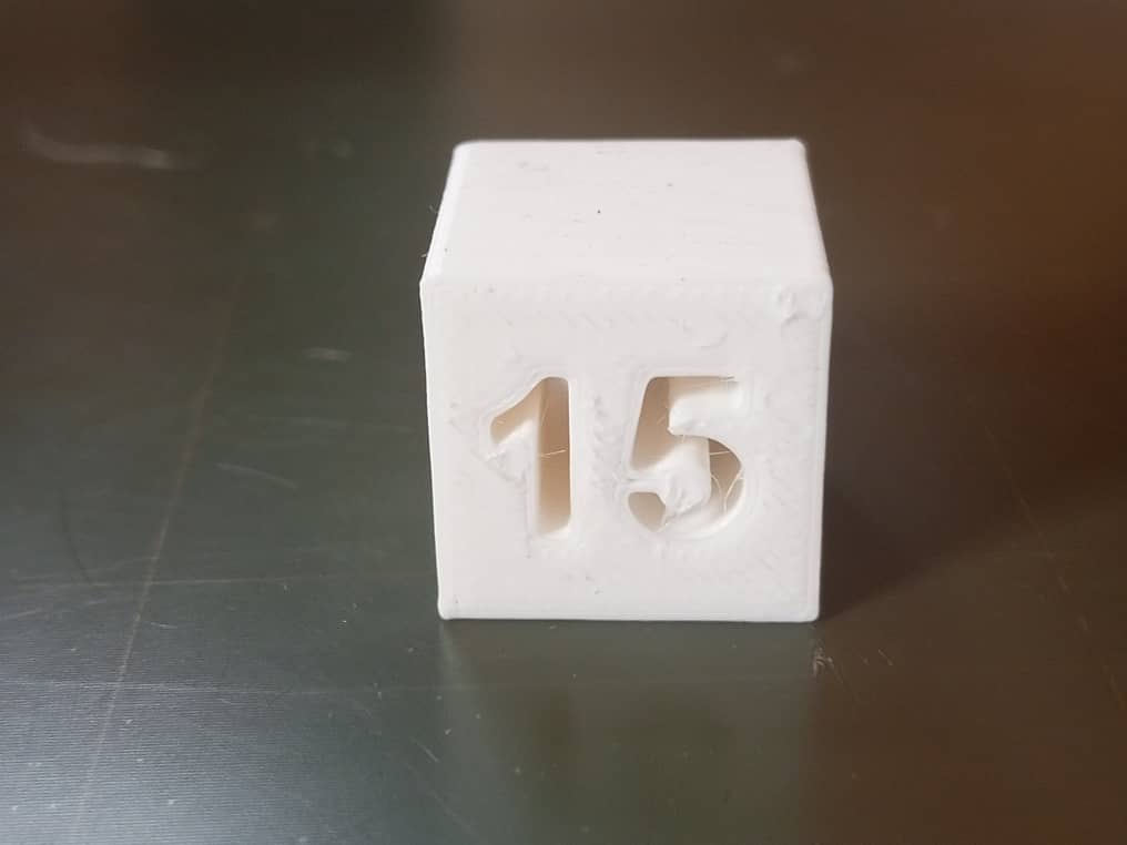
In this print, the accuracy of the dimensions is tested by comparing the printed dimensions as well against the original mesh file dimensions. This will be limited by the width of the extruded filament and the precision of the motors. The test piece had an outer width of 20 mm and an inner width of 10 mm. As demonstrated in the images below, the printer is fairly accurate with a nominally small margin of error.
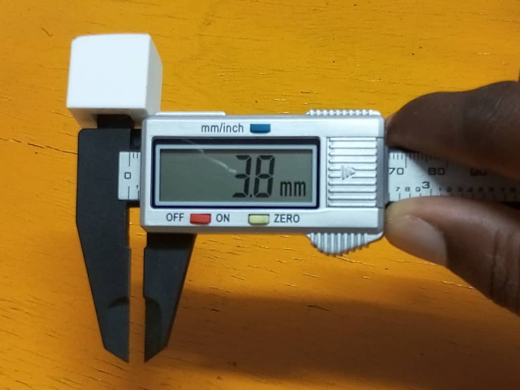
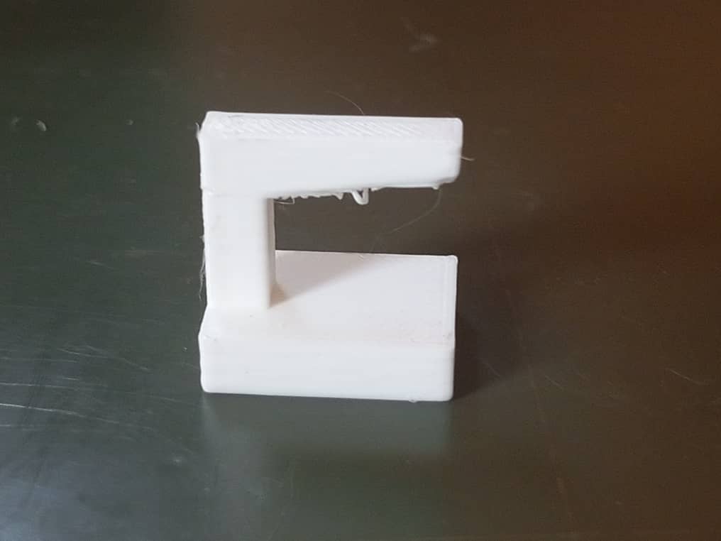
- Anisotropy
In this test the difference between the accuracy of the printer when it is printing horizontally, vs. when it is printing vertically is characterized. This is done by printing a part that is equal in both the horizontal and vertical directions and comparing the actual print dimensions. The results are illustrated in the photos below.
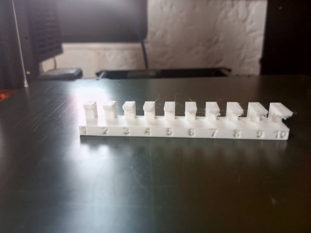
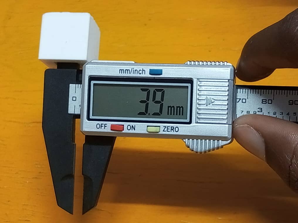
- Surface finish
In this test, we printed a piece that had gradually increasing overhangs to test what angle of departure can be used without supports. The results of the test were that we were able to print to an angle of about 30 degrees before having issues with the print results. The photos below indicate the results of these tests.
Link to group assignment page
The group assignment page can be found on the Energylab 2023 website here
it is also embedded directly in the webpage below.
Individual assignment
3D Scanning
Structured light method
Structured light is a light whose characteristics are known (like a regular grid for example) is projected on the surface to be scanned in 3D. A sensor records the deformation of the light and deduces the shape of the 3D scanned surface.
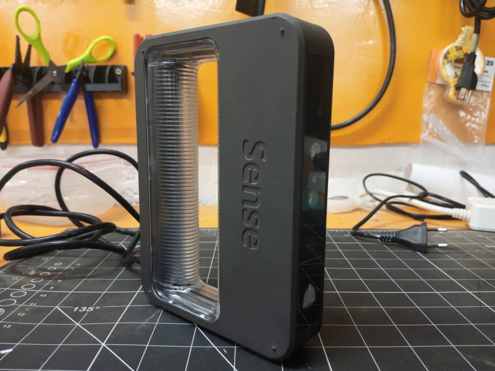
THE DEVICE
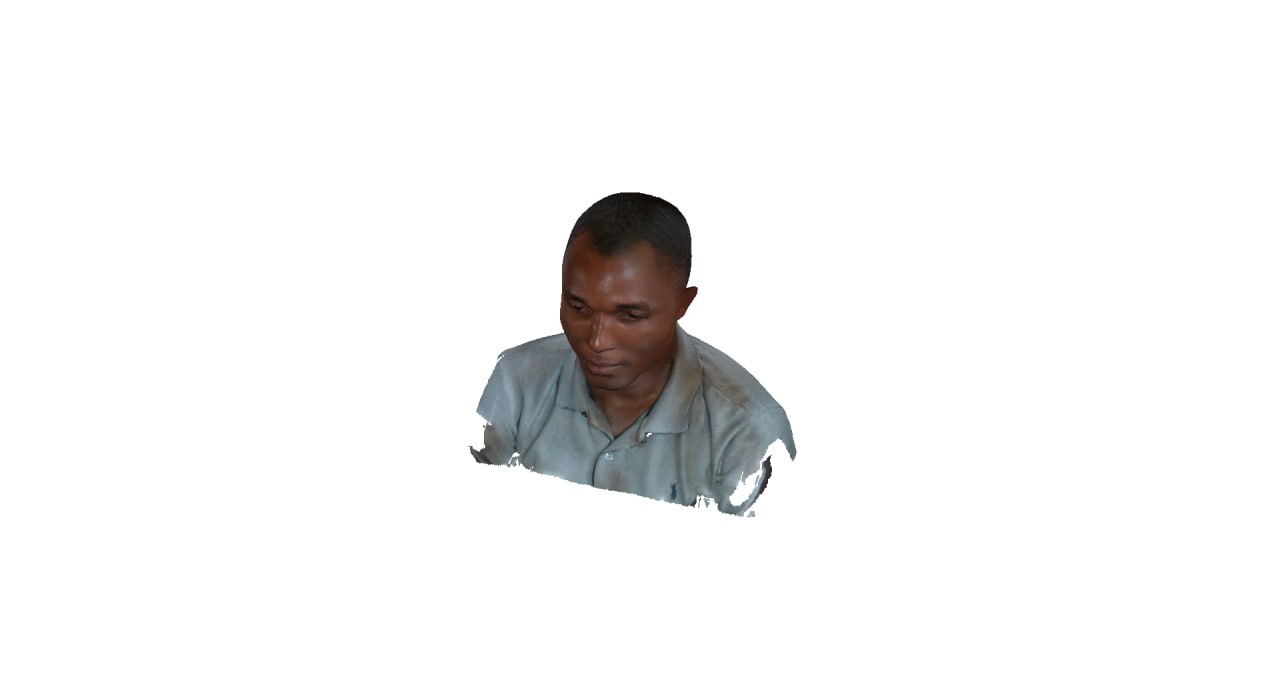
We have used the scanner 3d Sense to apply the method of scanning by structured light.
To perform the scan, we used a software called Sense 3D scanner
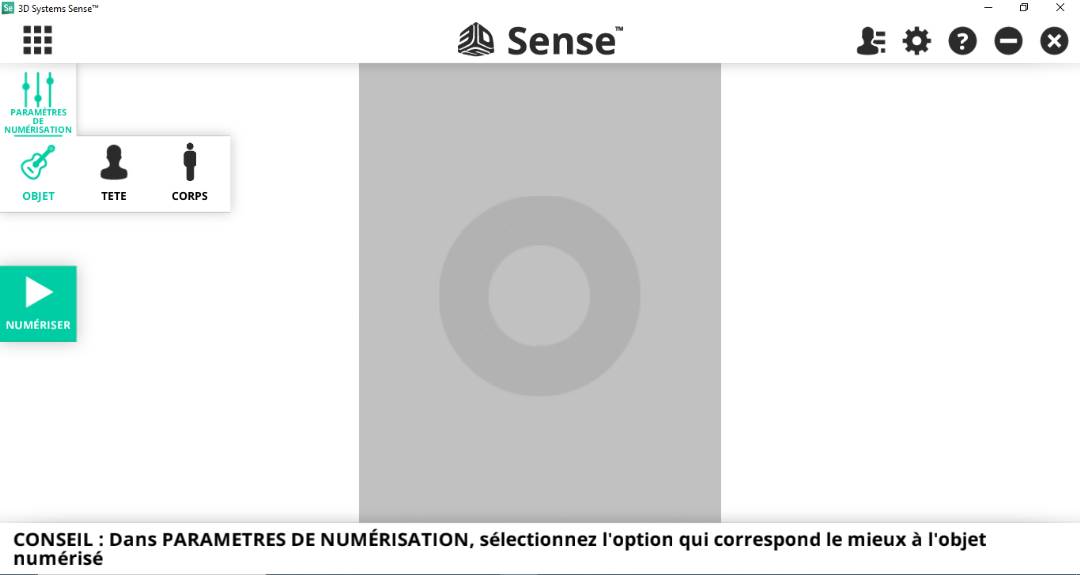
For the scanning process
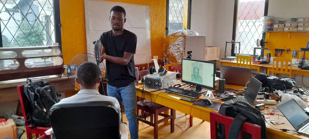
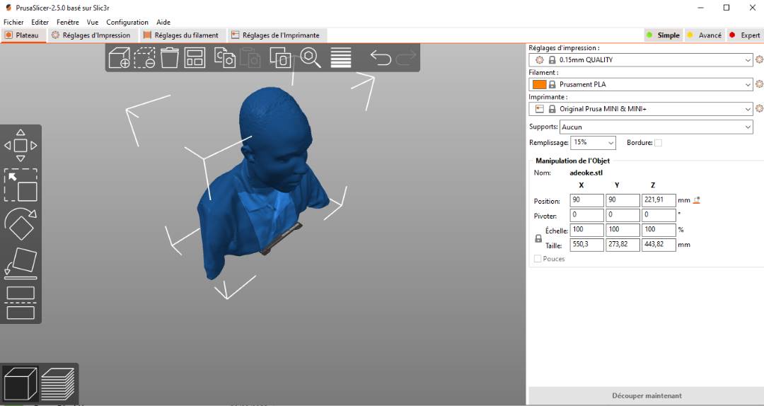
Outcome
Overview of the result in the Prusa software for printing
3D Printing
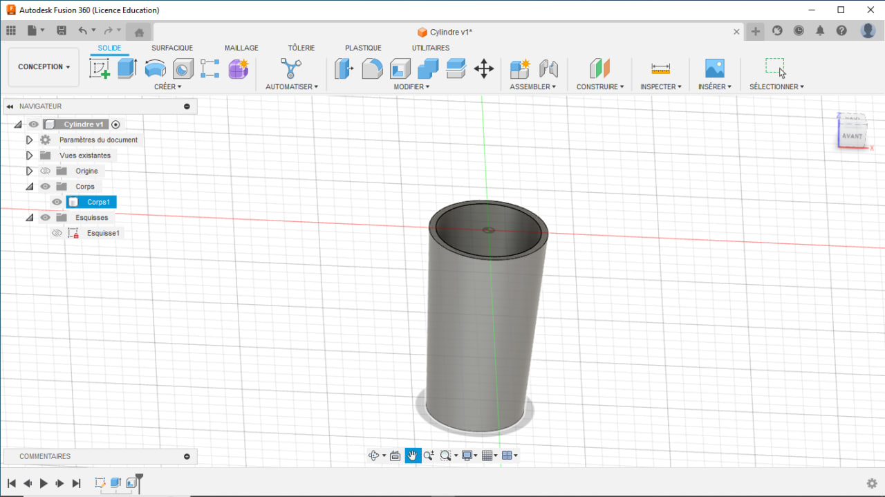
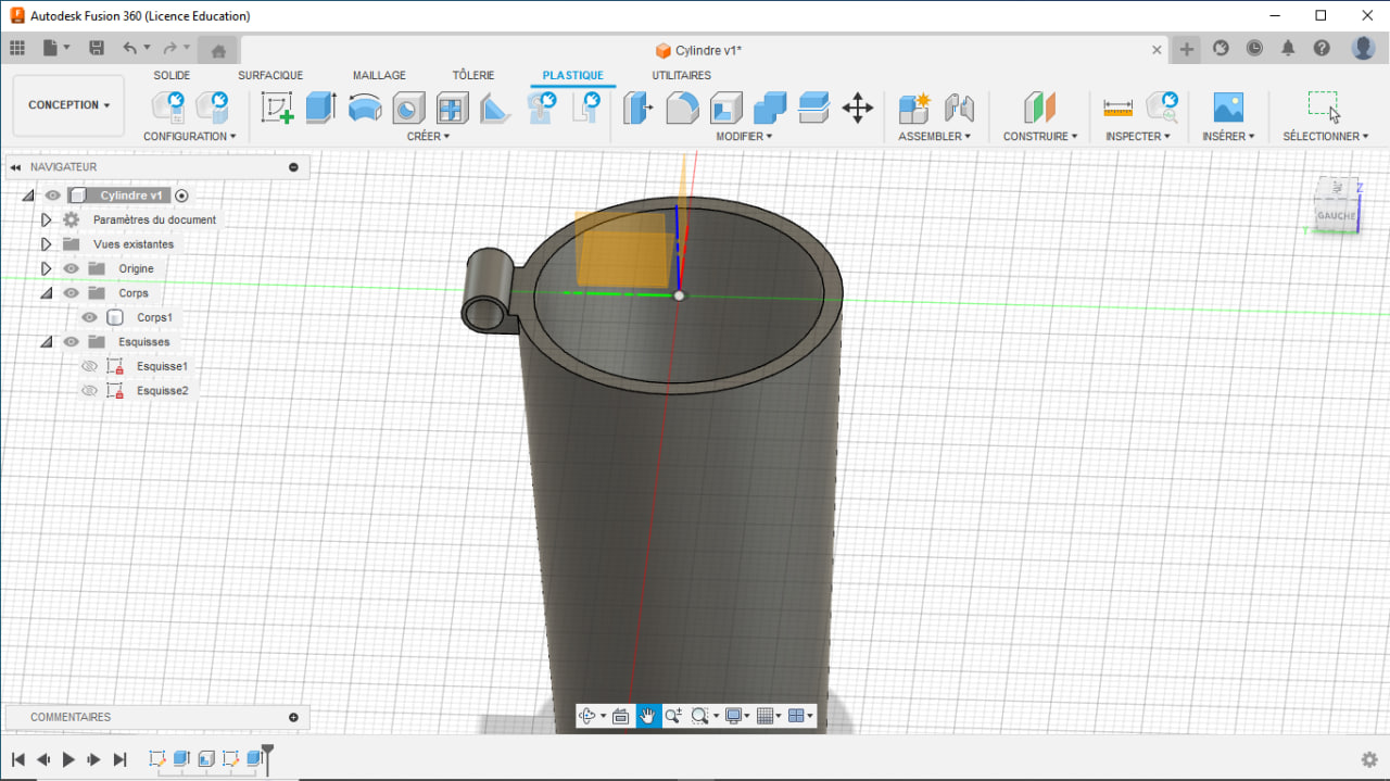
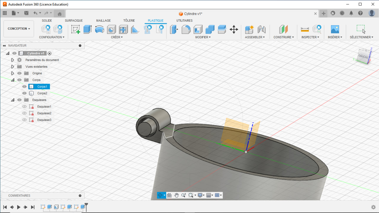
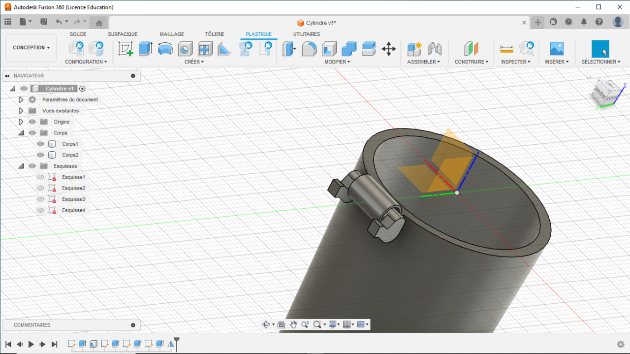
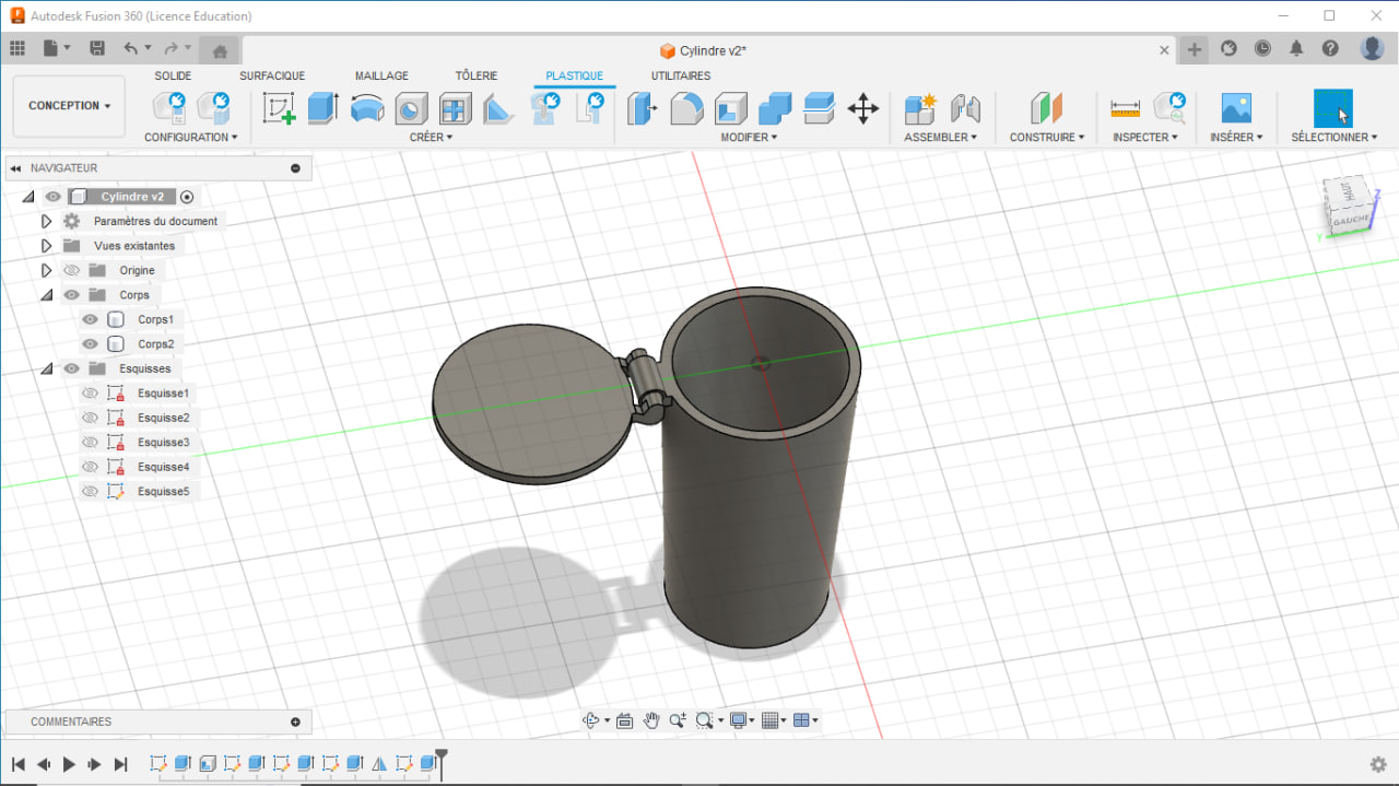
3D Design
I used Fusion 360 for my 3D modelling. You can find more details about it by visiting the work done in Week 2: Computer aided design
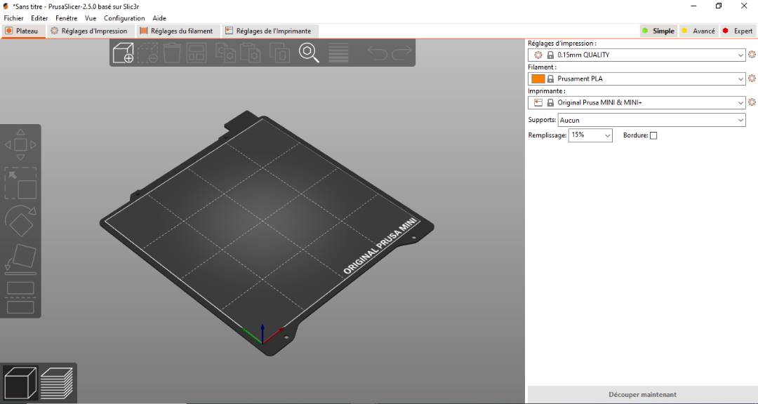
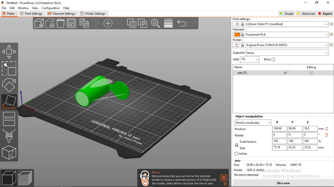
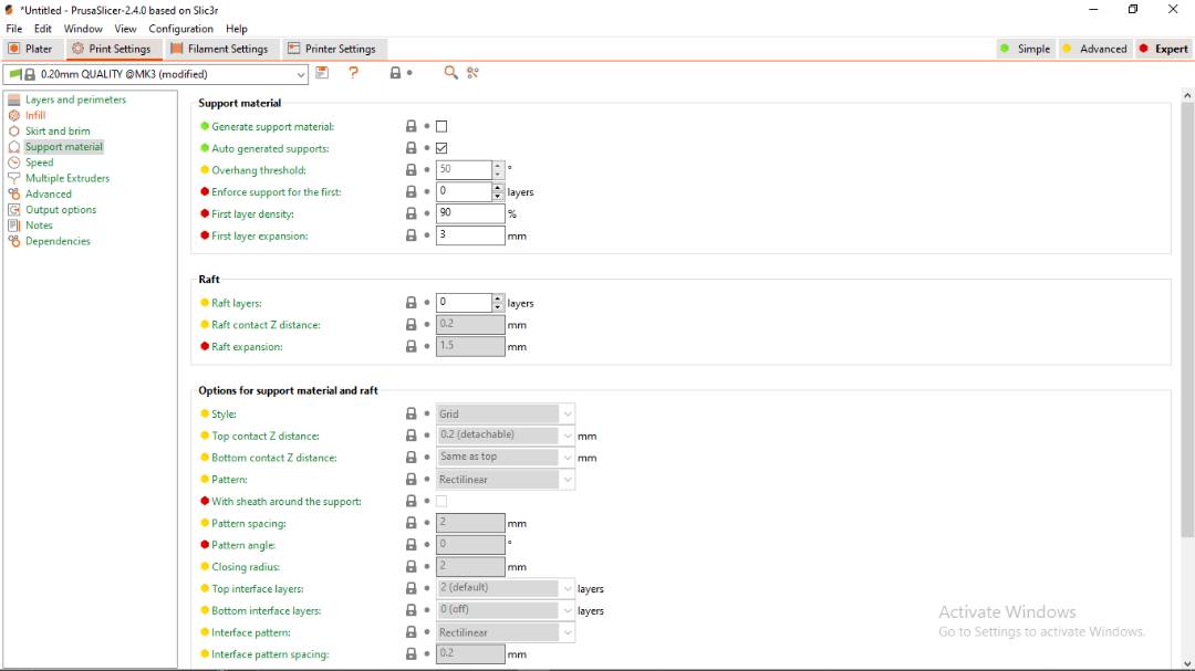
Slicing
First place the item in the Prusa Slicer using the place using face function
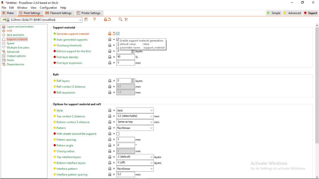
Next we looked at the print settings. Details are included in the screen captures below
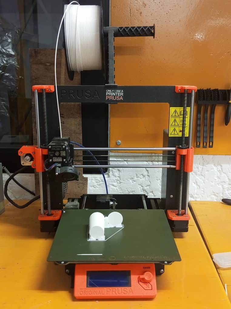
Printing
Next we sliced the file and sent the gcode to an SD card to print on the Prusa printer. You can find the machine details and specifications on the EnergyLab web page here. It is also embedded below:
Below are photos of the machine during printing

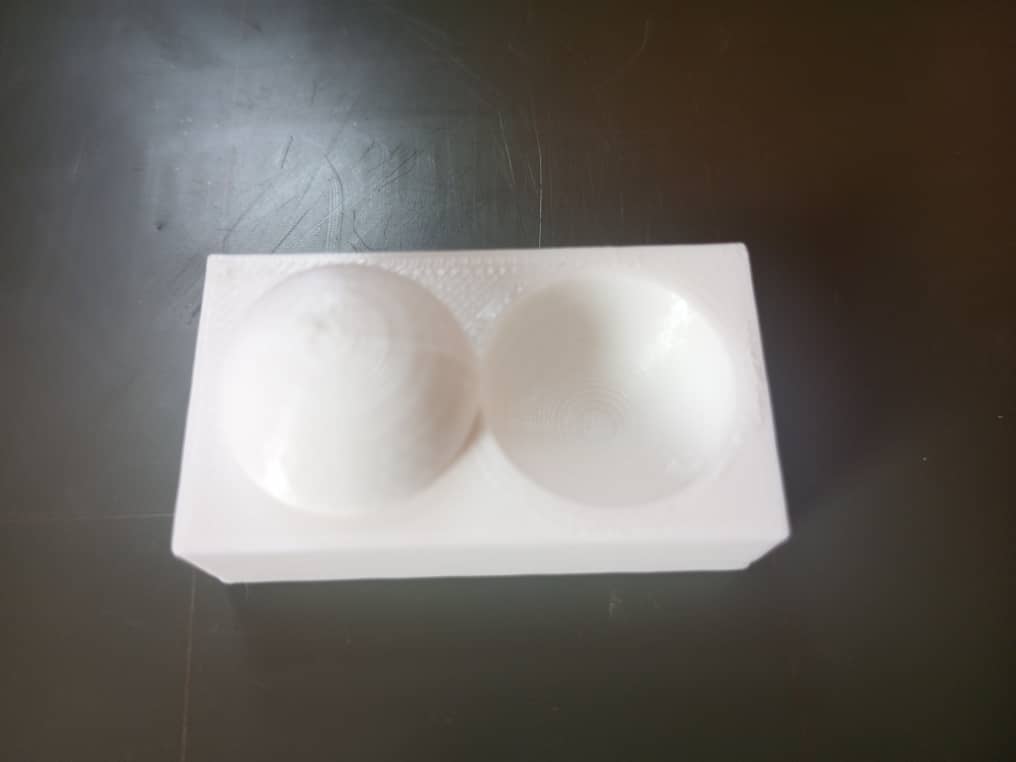
Final Result
Below are photos of the final result
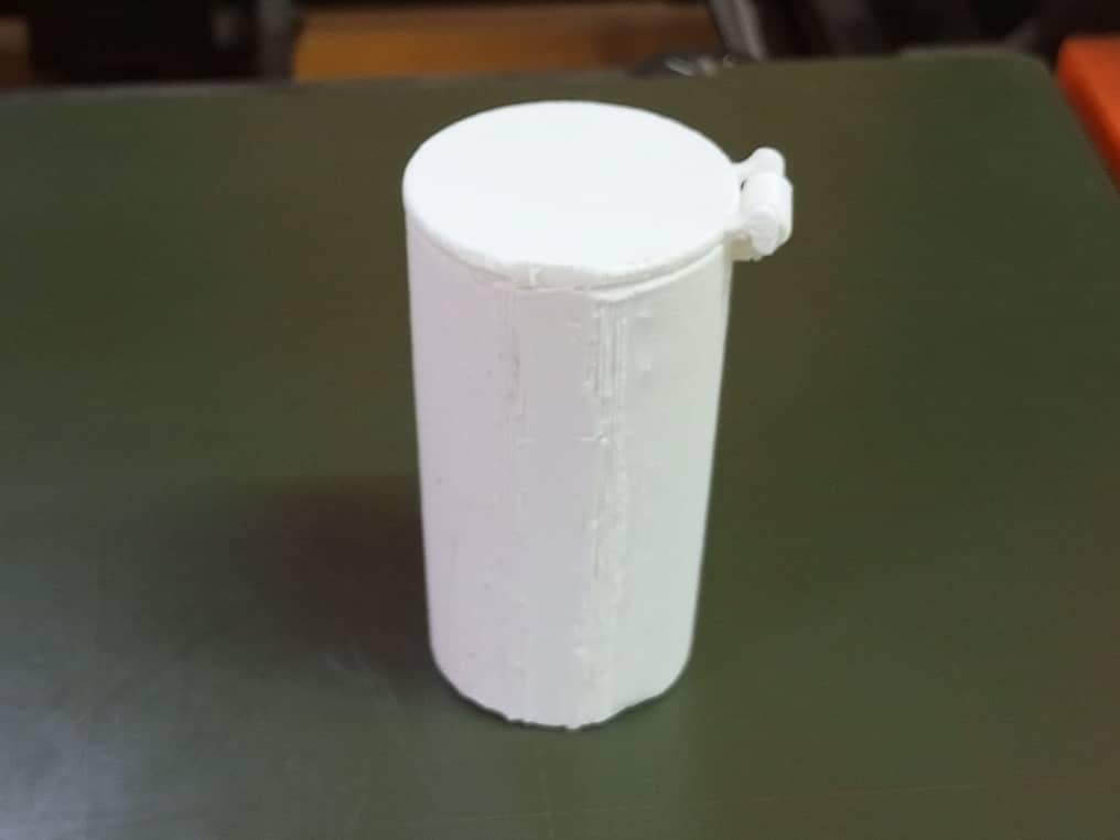
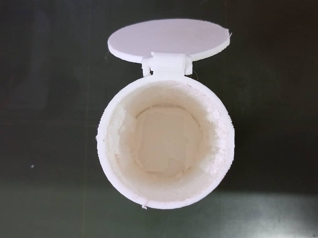
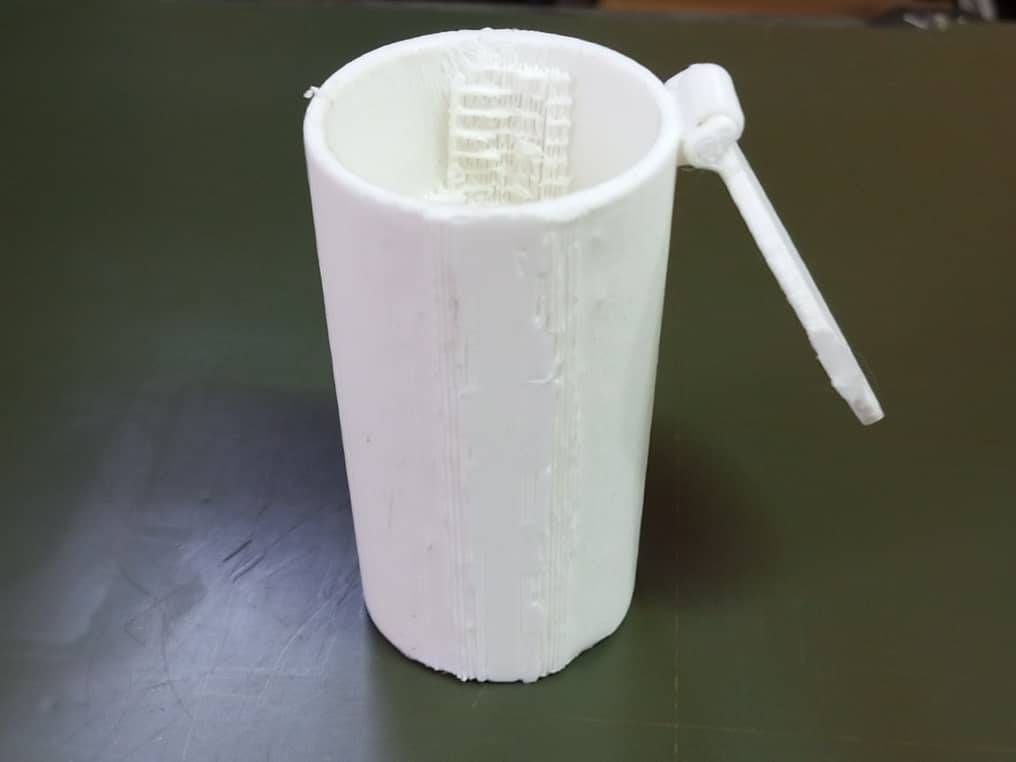
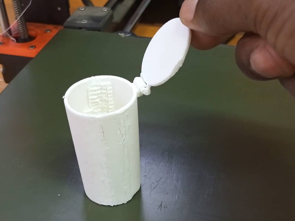
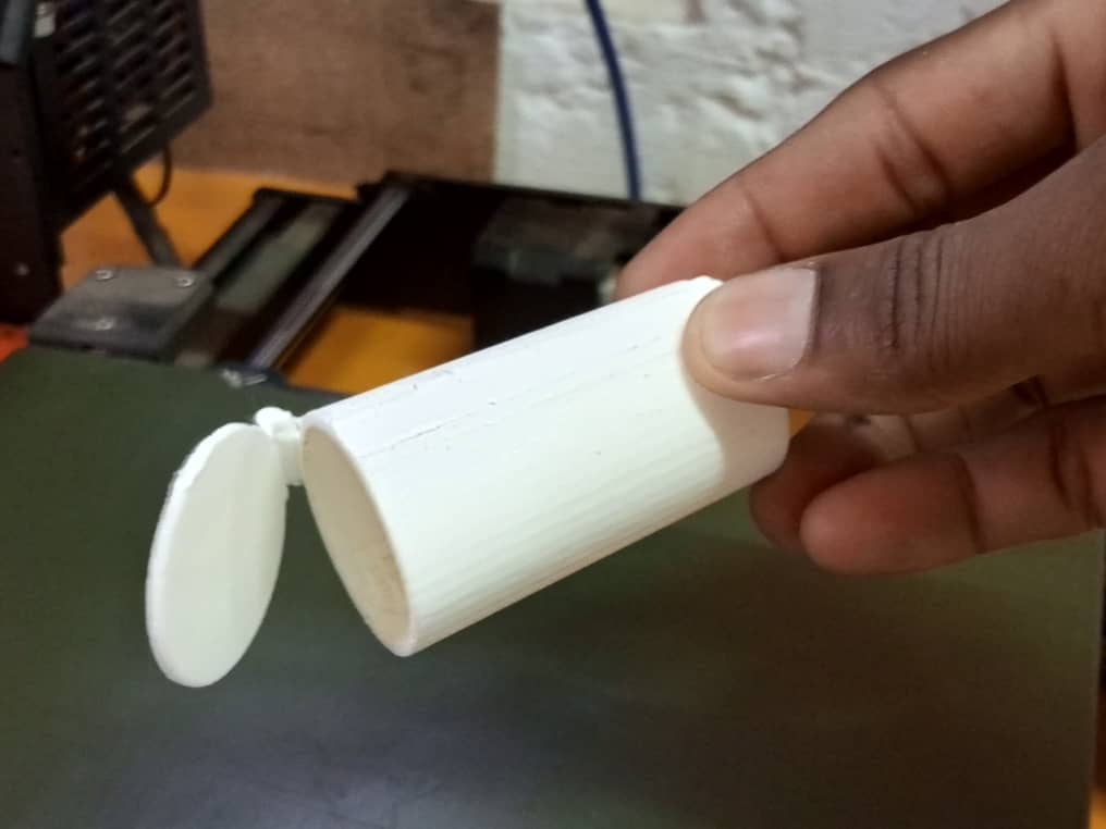
This model cannot be made by subtraction because the geometric shape is complex due to the hinge between the jar and the lid. If you want to manufacture it by subtractive methods, you won’t be able to get the piece in a single block as you did after printing. Instead, we’ll have to assemble several pieces. Quite simply, the subtractive method is not recommended for manufacturing parts with complex geometrical shapes.
What went wrong/what went well
This week, I’d say everything went smoothly, from 3D scanning to printing. Nevertheless, we had a few difficulties with our 3D scan software, which didn’t respond perfectly. But we were able to sort it out so that we could use it and get a better scan. Finally, this is my first time using the 3D scanner and I was very impressed.
Files
Below you can find the original file of my modeling.