4. Embedded Programming
For this fourth week of the course, we had a course on embedded programming.
Assignment Requirements
Individual assignment:
- Browse through the data sheet for your microcontroller
- program a microcontroller development board to interact (with local input &/or output) and communicate (remotely)
- extra credit: use different languages &/or development environments
Group assignment:
Compare the performance and development workflows for other architectures
At EnergyLab, we are 3 students following the fabacademy 2023. For the assignment of this course we have 3 microcontrollers which are:
- ESP 32
- RP 2040
- SAM D21
Each of us had chosen to work on a microcontroller.
For my part, I worked on the SAM D21
Individual assignment:
In my research, I learned that there is a wide range of boards that embed the SAM D microcontroller. Each with different functionality depending on the needs and offer excellent interface and peripheral options with impressive performance at low power consumption. For the purpose of this work, we will focus on the SAM D21. There is also a whole series of the SAM D21 microcontroller that is constantly evolving. We can mention some of them, such as the SAMD21E, SAMD21G, SAMD21J. As I said earlier, in our work we will mainly work on the “Seeed Studio XIAO SAMD21” board. He is the smallest member of the Seeeduino family. It carries the powerful ATSAMD21G18A-MU which is a low-power microcontrollers.
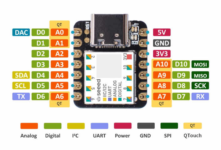
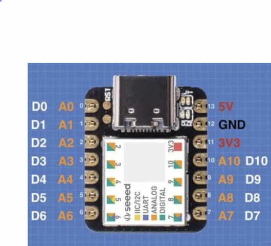
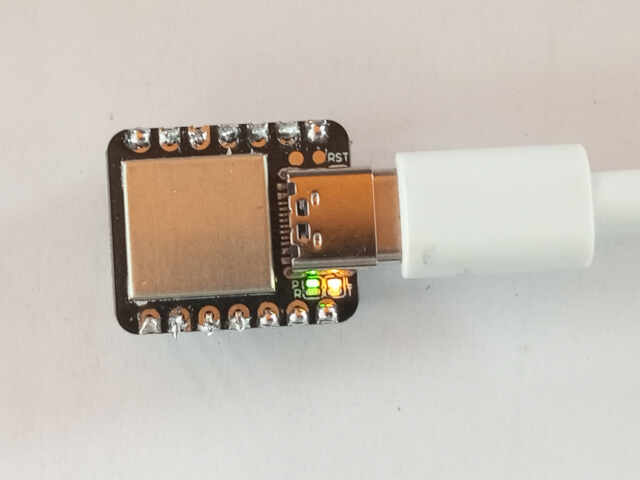
Here are some pictures of Seeed Studio XIAO SAMD21
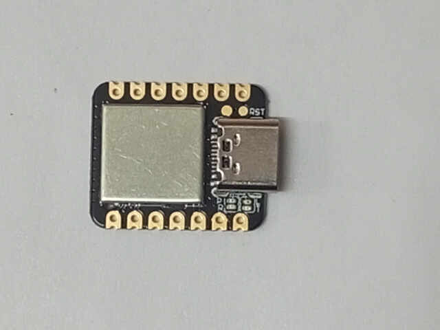
Seeed Studio XIAO SAMD21 has 14 PINs, which can be used for 11 digital interfaces, 11 mock interfaces, 10 PWM interfaces (d1-d10), 1 DAC output pin D0, 1 SWD pad interface, 1 I2C interface, 1 SPI interface, 1 UART interface, Serial communication indicator (T/R), Blink light (L) through pin multiplexing. The colors of LEDs(Power,L,RX,TX) are green, yellow, blue and blue. Moreover, Seeed Studio XIAO SAMD21 has a Type-C interface which can supply power and download code. There are two reset button, you can short connect them to reset the board.
- Top The top of the Seeeduino XIAO has a number of prominent features.
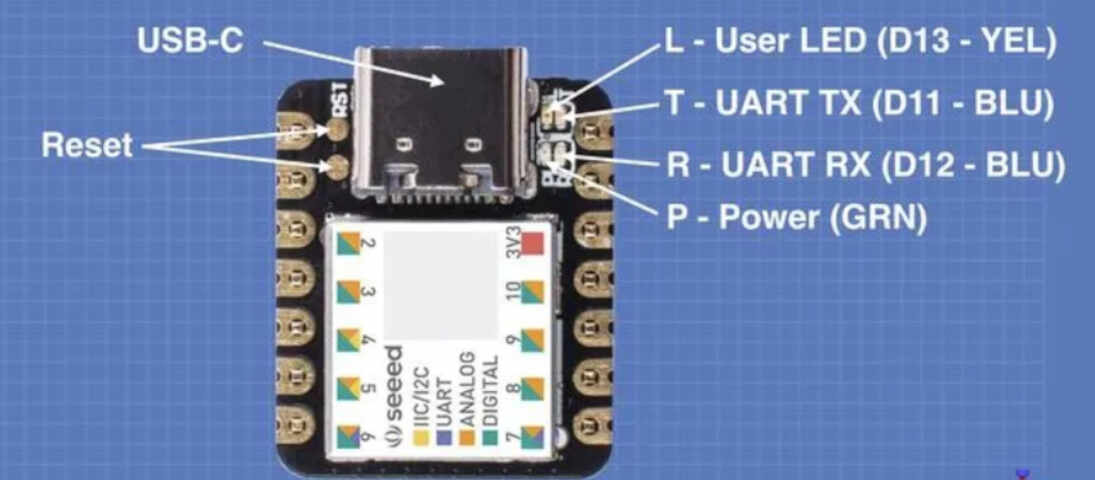
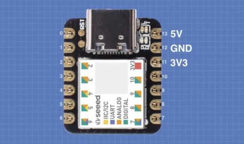
- Power Connections
The ATSAMD21G18 processor is a 3.3-volt device, however, the XIAO has an onboard XC6206P3232MR DC-DC Power Converter to allow the board to be powered by 5-volts as well.
There are actually a few different ways of powering the Seeeduino XIAO:
The USB-C connector powers the XIAO from the attached computer.
You can apply 5-volts to pin 13, this will be reduced to 3.3-volts by the internal DC-DC converter.
You can apply 3.3-volts to pin 11.
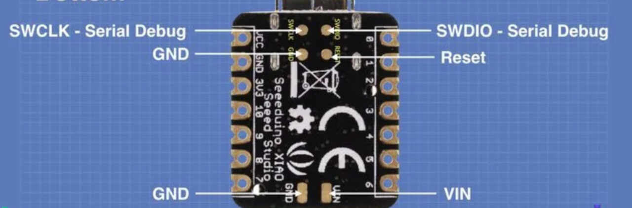
You can use the VCC and GND connections underneath the XIAO and apply 3.7 to 5-volts. This is an ideal method of powering the XIAO with a small LiPo battery.
The power pins can be used as inputs or outputs, as they are attached across the DC-DC converter. If you power the XIAO with the USB-C connection then you can use the power pins as outputs, delivering 5-volts on pin 13 and 3.3-volts on pin 11.
If you apply 5-volts to pin 13 you can use pin 11 as a 3.3-volt output. You can also power the XIAO by providing your own 3.3-volt power supply and connecting it to pin 11 – in this case the 5-volt pin is non-functional.
Pin 12 is the Ground connection.
- Analog Input Connections
He has 11 analog inputs, each connected to a 12-bit A/D converter.
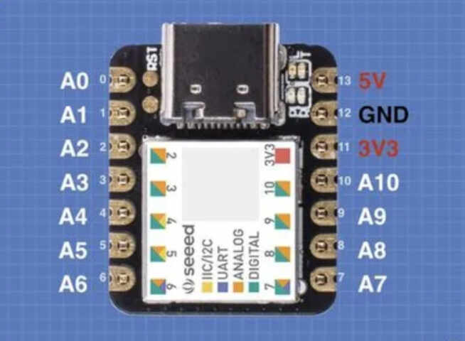
- Digital I/O Connections
The XIAO also has 11 digital I/O pins, sharing the same pins as the analog inputs.
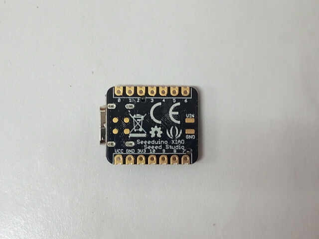
- Bottom
The underside of the Seeeduino XIAO also has a few extra pads for additional connections.
IDE for XIAO programming
Now that we have seen the hardware connections to the XIAO it’s time to learn how to program it. There are actually two ways to do this:
- Using C++ and the Arduino IDE. It is also possible to use Platform IO.
- Using CircuitPython, a Python subset enhanced for microcontrollers. For this assignment we will focus on using the Arduino IDE, and after will explore other methods for programming the XIAO.
Setting up the Arduino IDE for the Seeeduino XIAO
Before we can use our Arduino IDE with the XIAO we will need to install another board manager. Actually, there are two steps you’ll need to take – installing the new Board Manager and installing the XIAO board itself. Here is how to accomplish this.
1 – Install the Seeeduino SAMD21 Boards Manager
Seeed Studio has a board manager that works with the XIAO and with many other Seeeduino products. It can be installed as follows: Open the Arduino IDE. Click the File menu, and then click Preferences. The Preferences window will open. Locate the Additional Boards Manager URLs textbox, near the bottom of the Preferences window.
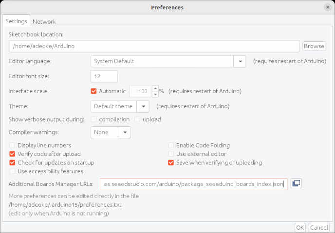
You’ll need to insert the following URL into the Additional Boards Manager URLs textbox:
- If the Additional Boards Manager URLs textbox is empty then simply paste the above URL into the textbox.
- If the Additional Boards Manager URLs textbox already has an entry then click on the button to the right of the textbox. This will open up a dialog box which will allow you to add additional board managers. Paste the above link into this box, below the other entry or entries. Click the modal boxes OK button when done.
Now wen can click the OK button to accept the new entry and close the Preferences window. And we are now ready for the next step.
2 – Install the XIAO Board
Now that the new Boards Manager has been installed into your Arduino IDE you can perform the final step – installing the Seeeduino XIAO board itself.
- Open the Arduino IDE
- Open the Tools item from the top menu and select Boards Manager.
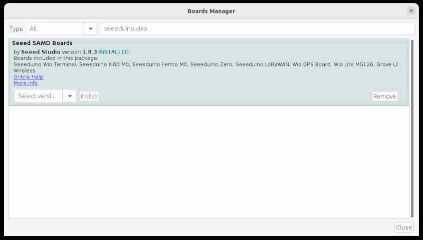
- The Boards Manager window will open.
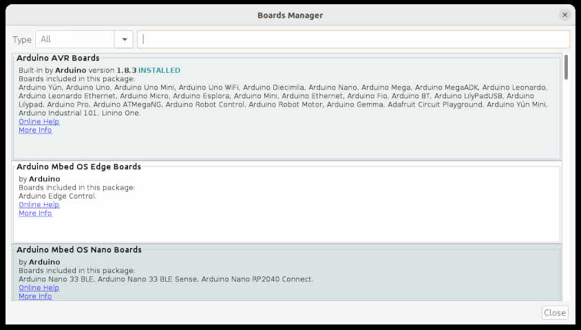
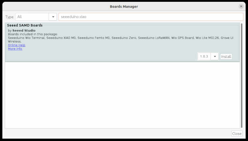
- In the filter textbox type “seeeduino xiao”
- The Seeed SAMD Boards package will be displayed
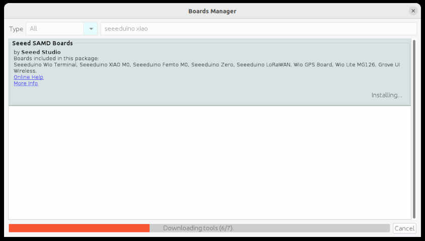
- Click the Install button to install the package. Be patient, as it can take a while!
- Click the Close button when you are done.
Once you have done this you should now be able to select Seeeduino XIAO from the list of Seeed SAMD Boards.
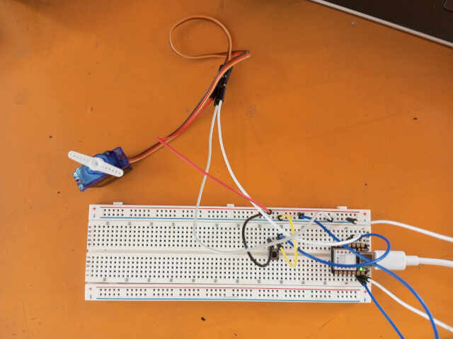
To test my board, I decided to control a servomotor (which I could use in my final project if necessary), perhaps using a pushbutton through the microcontroller.
-
Here’s a preview of the code
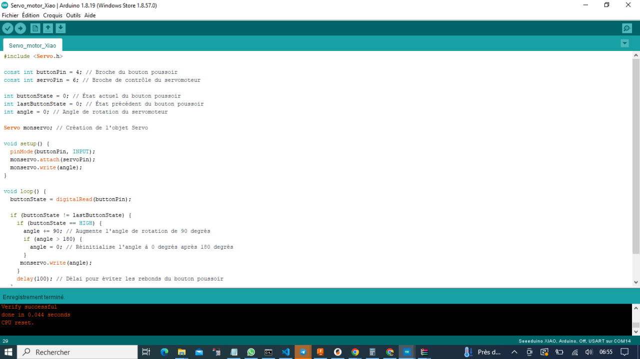
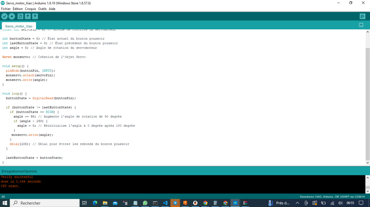
-
Here is the code in detail
#include <Servo.h>
This line includes the Servo library, which is necessary for controlling the servo motor.
const int buttonPin = 4 ; // Button pin
const int servoPin = 6; // Servo control pin
These lines define the pin numbers for the button and the servo motor.
int buttonState = 0; // Current button state
int lastButtonState = 0; // Previous button state
int angle = 0; // Servo rotation angle
These lines declare variables to store the current state of the button (buttonState), the previous state of the button (lastButtonState), and the angle of rotation for the servo motor (angle).
Servo monservo; // Servo object
This line creates a Servo object named monservo. This object will be used to control the servo motor.
void setup() {
  pinMode(buttonPin, INPUT);
  monservo.attach(servoPin);
  monservo.write(angle);
}
The setup() function is executed once at the start of the program. It sets the button pin as an input using pinMode(), attaches the servo motor to the specified pin using attach(), and initializes the servo motor’s position to the initial angle using write().
void loop() {
  buttonState = digitalRead(buttonPin);

  if (buttonState != lastButtonState) {
    if (buttonState == HIGH) {
      angle += 90; // Increase rotation angle by 90 degrees
      if (angle > 180) {
        angle = 0; // Reset angle to 0 degrees after 180 degrees
      }
      monservo.write(angle);
    }
    delay(100); // Delay to debounce the button
  }

  lastButtonState = buttonState;
}
The loop() function is executed repeatedly as long as the Arduino board is powered on. During each iteration of the loop, it reads the current state of the button using digitalRead() and compares it to the previous state.
If the button is pressed (HIGH state), it increments the rotation angle of the servo motor by 90 degrees using angle += 90. If the angle exceeds 180 degrees, it resets the angle to 0 degrees.
Then, it updates the position of the servo motor by using monservo.write(angle), which rotates the servo motor to the specified angle.
Finally, a delay of 100 milliseconds is added using delay(50) to debounce the button.
- Assembly images
Group assignment
Concerning the group assignment of this week, it’s about comparing different maps to highlight the different features.
To do this, I made the comparison between my XIAO SAMD 21 card and those used by my colleagues, namely ESP-32 and RP2040.
Below, here is the comparison table.
| Item | Seeed Studio XIAO ESP32C3 | Seeeduino XIAO mine | Seeed XIAO RP2040 |
|---|---|---|---|
| Processor | ESP32-C3 32-bit RISC-V @160MHz | SAMD21 M0+@48MHz | RP2040 Dual-core M0+@133Mhz |
| Wireless Connectivity | WiFi and Bluetooth 5 (LE) | N/A | N/A |
| Memory | 400KB SRAM, 4MB onboard Flash | 32KB SRAM 256KB FLASH | 264KB SRAM 2MB onboard Flash |
| Built-in Sensors | N/A | N/A | N/A |
| Interfaces | I2C/UART/SPI/I2S | I2C/UART/SPI | I2C/UART/SPI |
| PWM/Analog Pins | 11/4 | 11/11 | 11/4 |
| Onboard Buttons | Reset/ Boot Button | N/A | Reset/ Boot Button |
| Onboard LEDs | Charge LED | N/A | Full-color RGB/ 3-in-one LED |
| Battery Charge Chip | Built-in | N/A | N/A |
| Programming Languages | Arduino | Arduino/ CircuitPython | Arduino/ MicroPython/ CircuitPython |
You can also find this comparison on the website of our fablab by clicking here .