09. Output devices
Hero Shots
Assignent Requirements
Group assignment
-
Measure the power consumption of an output device.
-
Document your work on the group work page and reflect on your individual page what you learned.
Individual assignment
Add an output device to a microcontroller board you’ve designed and program it to do something.
Group Assignment
Requirements:
-
Measure the power consumption of an output device.
-
Document your work on the group work page and reflect on your individual page what you learned.
Link to group assignment page
The group assignment page can be found on the Energylab 2023 website here
it is also embedded directly in the webpage below.
-
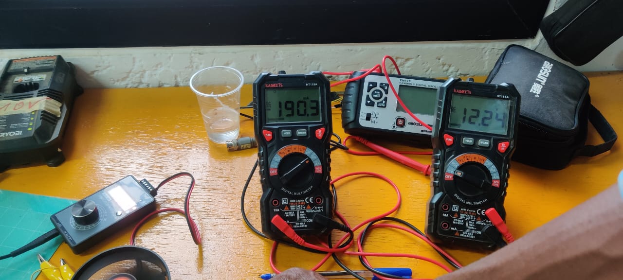
As you can see from the pictures, we were measuring the voltage and current flowing in our circuit, consisting of a DC ±10V / 0-22 mA power supply and a small fan. This is one of the components in my colleague’s project.
-
To measure the voltage at the terminals of our fan, we placed the voltmeter in parallel with it, and to measure the current, we placed the amperemeter in series with the circuit.
-
On the picture we can see that the voltage is 12.24 V and the current 190.3 mA.
-
This means that for our little fan to work properly, it needs to be supplied with a DC voltage of around 12.24 V and a DC current of around 190.3 mA.
Individual assignment
Requirements:
Add an output device to a microcontroller board you’ve designed and program it to do something.
Here’s what I did to complete the individual task of adding an output device to a microcontroller and programming it to perform a specific task:
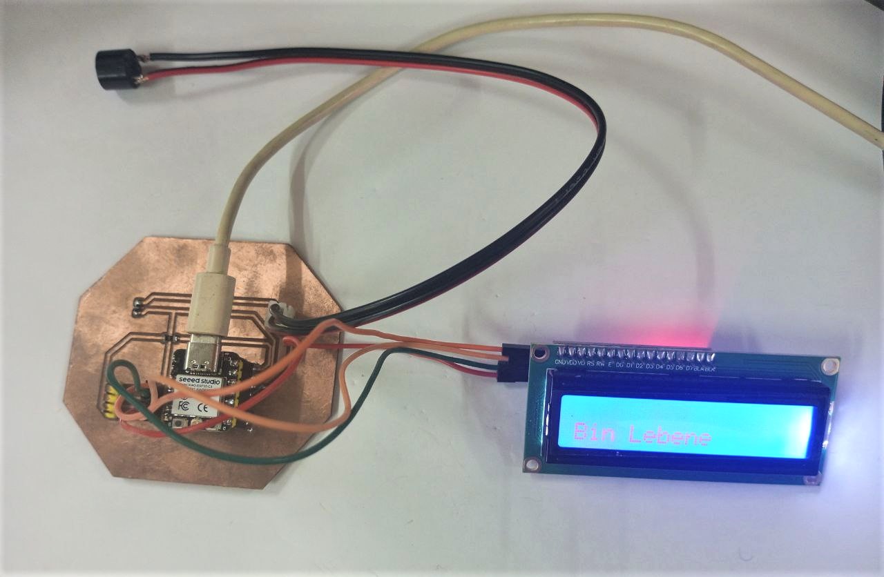
I used an LCD screen and a buzzer as output devices, then a XIAO ESP32C3 microcontroller to control them.
- LCD screen
Description
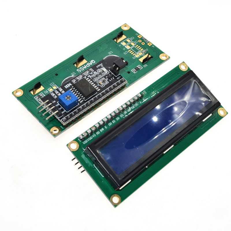
This is an electronic device used for displaying data and messages. It’s known as a 16x2 LCD because it has 16 columns and 2 rows, so it can display a total of 32 characters (16 × 2 = 32). The color of the characters is white, and the screen has a blue background. This also makes it readable in the dark.
Specification
| Features | Value |
|---|---|
| Brand | DSD TECH |
| Model | SH-D1602 |
| Operating voltage | 5 V |
| Screen resolution | 2 lines x 16 characters |
| Character resolution | 5 x 8 pixels |
| Module dimensions | 80 x 36 x 12 mm |
| Display of zone dimensions | 64.5 x 16.4 mm |
Connection
Connect the VCC pin of the LCD screen to the 5V power supply (VCC) of the XIAO ESP32C3.
Then connect the GND pin of the LCD screen to the ground pin (GND) of the XIAO ESP32C3.
Then connect the SDA pin of the LCD screen to SDA pin on the XIAO SAMD21.
Finally, connect the SCL pin of the LCD screen to SCL pin on the XIAO SAMD21.
- Buzzer
Description
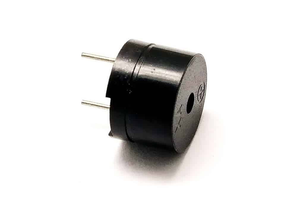
This is a kind of low-power loudspeaker which, depending on the frequency and amplitude of vibration, emits a sound. It can be used to play notes and recreate simple melodies.
Specification
| Features | Value |
|---|---|
| Brand | FTVOGUE |
| Model | FTVOGUEpo195t37ag |
| Sound pressure level | 85 to 95 decibels |
| Nominal voltage | 12VDC |
| Working voltage range | 3V-24V |
| Maximum current | 10mA |
Operating principle
When an electric current is applied to the buzzer pins, the piezoelectric crystal vibrates mechanically at a specific frequency. This vibration creates sound waves that propagate through the air, producing an audible sound.
Connection
Connect the VCC pin of the buzzer to the 5V power supply (VCC) of the XIAO ESP32C3.
Then connect the GND pin of the buzzer to the ground pin (GND) of the XIAO ESP32C3.
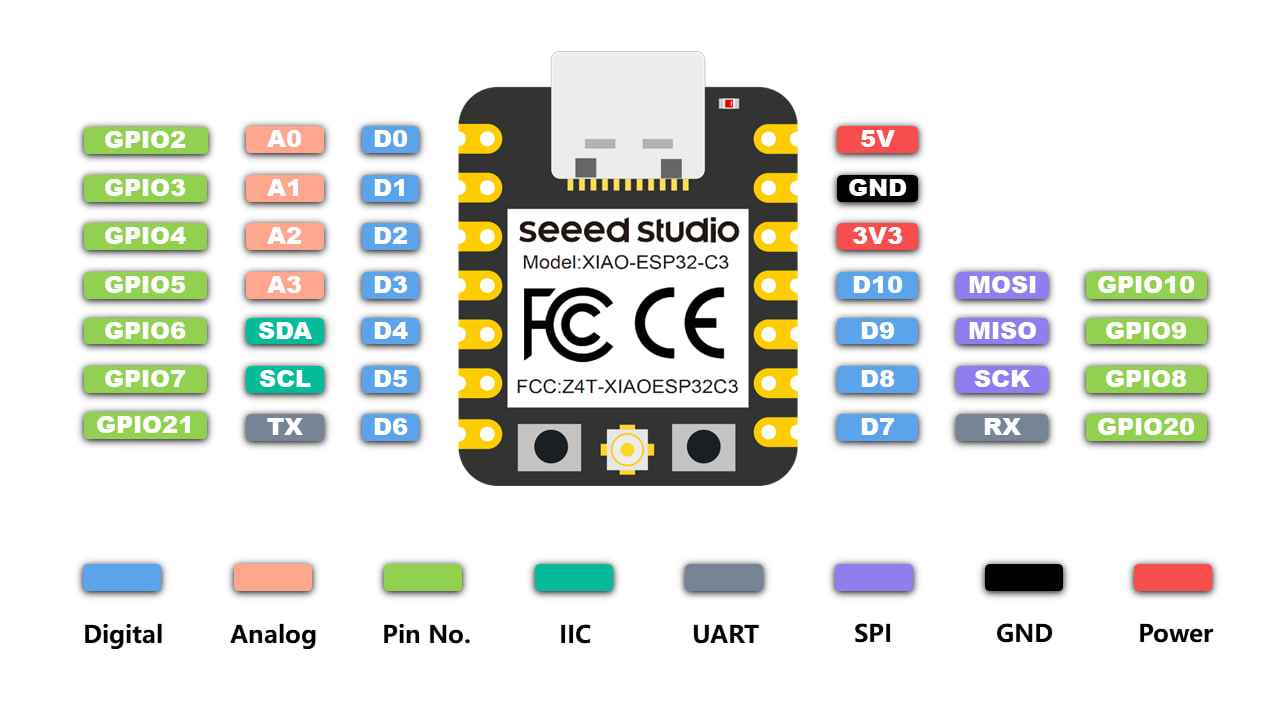
- XIAO ESP32C3
As for my board, I carried out the design in week 6 (Electronics design) and the production and soldering of the pins in week 8 (Electronics production).
Here are the different steps I took to build my board:
To start with the design, I did some research to identify the different pins and functionalities of my microcontroller.
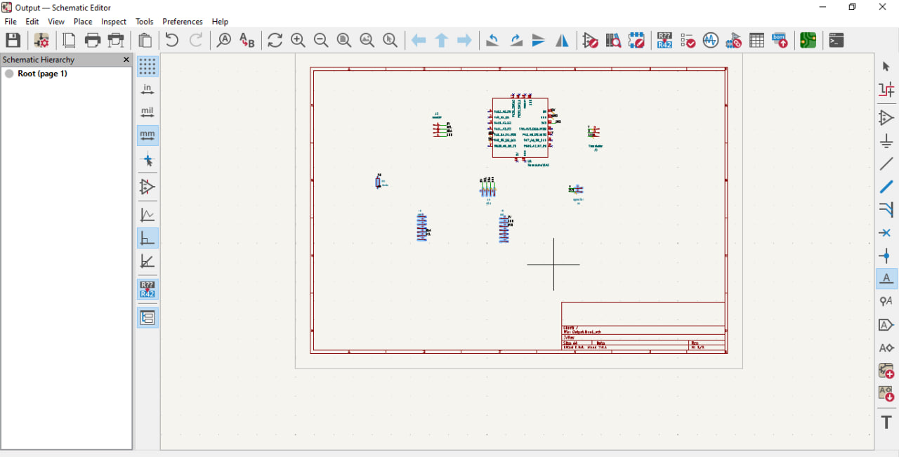
- After that, I started by creating a schematic of my board in KICAD.
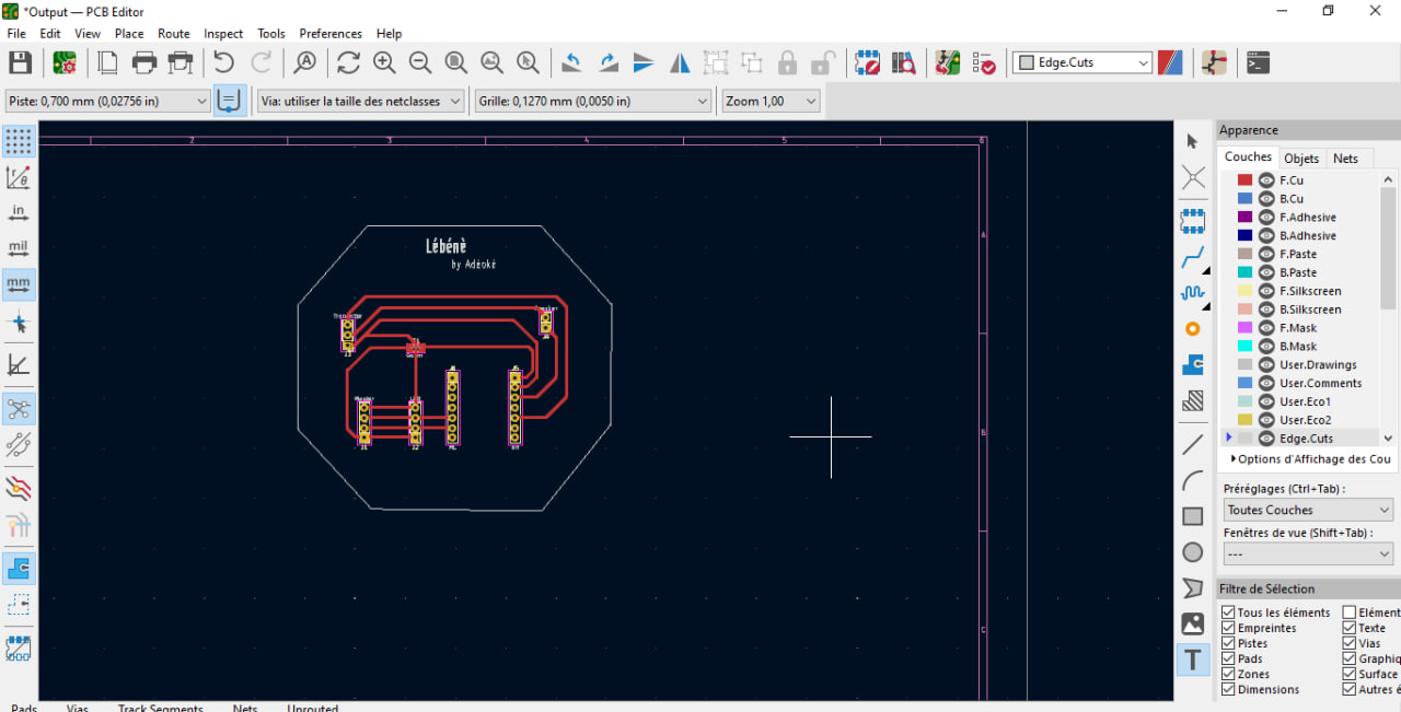
- After the schematic, I moved on to making the PCB, again in KICAD.
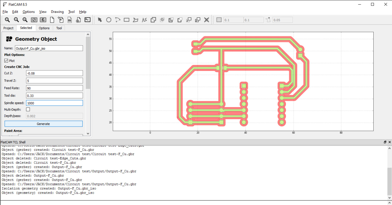
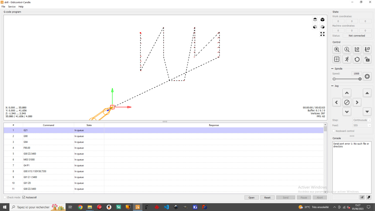
- Then I switched to Flatcam to generate the Gcode.
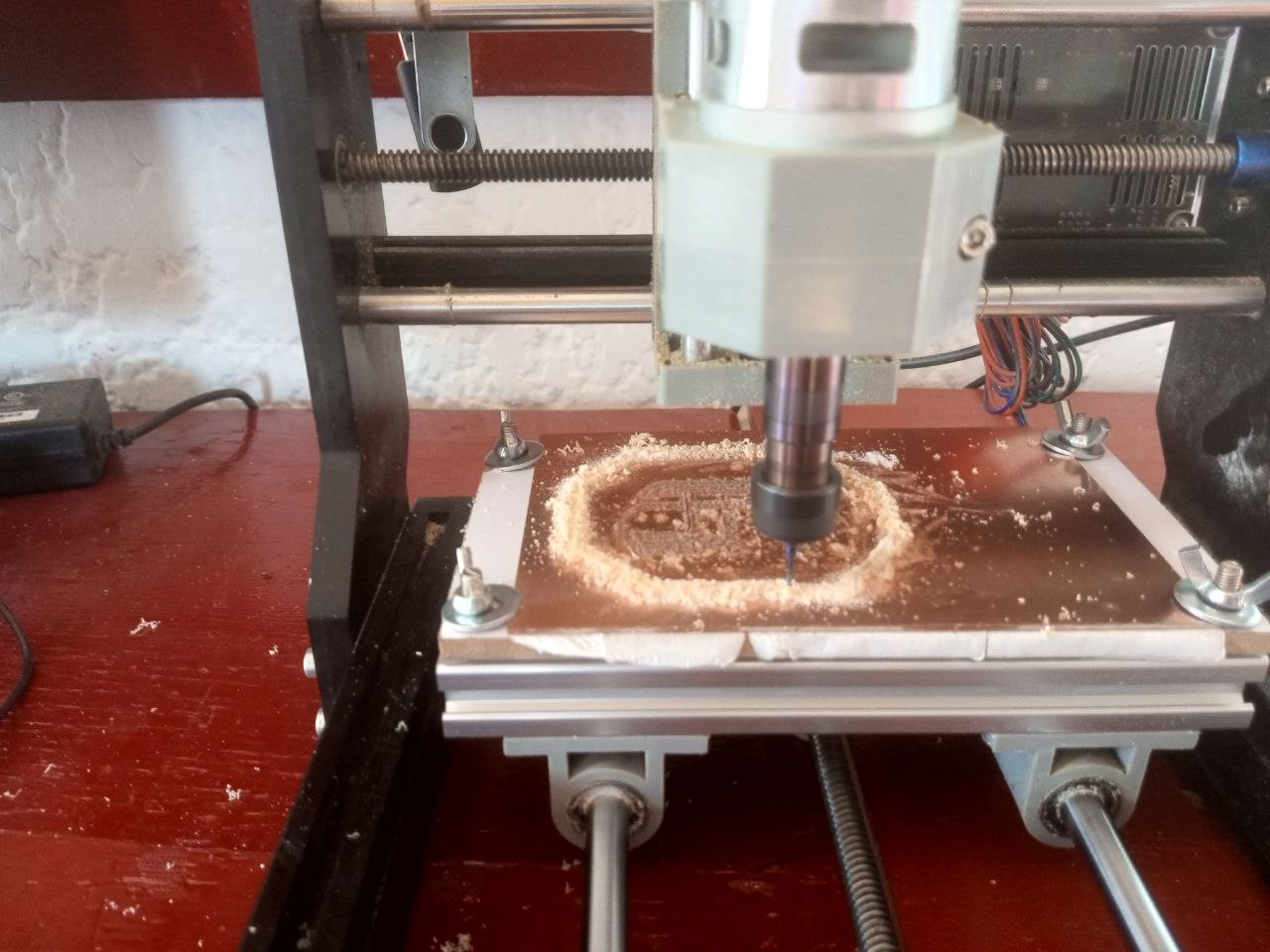
- After generating the Gcode, let’s move on to milling
Now that we’ve got our board, let’s move on to soldering the various pins on the board.
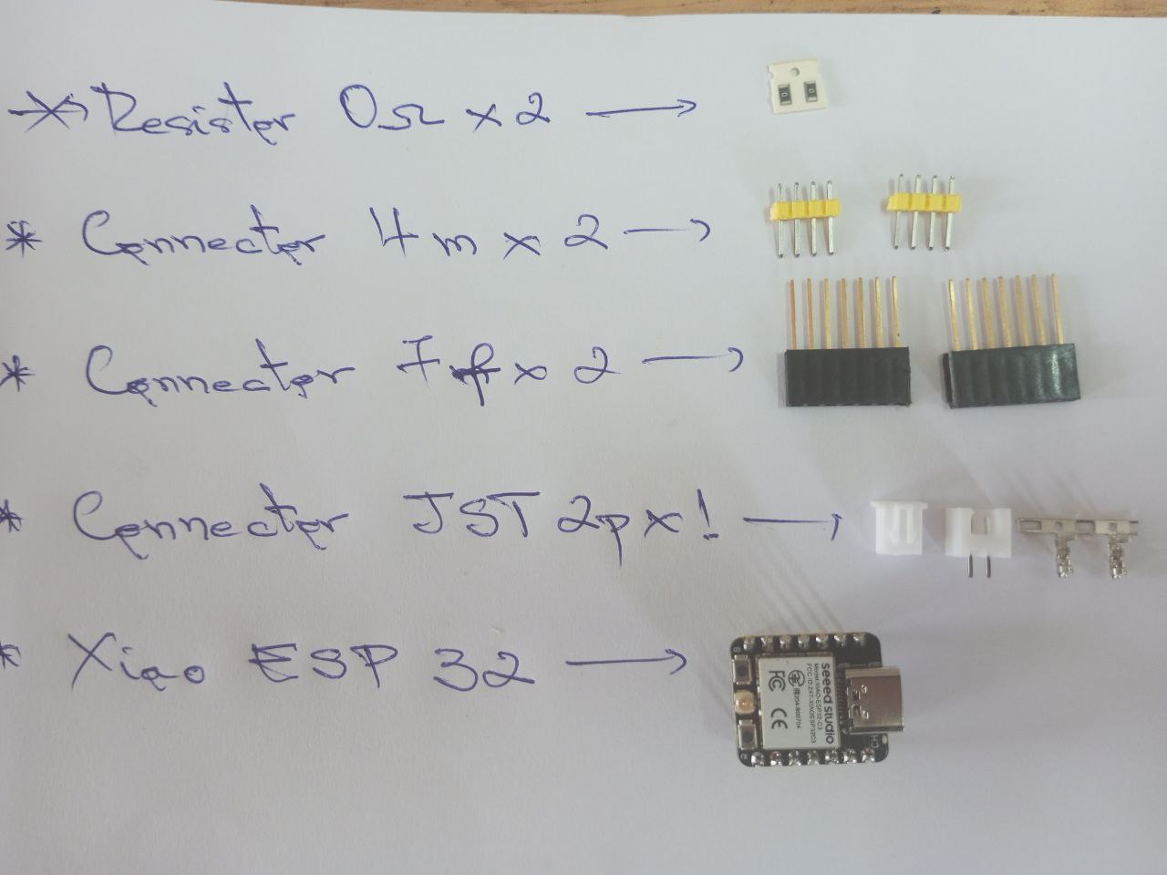
- To start soldering, I’ve drawn up a list of the various components to be soldered.
- Then the soldering of the various components.
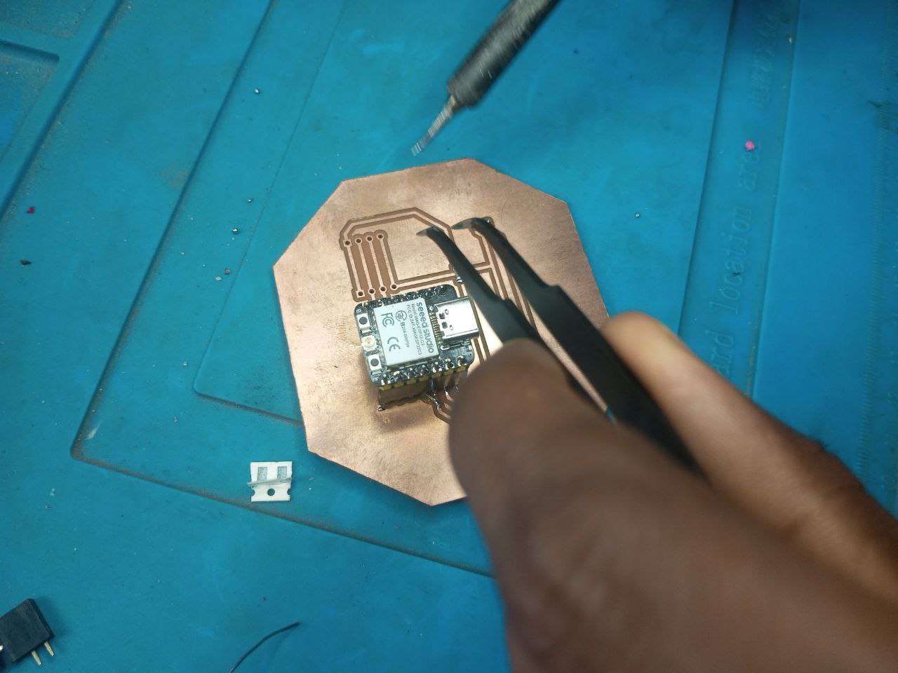
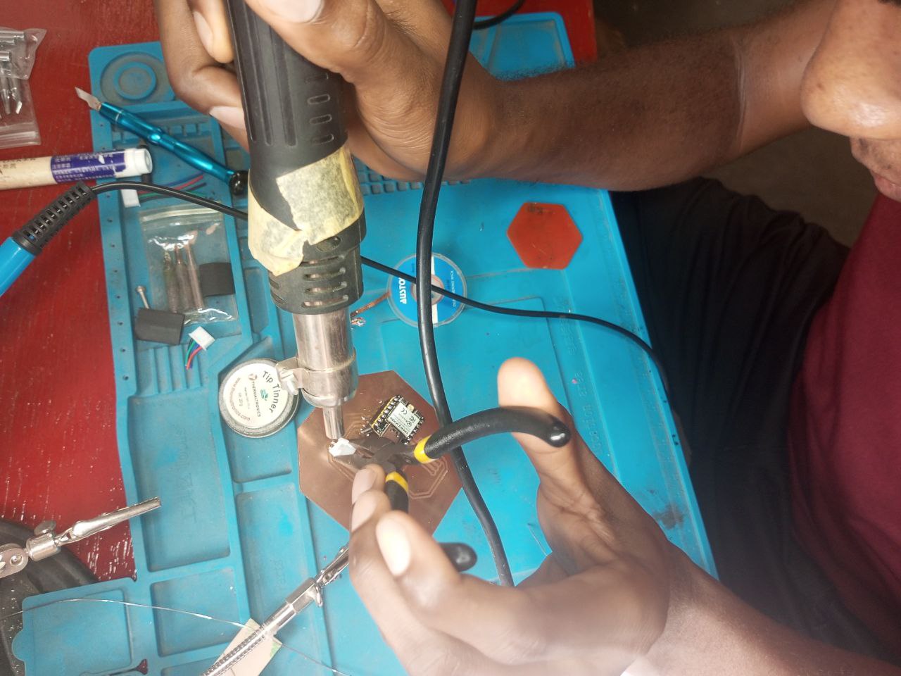
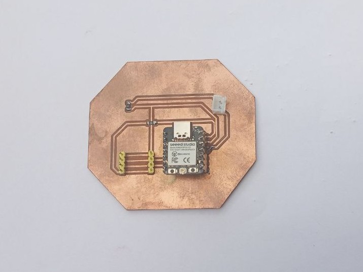
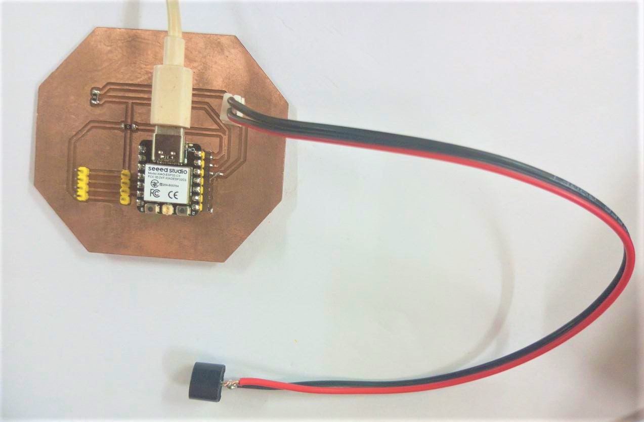
After soldering the components, we obtained this result.
Programming the microcontroller
To program the microcontroller, I wrote an Arduino code for each output device.
- Buzzer program
int buzzer = 10;

void setup() {


}

void loop() {

tone(buzzer,450);
delay(500);
noTone(buzzer);
delay(500);

tone(buzzer,900);
delay(500);
noTone(buzzer);
delay(500);

}
- Program for LCD display
#include <Wire.h>
#include <LiquidCrystal_I2C.h>

LiquidCrystal_I2C lcd(0x27, 16, 2);

void setup()
{

 lcd.begin();


  lcd.backlight();
  lcd.clear();
  lcd.setCursor(0,1);
  lcd.print("Bin Lebene");
}

void loop()
{
}
What went wrong / what went well
Everything went smoothly and there were no major difficulties. It was pretty cool.