14. Interface and application programming
Hero Shots
Assignent Requirements
Group assignment
- Compare as many tool options as possible.
- Document your work on the group work page and reflect on your individual page what you learned.
Individual assignment
Write an application that interfaces a user with input and/or output device(s) on a board that you made.
Group Assignment
Requirements
- Compare as many tool options as possible.
- Document your work on the group work page and reflect on your individual page what you learned.
Link to group assignment page
The group assignment page can be found on the Energylab 2023 website here
it is also embedded directly in the webpage below.
Individual assignment
For this week’s assignment, I used processing software to create the interface that reacts with my input board fitted with the ultrasonic sensor. The aim is to be able to graphically display variations in distance between the sensor and an object. Here’s how it’s done.
Workflow
Step1: How to use Processing
To learn how to use Processing, I mainly used 3 videos, the first of which is available here, the second here and the third here, which explains the principle of communication between the board and Processing. .
To install Processing, you can download it from the official website by clicking here.
Step2: Programming
As I said earlier, the aim is to be able to display graphically the variations in distance between the ultrasonic sensor and an object… To achieve this, programming will be carried out in 2 stages. The first stage will be devoted to programming in Arduino, and the second to programming in processing.
- Programming in the Arduino IDE
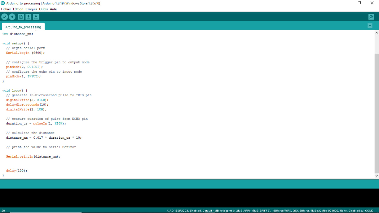
int trigPin = 2;    // TRIG pin
int echoPin = 1;    // ECHO pin

float duration_us;
int distance_mm;
Declaration of the various ultrasonic sensor pins and variables for pulse duration and measured distance.
void setup() {
  // begin serial port
  Serial.begin (9600);

  // configure the trigger pin to output mode
  pinMode(2, OUTPUT);
  // configure the echo pin to input mode
  pinMode(1, INPUT);
}
Configuration of serial communication at 9600 baud with Serial.begin(9600). pinMode() functions are used to set TRIG (2) and ECHO (1) pins to output and input mode respectively.
void loop() {
  // generate 10-microsecond pulse to TRIG pin
  digitalWrite(2, HIGH);
  delayMicroseconds(10);
  digitalWrite(2, LOW);

  // measure duration of pulse from ECHO pin
  duration_us = pulseIn(1, HIGH);

  // calculate the distance
  distance_mm = 0.017 * duration_us * 10;

  // print the value to Serial Monitor

  Serial.println(distance_mm);


  delay(100);
}
Within the loop() function, a 10 microsecond trigger signal is generated by setting the TRIG pin high and then low. The pulseIn() function measures the duration of the return pulse from the ECHO pin.
Taking this pulse duration, the distance is calculated by multiplying the duration by 0.017 (speed of sound in air in millimeters per microsecond) and multiplying by 10 to obtain the distance in millimeters.
Next, the distance value is displayed in the Serial Monitor using Serial.println(distance_mm).
To measure the distance at regular intervals, wait 100 milliseconds with delay(100) before repeating the measurement.
- Programming in Proccessing
import processing.serial.*; //includes the serial object library
Allows you to import the processing.serial library, which is used for serial communication in Processing.
Serial mySerial; //creates local serial object from serial library
Declaration of a “mySerial” variable of type Serial, which will be used to establish a serial connection.
String myString = null; // a variable to collect serial data
Declaration of a “myString” variable of type String and initialization to null. This variable will be used to store data received via serial communication.
int nl = 10; //ASCII code for carage return in serial
Declaration of an “nl” variable of type int and initialization to the value 10, which corresponds to the ASCII code for the newline character.
float myVal; // float for storing converted ascii serial data
Declaration of a myVal variable of type float, which will be used to store serial data converted into numbers.
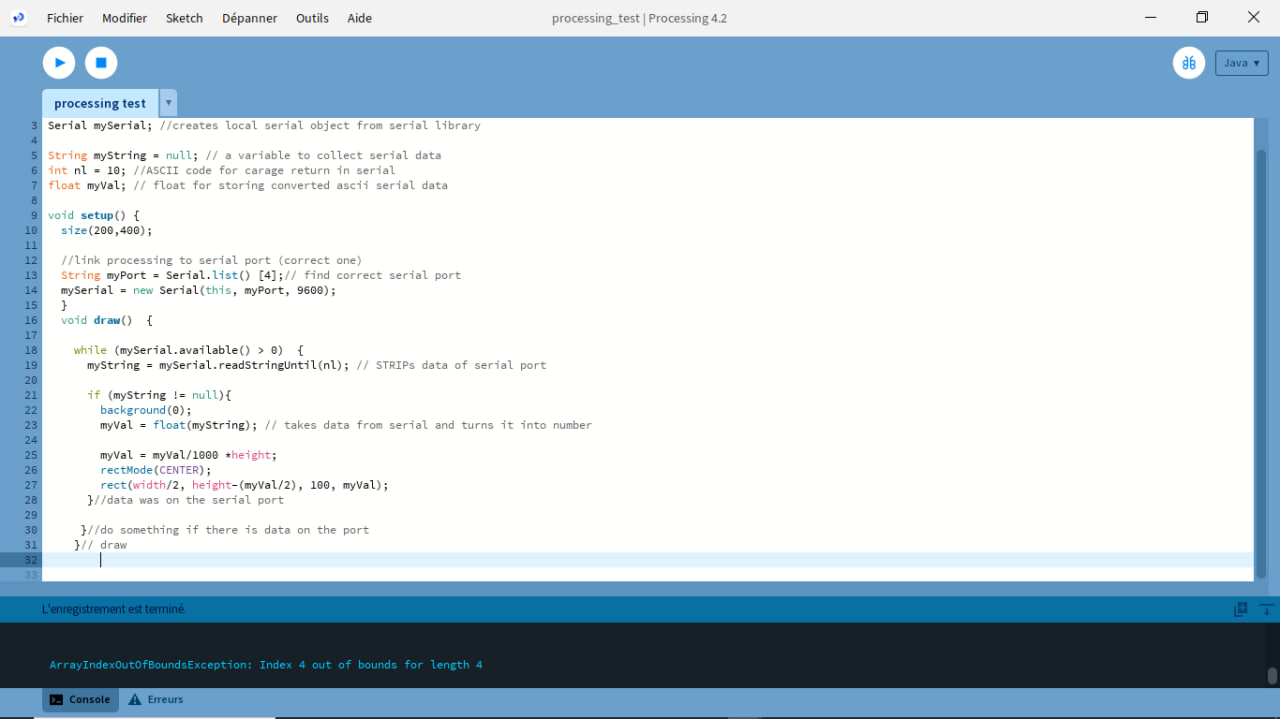
void setup() {
  size(200,400);

  //link processing to serial port (correct one)
  String myPort = Serial.list() [4];// find correct serial port
  mySerial = new Serial(this, myPort, 9600);
  }
The “setup()” function determines the appropriate serial port using “Serial.list()[4]” (meaning that the fifth available serial port will be used). Next, the “Serial()” function creates a new Serial object called “mySerial” which is associated with this serial port and uses a communication speed of 9600 baud.
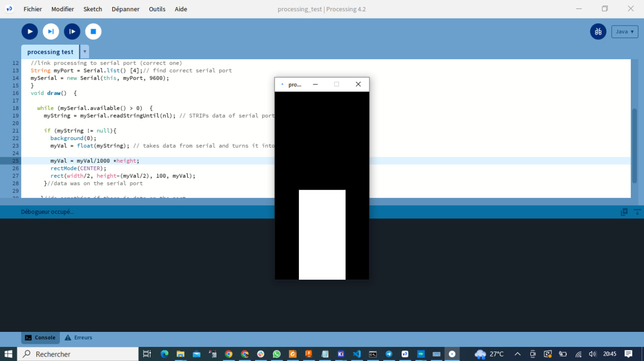
``` void draw() {
while (mySerial.available() > 0)  {
  myString = mySerial.readStringUntil(nl); // STRIPs data of serial port

  if (myString != null){
    background(0);
    myVal = float(myString); // takes data from serial and turns it into number

    myVal = myVal/1000 *height;
    rectMode(CENTER);
    rect(width/2, height-(myVal/2), 100, myVal);
  }//data was on the serial port

 }//do something if there is data on the port
}// draw
```
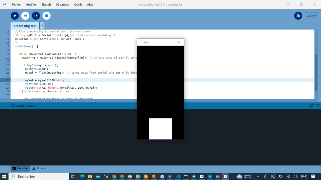
After setup(), the draw() function is executed in a loop. It is responsible for drawing in Processing’s graphics window.
The while condition (mySerial.available() > 0) checks whether data is available on the serial port. If so, mySerial.readStringUntil(nl) reads the serial data until a newline character is encountered (defined by nl), and stores it in myString.
After this, the code checks whether myString is not null, meaning that valid data has been received. In this case, background(0) sets the graphic background to black, float(myString) converts myString to a floating number and stores it in myVal.
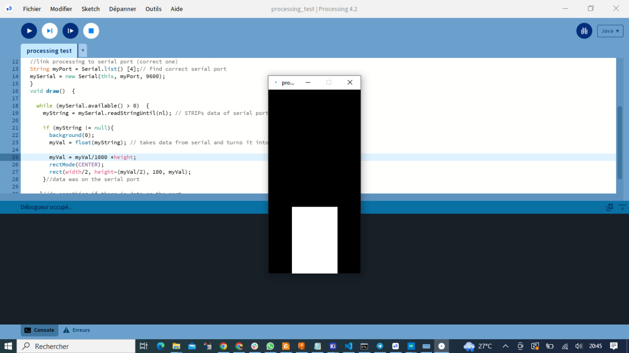
The value of myVal is then used to resize a rectangle in the graphics window. The height of the rectangle is calculated as a function of myVal, and the rectangle is centered horizontally using rectMode(CENTER). The rect() function then draws the rectangle at the specified location.
This code reads the serial data from the sensor and uses it to draw a rectangle in Processing’s graphics window.
Step3: Result
What went wrong / what went well
This week was special because I discovered a new and very interesting software called “Processing”. I didn’t have any major difficulties as I found lots of resources on the Internet and with the help of my colleagues everything went smoothly.