07. Computer controlled machining
Hero Shots
Assignent Requirement
Group assignment:
-
Complete your lab’s safety training
-
Test runout, alignment, fixturing, speeds, feeds, materials and toolpaths for your machine
-
Document your work to the group work page and reflect on your individual page what you learned
Individual project
Make (design+mill+assemble) something big
Group Assignment
Requirements: - Complete your lab’s safety training
-
Test runout, alignment, fixturing, speeds, feeds, materials and toolpaths for your machine
-
Document your work to the group work page and reflect on your individual page what you learned
Link to group assignment page
The group assignment page can be found on the Energylab 2023 website here
it is also embedded directly in the webpage below.
Individual assignment
Requirements
Make (design+mill+assemble) something big
Workflow
For this week’s work, I’ll be cutting and assembling the wooden garbage can that will make up my final project.
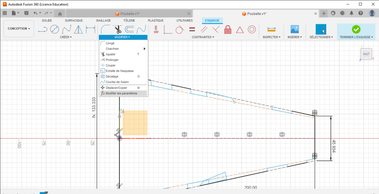
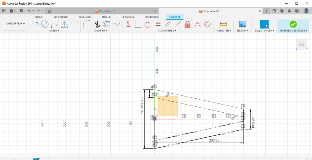
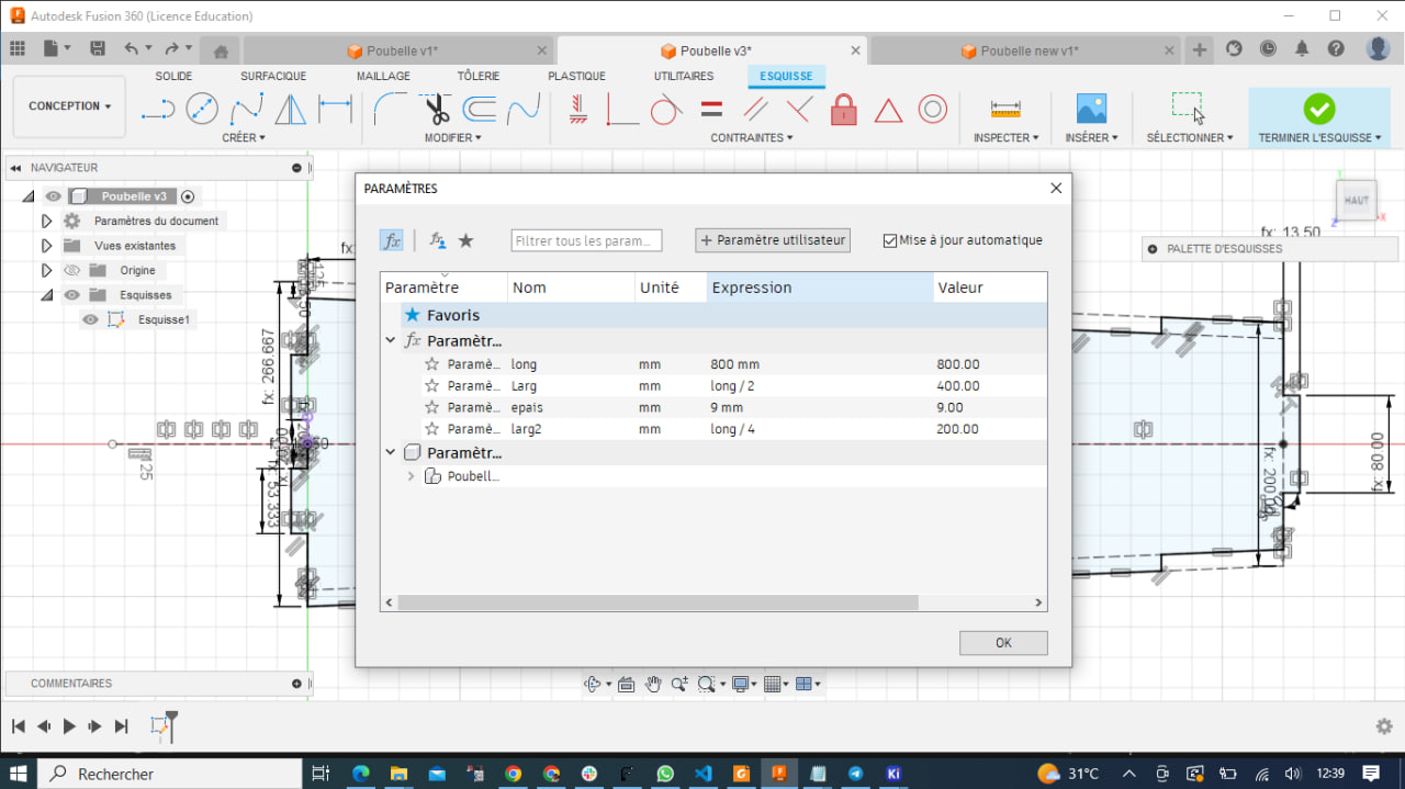
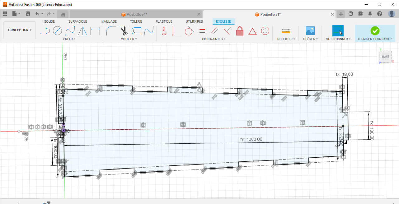
Step 1: Modelisation
fusion 360
For the modeling, I used the model I made in week 3 (Computer controlled cutting). As it’s a parametric model, I’ve just changed the parameter values again to get the size I want.
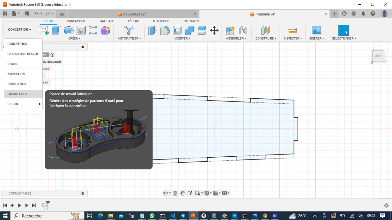
Gcode
After modeling, we need to generate its gcode so that we can import it into our CNC machine software for cutting. In the gcode we’ll enter the necessary parameters so that we can get a good result after cutting.
To generate the gcode with Fusion 360, I had to install a post-processor for Fusion 360. For the installation I was helped by a colleague of ours by following the steps below:
Installation:
The post processor consists of a single file, mpcnc.cps.
It can be simply installed by selecting Manage->Post Library from theFusion 360menubar; alternatively the mpcnc.cps can be copied into a directory and selecting each time prior to a post operation.
If there is an existing mpcnc.cps installed select it prior to installing and use the trash can icon to delete it
The desired post processor can be selected during a post using the Setup button and selecting Use Personal Post Library Use the Job: CNC Firmware property to select between Marlin 2.x, Grbl 1.1 and RepRap firmware
Adding MPCNC post processor to Fusion 360
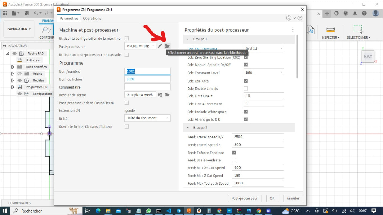
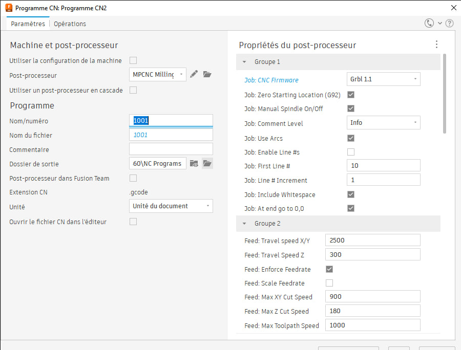
- In Fusion 360 Manufacturing Mode; click on NC program in SETUP section
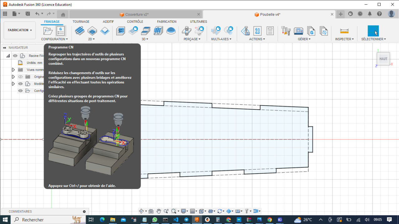
Click on select post processor from library
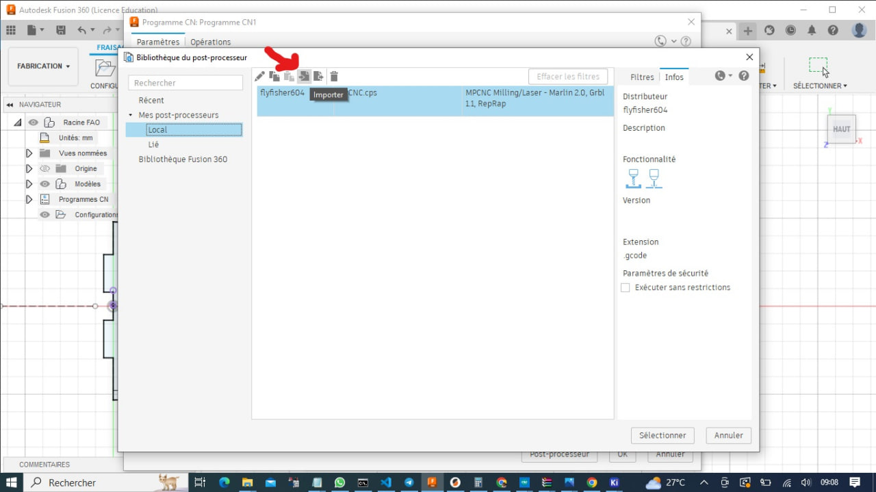
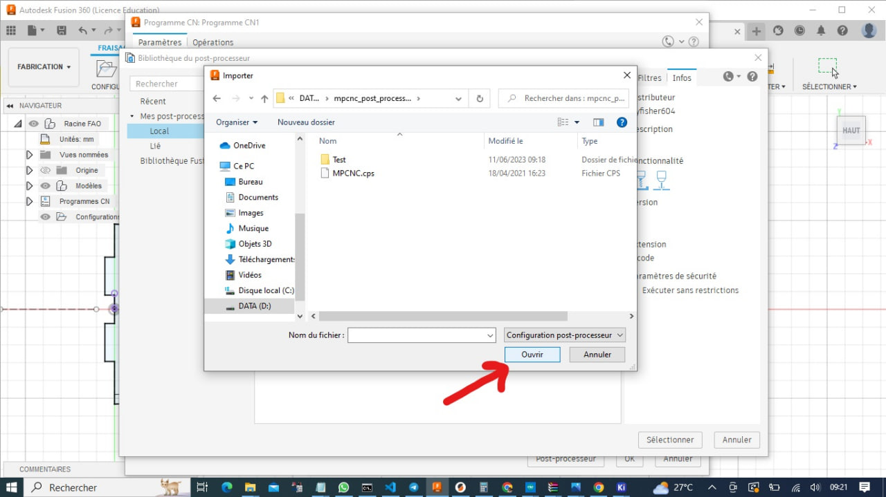
Next Click import in the library windows opened and click on import
Now In new File Explorer window will open prompting to select the post processor to import. Navigate to where you have extracted it and select it;
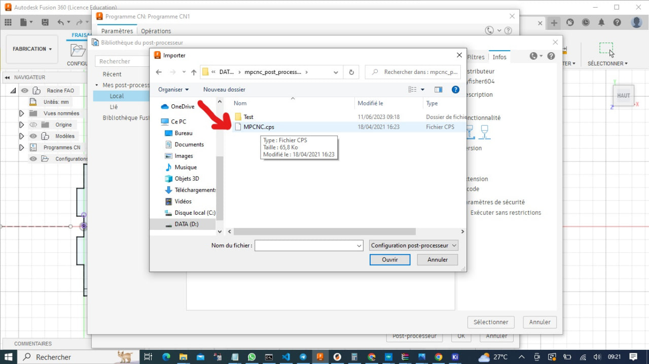
Now click Open
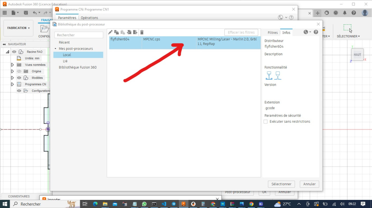
Make sur you clicked on the new post processor
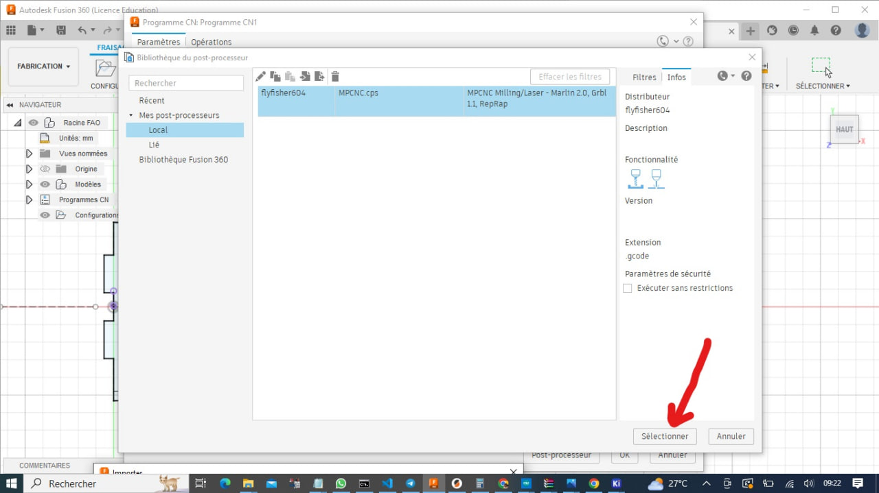
And click select
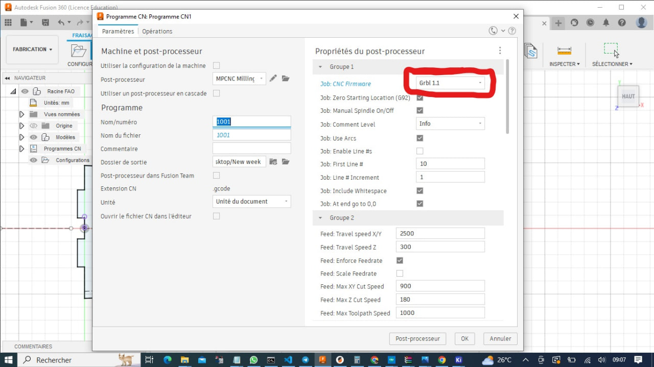
Since this post processor Code for different firmware I have to make sure while generating NcProgram or Gcode to select Grbl1.1
Now that we’ve added the post processor to Fusion 360, we can generate our gcode.
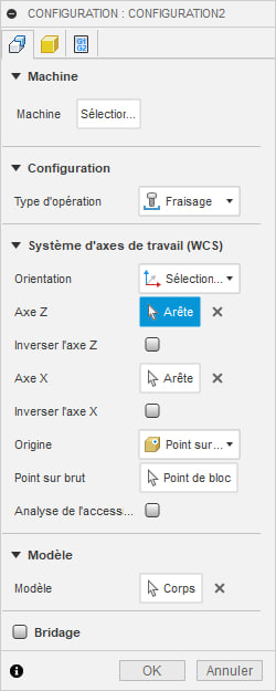
To do this, go back to “Manufacturing” then “Configuration”.
Then this window will open
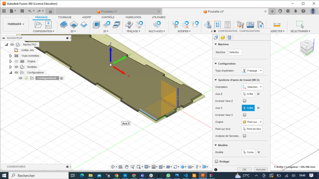
Here we can choose the type of operation we want to perform, as well as the different axes and other parameters required for our cut. Then click on Ok to confirm.
Next, we go to the 2D panel and click on “2D contour”, then this window will open.
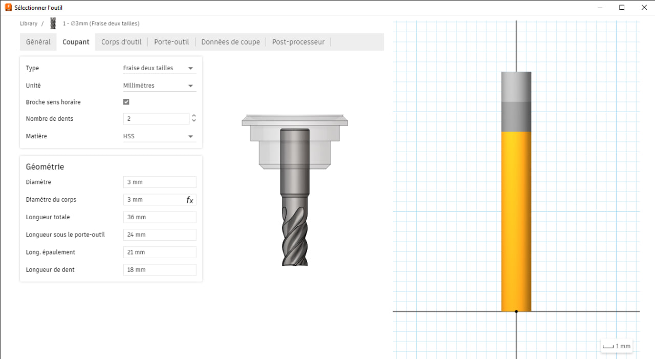
Here we’ll select our cutting tool by clicking on “select” and a new window opens up.
We can then choose a tool from this window according to what we have available for cutting.
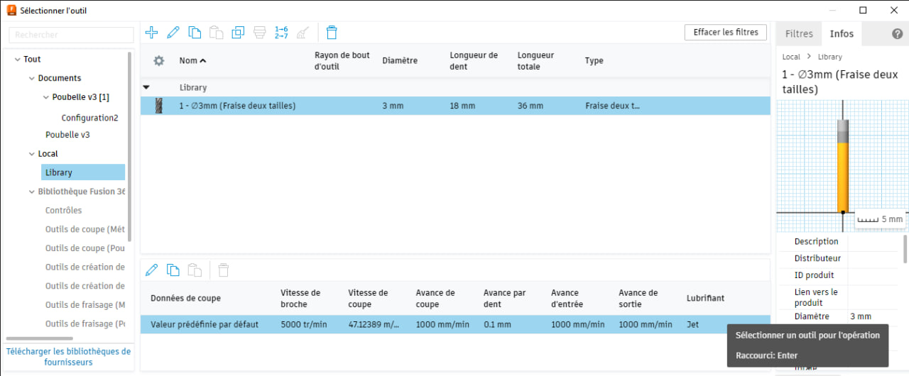
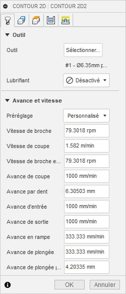
If no tool corresponds to what we want, we can make a modification to get what we want by double-clicking on the tool. This window then opens, and we can make the various modifications.
In the same way, we’re going to modify the other necessary parameters in the “2D contour” window.
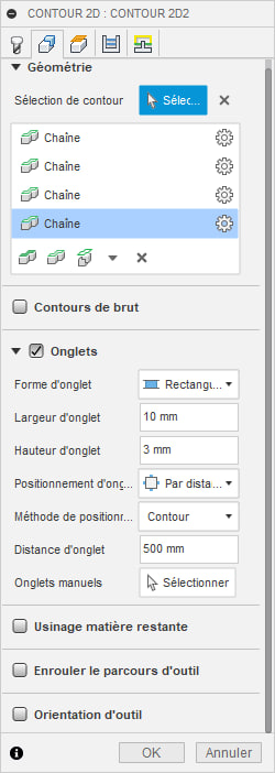
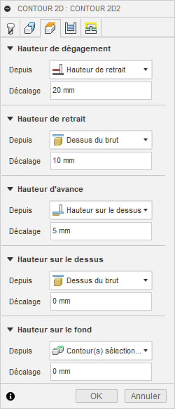
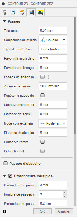
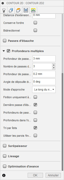
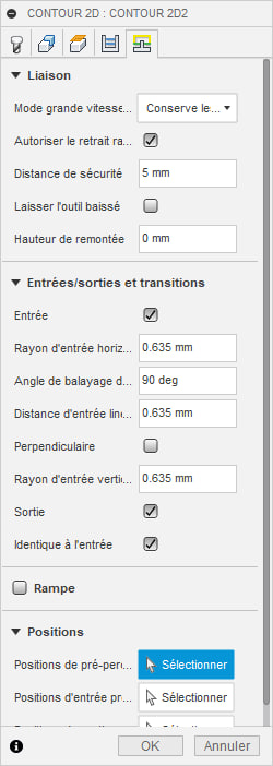
Once we’ve made all the changes, click on “Ok” to confirm.
We can now generate the gcode
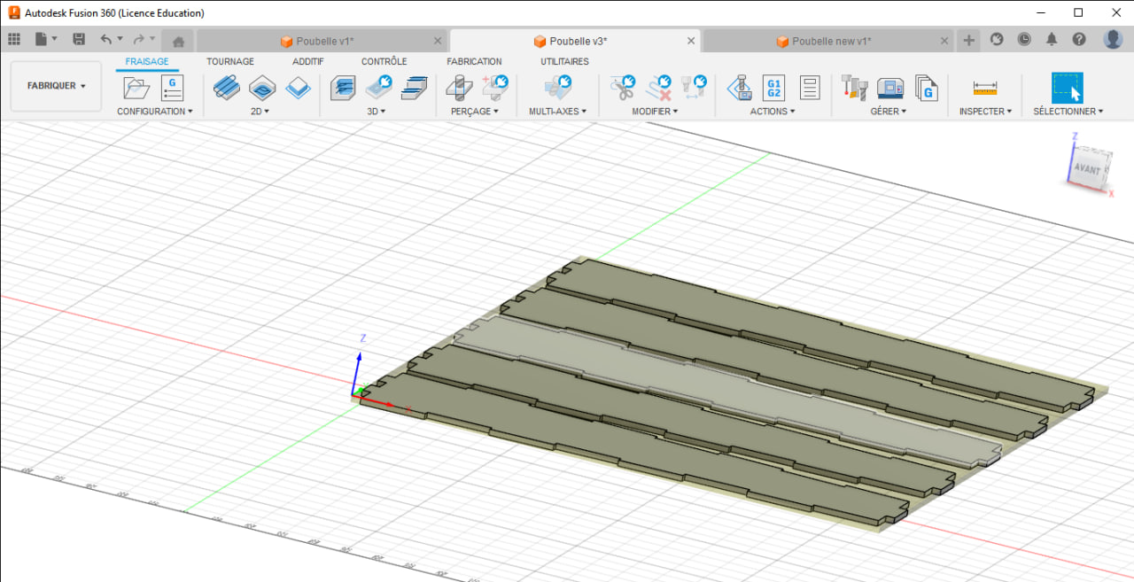
As the garbage can will be made up of several sides, I’ve duplicated the model to be able to cut several at a time and also optimize the space on the material to be cut. Here’s an image of the duplication.
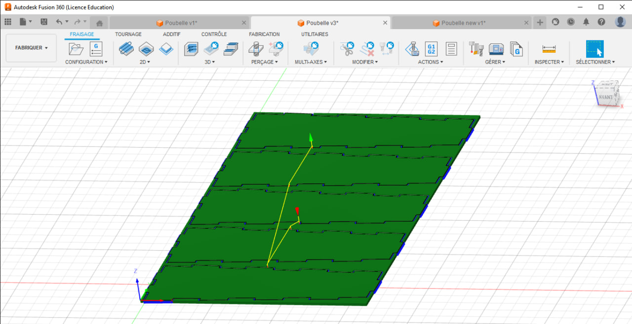
And the different steps to generate our gcode remain the same.
Step 2: Cutting
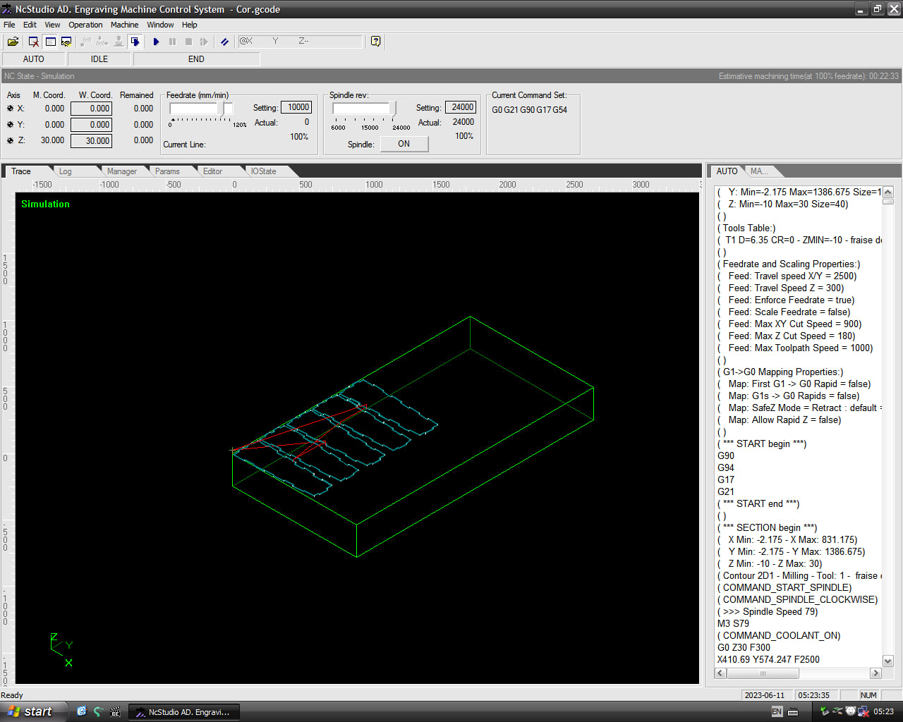
File import into software
With our gcode we’re now going to use the CNC software to make the cut.
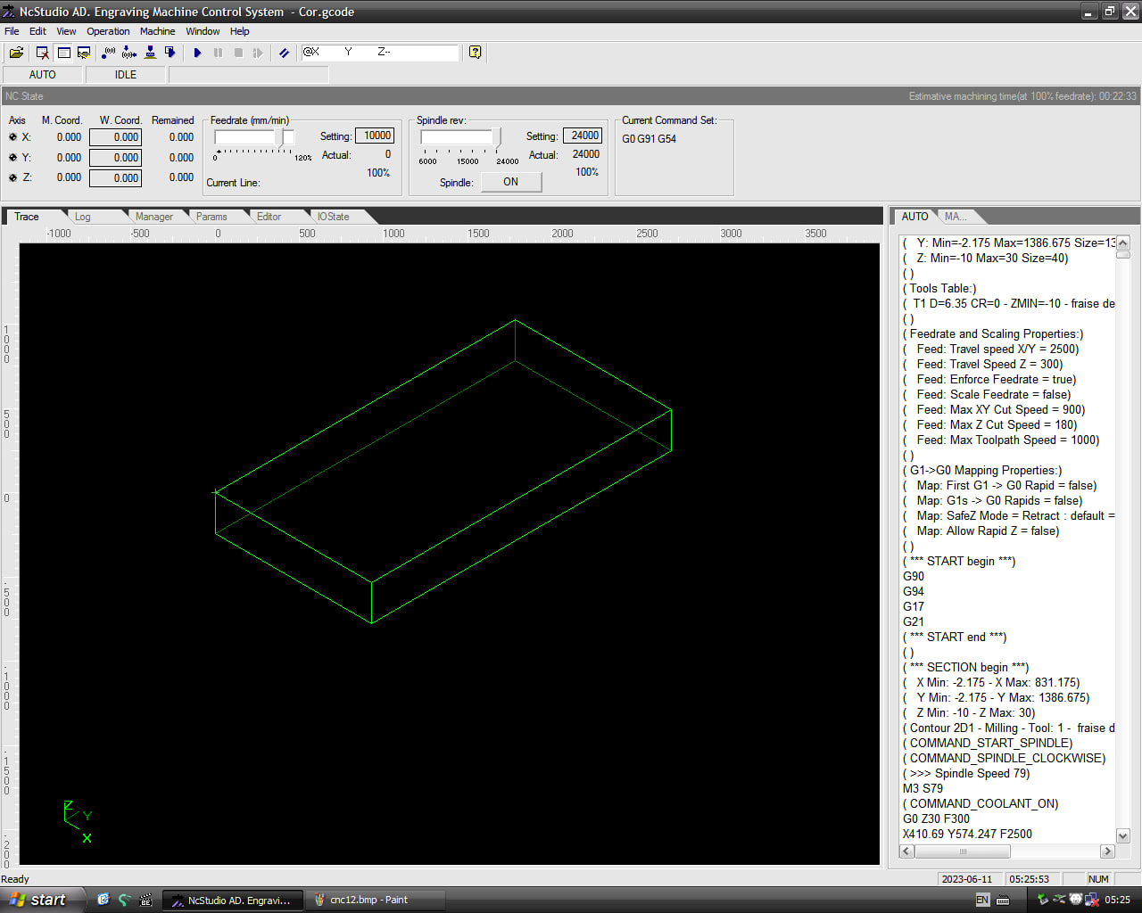
Now we’ll load the file into the software
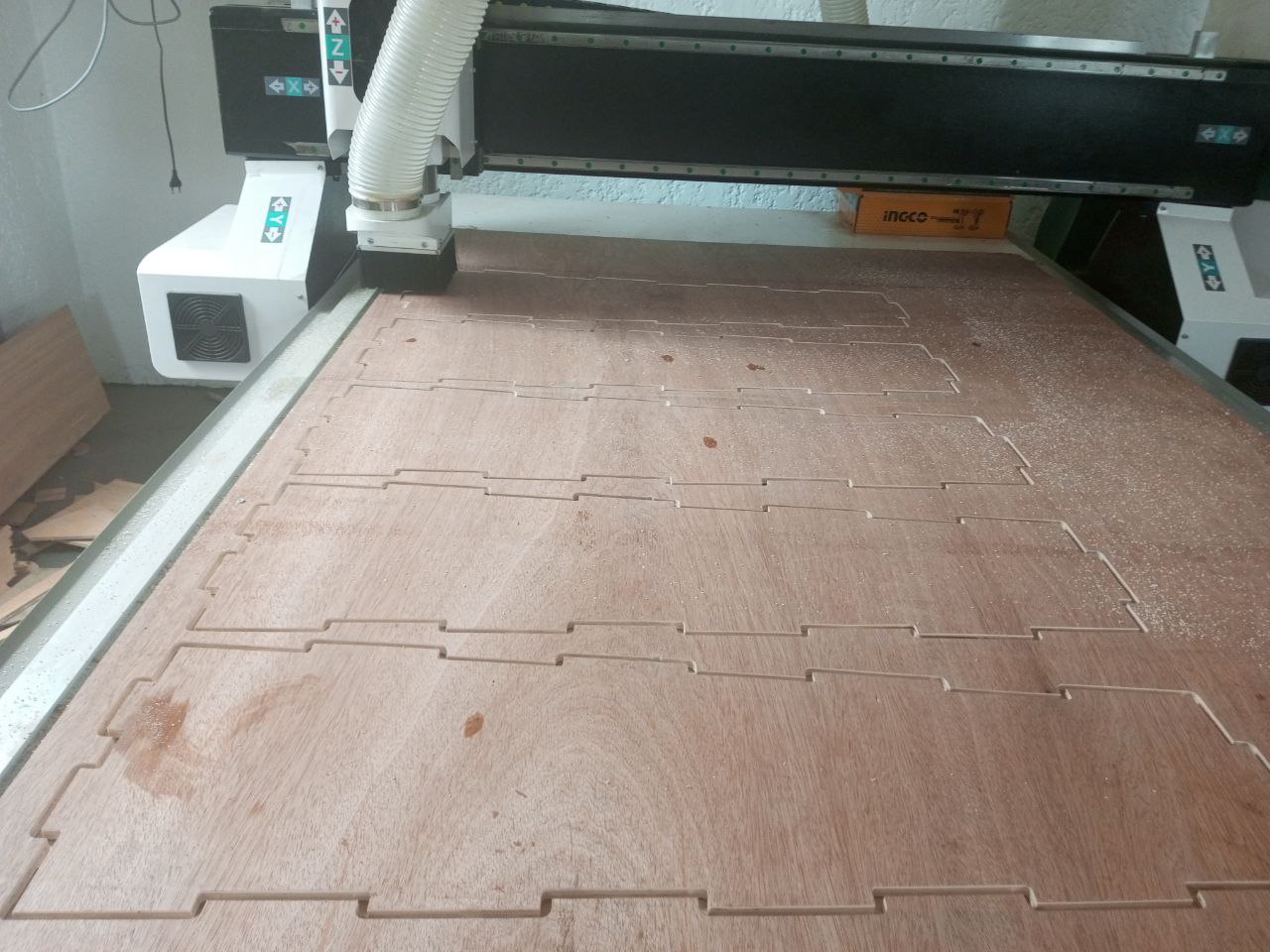
Install cutting material on machine and start CNC
Now it’s time to install the material to be cut on the CNC and start cutting.
Touch-ups
At the end of the cutting process, I removed the cut parts from the machine.
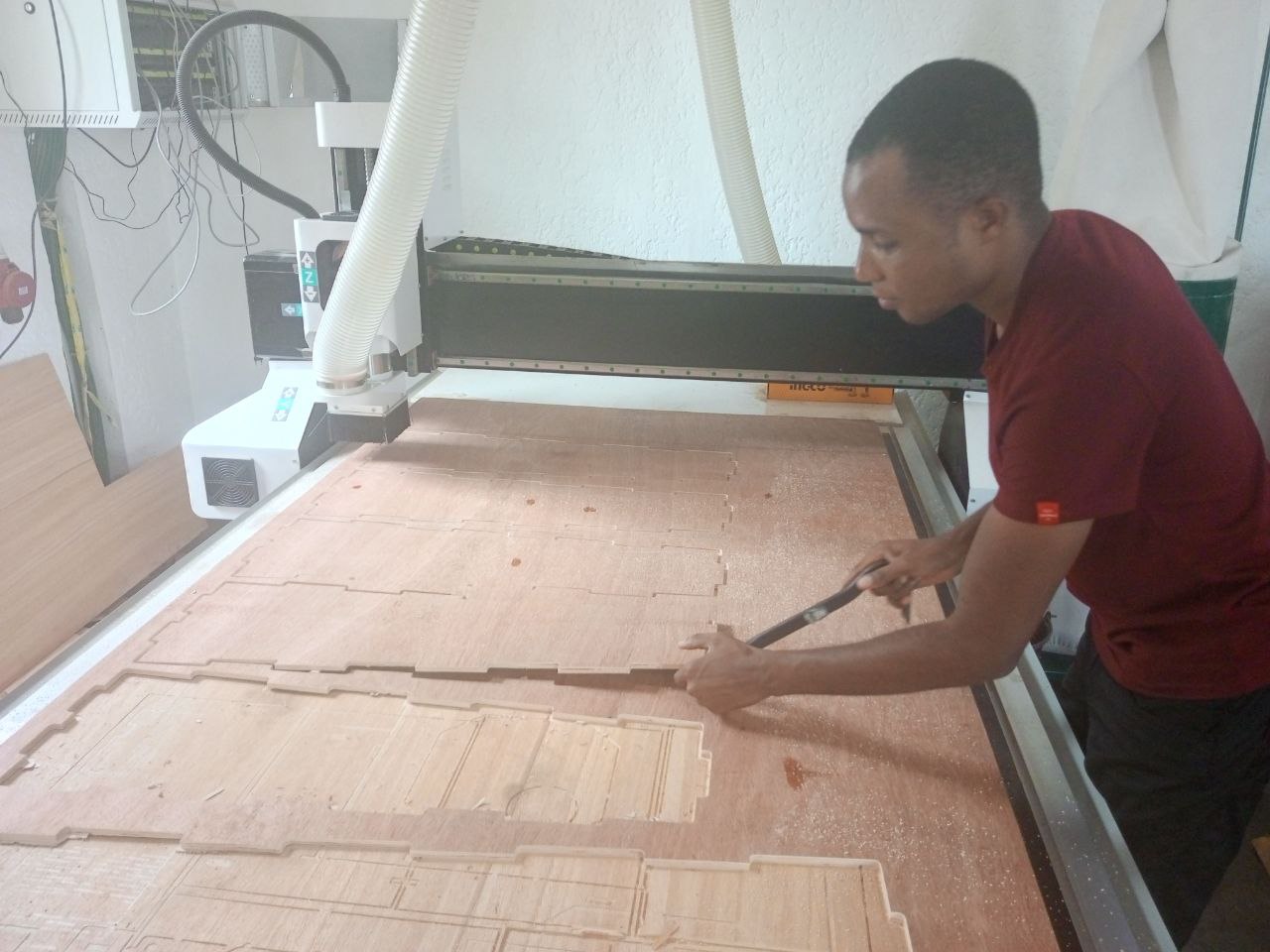
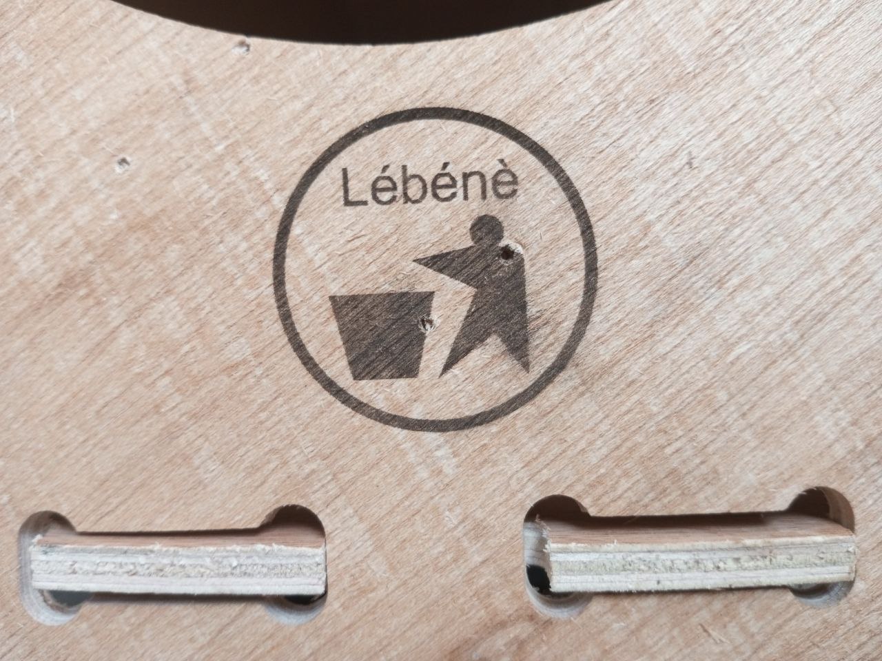
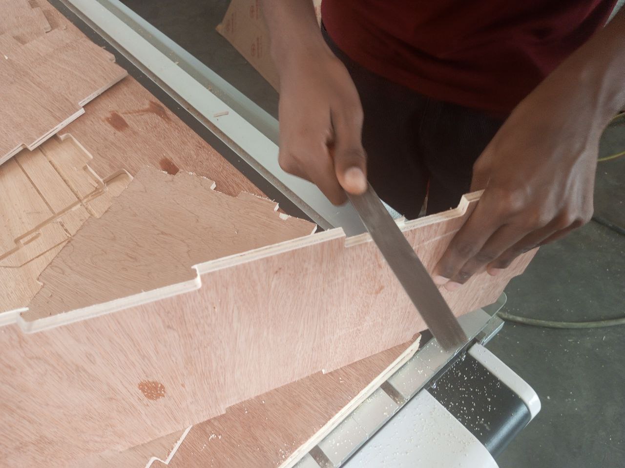
Then file off the parts that need minor finishing.
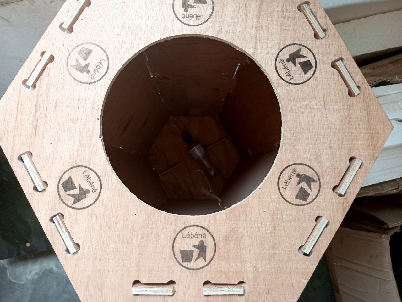
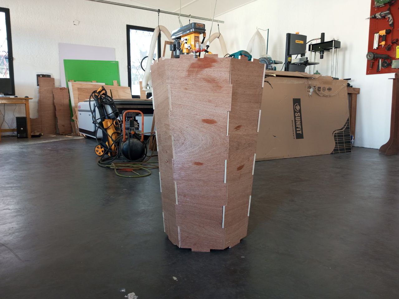
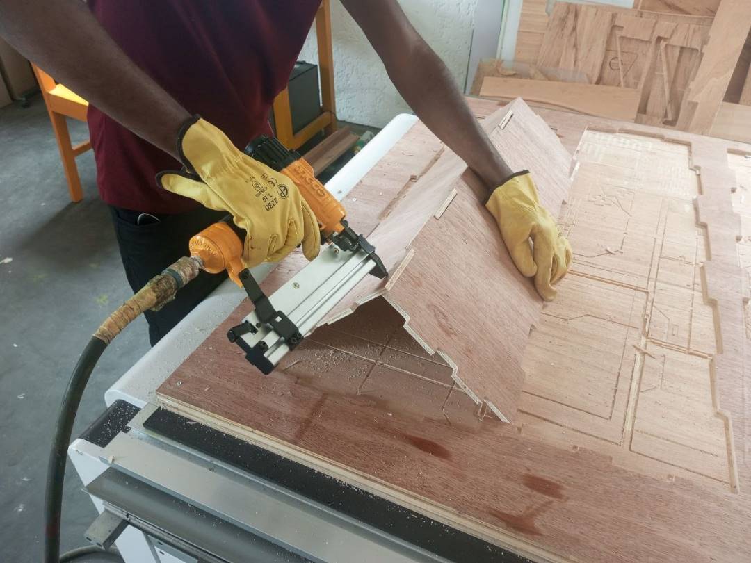
Step 3: Assembly
After cutting, I assembled the parts.
Final Result
What went wrong / what went well
This week, everything went smoothly. However, I did run into a few difficulties:
I have to say that during production, I realized that it wasn’t a very good idea to directly use the same modeling for laser cutting and CNC milling. Because after milling in the CNC, due to the absence of a dog-bone system at the corners, I had to file down the various corners a little to ensure proper assembly.
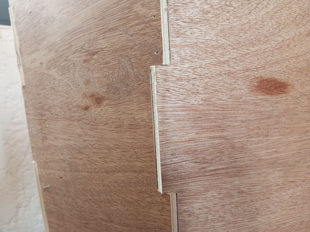
But for the rest of the garbage can parts, such as the lid, I fitted the dogbone system and, taking into account the Kerf value, everything worked fine.