11. Input devices
Hero Shots
Assignment Requirements
Group assignment:
- Probe an input device(s)’s analog and digital signals
- Document your work on the group work page and reflect on your individual page what you learned
Individual assignment:
Measure something: add a sensor to a microcontroller board that you have designed and read it.
Group Assignment
Requirements:
- Probe an input device(s)’s analog and digital signals
- Document your work on the group work page and reflect on your individual page what you learned
Link to group assignment page
The group assignment page can be found on the Energylab 2023 website here
it is also embedded directly in the webpage below.
Individual assignment
Here’s what I did to complete the individual task of adding an input device to a microcontroller and programming it to perform a specific task:
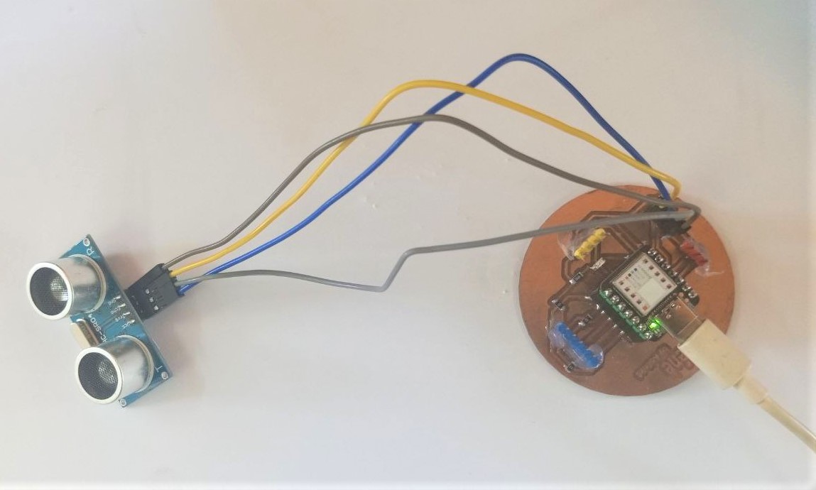
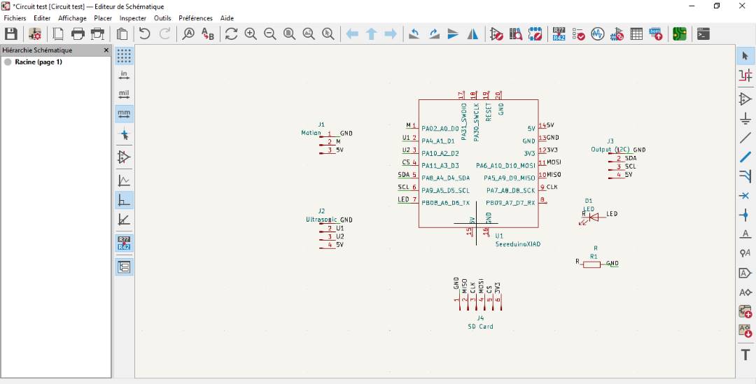
I used a motion detector and an ultrasonic sensor as input devices, then a XIAO SAMD21 microcontroller to control them. With the ultrasonic sensor, we’ll be able to measure distances.
- Motion detector
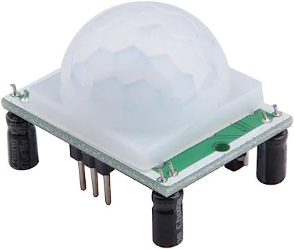
Description
The PIR or Passive Infrared Sensor module is based on the detection of infrared radiation emitted by humans and warm-blooded animals.
Specification
| Features | Value |
|---|---|
| Model | HC-SR501 PIR |
| Supply voltage | 5V - 20V |
| Range | 7m |
| Detection cone | 110 |
| Number of pins | 3 |
| Current consumption | 65mA |
| Digital signal output voltage | 3.3V, 0V |
| Operating temperature | -15°C to +70°C |
| Dimensions | 32x24x26mm (Length x Width x Height with lens) |
| Lateral distance to mounting holes | 28mm |
| Lens diameter | 23mm |
| Weight | 6 g |
Operating principle
The PIR sensor consists of a lens that divides its field of vision into several zones. Each zone has a passive infrared detector. When a person or a warm object crosses the sensor’s field of view, the passive infrared detectors detect the different heat variations emitted by the object. The electrical signals generated by the passive infrared detectors are then amplified and converted into digital signals by an integrated circuit. The PIR sensor then sends a digital signal to the microcontroller, indicating the detection of movement.
Connection
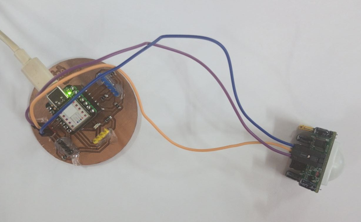
Connect the motion detector’s VCC pin to the XIAO SAMD21’s 5V power supply pin (VCC). A resistor can also be used if the motion detector requires a different voltage (e.g. if the motion detector operates at 5V, use an appropriate resistor to lower the voltage to 3.3V). Next, connect the GND pin of the motion detector to the ground pin (GND) of the XIAO SAMD21.v Finally, connect the OUT pin of the motion detector to a digital pin on the XIAO SAMD21.
- Ultrasonic sensor
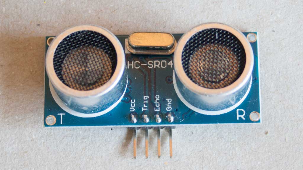
Description
The ultrasonic distance sensor evaluates the distance of an object from the sensor.
Specification
| Features | Value |
|---|---|
| Model | HC-SR04 |
| Supply voltage | 3.3 or 5 Vdc |
| Current consumption | 15 mA |
| Frequency | 40 kHz |
| Range | 2 cm to 4 m |
| Trigger | 10µs TTL positive pulse |
| Echo signal | positive TTL pulse proportional to distance |
| Calculation | distance (cm) = pulse (µs) / 58 |
| Dimensions | 45 x 20 x 18 mm |
| Mounting holes | 1.8 mm |
Operating principle
This sensor consists of an ultrasonic transmitter and an ultrasonic microphone. When the transmitter (loudspeaker) sends out an ultrasound signal, this is reflected by the object in front of it, and the sound then returns to the sensor’s ultrasound microphone. By measuring the time between emission and reception of the sound, and knowing that the speed of sound is 340.29 m / s, we can deduce the distance.
Connection
Connect the VCC pin of the ultrasonic sensor to the 5V power supply (VCC) of the XIAO SAMD21.
Then connect the GND pin of the ultrasonic sensor to the ground pin (GND) of the XIAO SAMD21.
Then connect the Trig pin of the ultrasonic sensor to an available digital pin on the XIAO SAMD21.
Finally, connect the Echo pin of the ultrasonic sensor to another digital pin available on the XIAO SAMD21.
- XIAO SAMD21
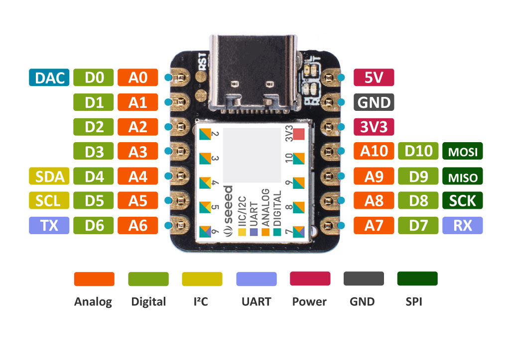
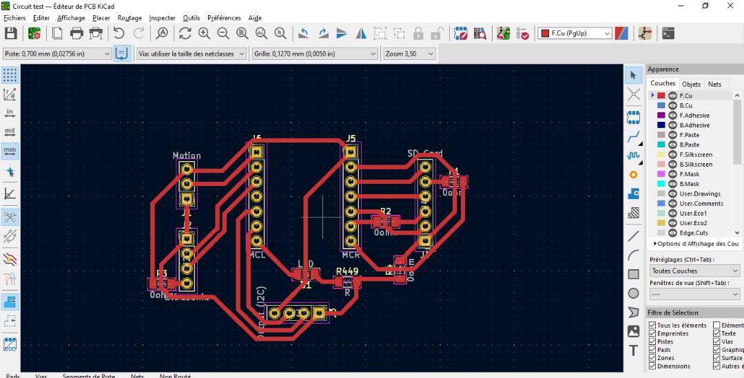
As for my board, I carried out the design in week 6 (Electronics design) and the production and soldering of the pins in week 8 (Electronics production).
Here are the different steps I took to build my board:
To start with the design, I did some research to identify the different pins and functionalities of my microcontroller.
- After that, I started by creating a schematic of my board in KICAD.
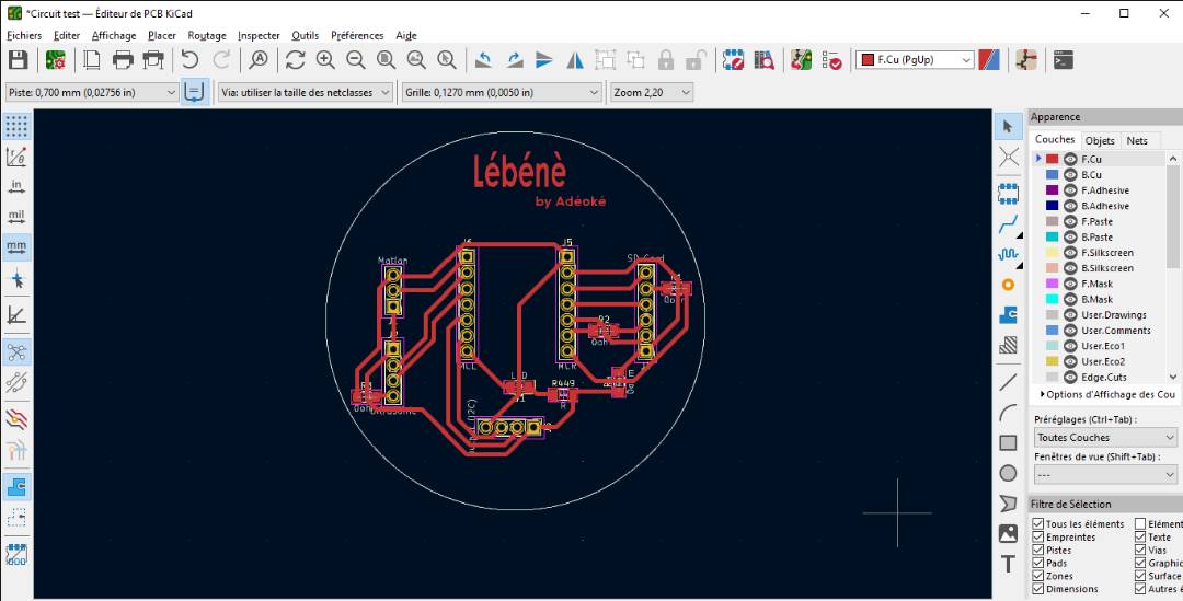
- After the schematic, I moved on to making the PCB, again in KICAD.
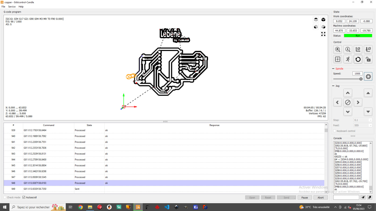
- Then I switched to Flatcam to generate the Gcode.
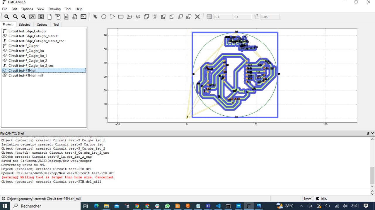
- After generating the Gcode, let’s move on to milling
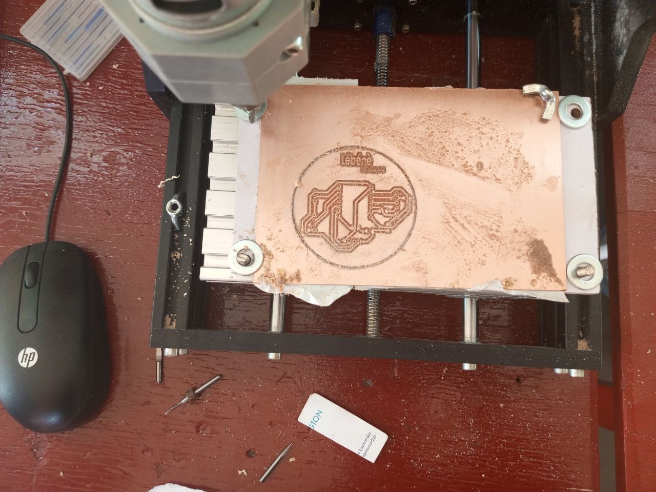
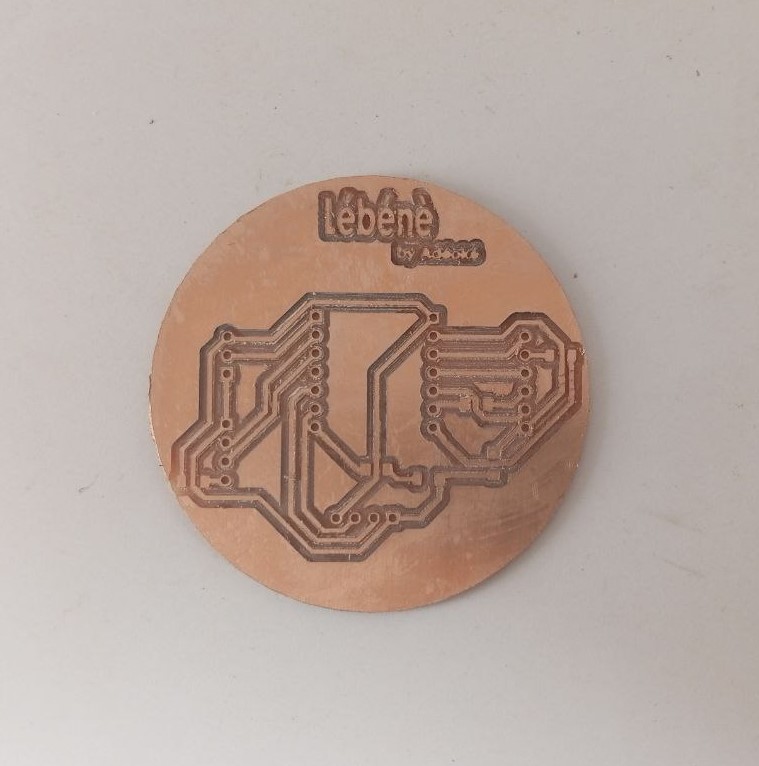
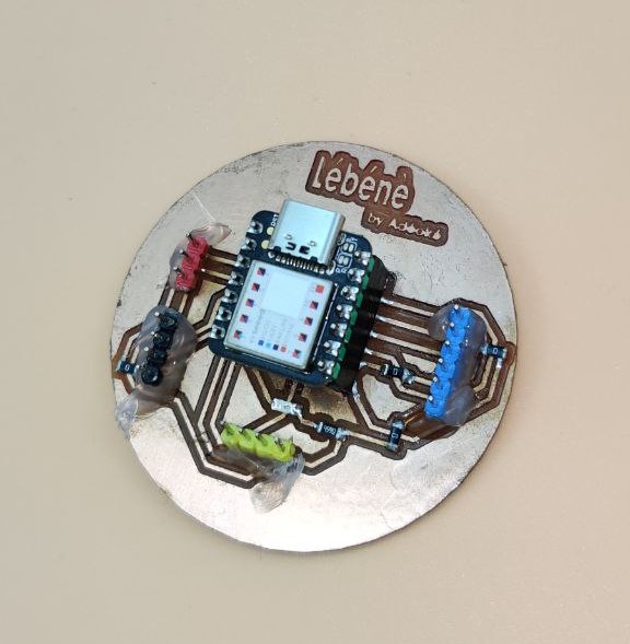
Now that we’ve got our board, let’s move on to soldering the various pins on the board.
To start soldering, I’ve drawn up a list of the various components to be soldered.I then soldered these components onto the board, and here’s the result.
Programming the microcontroller
To program the microcontroller, I wrote an Arduino code for each input device.
- Ultrasonic program
int trigPin = 2;    // TRIG pin
int echoPin = 1;    // ECHO pin

float duration_us;
int distance_mm;

void setup() {
  // begin serial port
  Serial.begin (9600);

  // configure the trigger pin to output mode
  pinMode(2, OUTPUT);
  // configure the echo pin to input mode
  pinMode(1, INPUT);
}

void loop() {
  // generate 10-microsecond pulse to TRIG pin
  digitalWrite(2, HIGH);
  delayMicroseconds(10);
  digitalWrite(2, LOW);

  // measure duration of pulse from ECHO pin
  duration_us = pulseIn(1, HIGH);

  // calculate the distance
  distance_mm = 0.017 * duration_us * 10;

  // print the value to Serial Monitor

  Serial.println(distance_mm);


  delay(3000);
}
In this video, I’m measuring the distance between the ultrasonic sensor and my hand. This can be seen on the serial monitor.
- Motion detector program
const int PIN_TO_SENSOR = 0;   // the pin that OUTPUT pin of sensor is connected to
int pinStateCurrent   = LOW; // current state of pin
int pinStatePrevious  = LOW; // previous state of pin
int motion = 1;

void setup() {
  Serial.begin(9600);            // initialize serial
  pinMode(0, INPUT); // set xiao seeeduino pin to input mode to read value from OUTPUT pin of sensor
}

void loop() {
  pinStatePrevious = pinStateCurrent; // store old state
  pinStateCurrent = digitalRead(0);   // read new state

  if (pinStatePrevious == LOW && pinStateCurrent == HIGH) {   // pin state change: LOW -> HIGH
    motion == 1;
  }
  else
  if (pinStatePrevious == HIGH && pinStateCurrent == LOW) {   // pin state change: HIGH -> LOW
   motion == 0;
  }

  Serial.println(motion);
}
What went wrong / what went well
As far as this week is concerned, I can say that everything went smoothly and there were no major difficulties.