Wildcard Week
Assignment
- Design and produce something with a digital fabrication process (incorporating computer-aided design and manufacturing) not covered in another assignment,
- documenting the requirements that your assignment meets,
- including everything necessary to reproduce it.
The Metal Magic Land

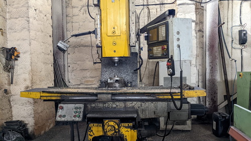
We visited the Steel factory, where we had the opportunity to explore the fascinating world of metal. This visit was made possible through the invitation of Ashot Margaryan, a former student of the Fab Academy.
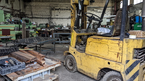
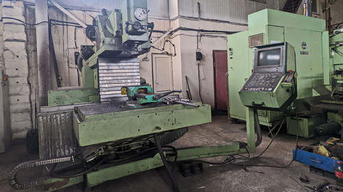
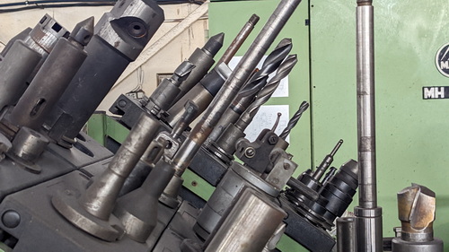
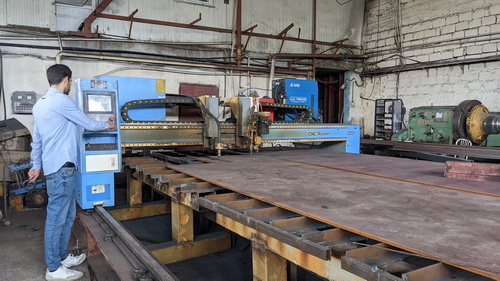
During our visit to the metallurgical plant, we were introduced to a wide array of machines dedicated to working with metal. We encountered Soviet CNC machines, German machines that were over 30 years old, as well as modern Chinese CNC machines.

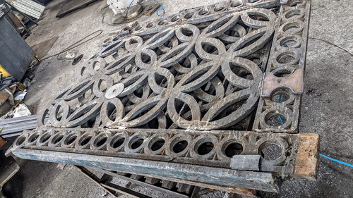
While exploring the factory, we noticed sections of the Victory Bridge from the city of Yerevan being restored by the workers.
Throughout this captivating journey, our friend Ashot accompanied us, providing insightful commentary on how the plant operated and breathed. This experience left a lasting impact on me, igniting a desire to establish a super fablab equipped with metal-working machines. I was inspired by the possibilities that working with metal could offer and the remarkable projects that could be undertaken in such a facility.
Modeling
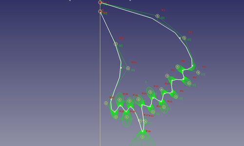
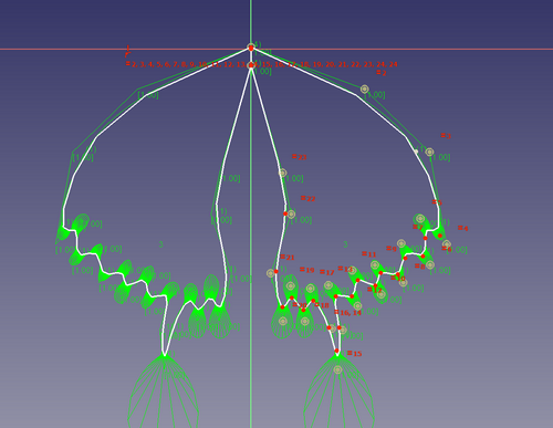
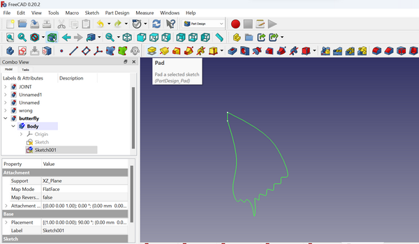
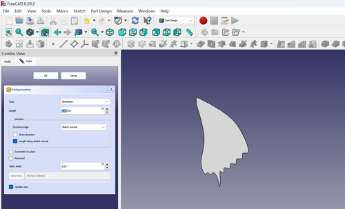
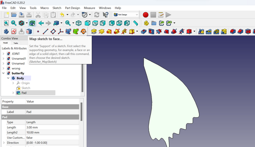
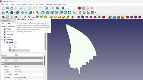
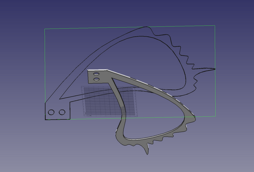
I decided to design butterfly wings using FreeCAD software. Initially, I created a single wing design, and then I duplicated and mirrored it to create the other wing. To visualize the 3D representation, I utilized the “Pad” tool within the software. This allowed me to observe how the wings would appear in their entirety.
This will be a part of my final project. Considering that these wings are relatively small, despite being around 40 cm in length, I decided to incorporate fasteners that would allow them to be attached to a motor for movement. However, upon creating the wings from metal, I recognized that their weight would pose a challenge in terms of mobility. As a result, I devised an alternative solution that you will discover in more detail through my documentation at a later stage.
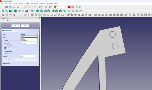
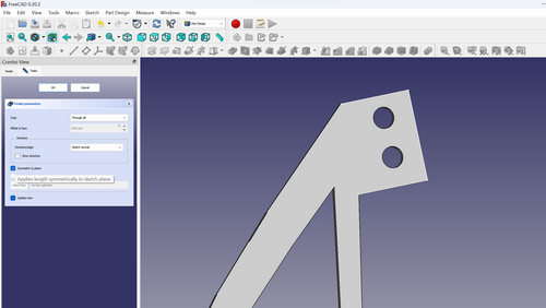
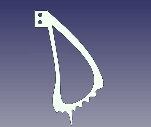
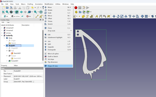
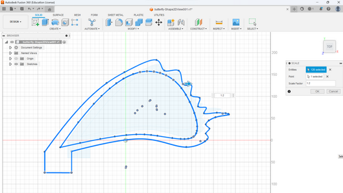
Once the design of the wings was finalized, I followed the familiar process of extracting a 2D shape from the 3D model. This involved utilizing a well-established pattern or technique that I had previously used.
Machining
Among all the impressive machinery, what astonished me the most was the sheer size of the plasma cutter. I had never seen a machine larger than that before in my life.
Since I had limited knowledge about how a plasma cutter operates, I initially assumed that it shared similarities with a laser cutting machine. However, to understand the distinctions between these technologies, I gathered general information from various sources. This research allowed me to gain a better understanding of how plasma cutting and laser cutting differ in terms of their principles and processes.
Laser Cutting vs Plasma Cutting
Laser cutting and plasma cutting are two popular methods used in the field of metal fabrication and industrial manufacturing. While both techniques are effective for cutting through various materials, they employ different mechanisms and offer distinct advantages and disadvantages. Let’s explore the key differences between laser cutting and plasma cutting.
Laser cutting utilizes a high-powered laser beam to melt, burn, or vaporize the material being cut. The laser beam is focused through a lens and directed onto the workpiece, creating a narrow and intense heat-affected zone. This localized heating effectively melts or evaporates the material, forming a clean and precise cut. Laser cutting is known for its exceptional accuracy, fine detail, and narrow kerf width (the width of the cut).
On the other hand, plasma cutting involves the use of a high-temperature plasma arc to cut through materials. A plasma arc is generated by passing an electric current through a gas, typically compressed air or nitrogen. The gas is heated to an extremely high temperature, forming a plasma state. The plasma, along with a high-velocity jet of gas, is directed at the workpiece. The intense heat of the plasma melts the material, while the gas blows away the molten metal, creating the cut. Plasma cutting is renowned for its speed and ability to handle thick materials.
One notable difference between laser cutting and plasma cutting is the type of materials they can effectively cut. Laser cutting is highly versatile and suitable for a wide range of materials, including metals (such as steel, aluminum, and stainless steel), plastics, wood, fabric, and more. It offers excellent precision and is often favored for intricate designs or delicate workpieces.
Plasma cutting, on the other hand, is predominantly used for heavy-duty applications, especially in industries that require cutting through thick metal plates. It excels in cutting conductive materials, particularly ferrous metals like steel, as well as non-ferrous metals like aluminum and copper. Plasma cutting can handle greater thicknesses compared to laser cutting and is commonly employed in metal fabrication, automotive manufacturing, shipbuilding, and construction industries.
The choice between laser cutting and plasma cutting depends on various factors, including the material type, thickness, desired precision, and project requirements. Laser cutting is often preferred for applications that demand intricate details, sharp corners, or thin materials. Plasma cutting, with its speed and ability to handle thick materials, is commonly chosen for heavy-duty and industrial projects.
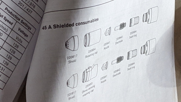
While conducting my research on plasma cutting, I came across the concept of shielded and unshielded cutting, which piqued my interest. Delving into various forums and sources of information, I dedicated time to studying and comprehending how this technique operates. As a result, I have gained a clearer understanding of the differences and mechanisms involved in shielded and unshielded cutting methods.
In shielded cutting, the plasma arc is surrounded by a gas shield that protects the cutting surface from the ambient air. The gas shield can be made of inert gases like argon or nitrogen, or it can be a mixture of gases like argon/hydrogen or argon/nitrogen/hydrogen. The gas shield prevents the plasma arc from reacting with the oxygen and nitrogen in the air, which can cause oxidation and nitriding of the metal, resulting in poor-quality cuts.
In unshielded cutting, the plasma arc is exposed to the ambient air, and there is no gas shield to protect the cutting surface. This type of cutting is typically used for thinner metals and in applications where the quality of the cut is less critical, as it can result in more oxidation and a rougher cut.
The main advantage of shielded cutting over unshielded cutting is the superior quality of the cut. The gas shield protects the cutting surface from oxidation and nitriding, resulting in a cleaner and smoother cut. Shielded cutting also allows for greater control over the cutting process and the ability to cut thicker metals.
In the manual, I discovered additional information specifically related to shielded plasma cutting settings. This valuable resource provided me with detailed insights and guidance on the specific parameters and configurations required for achieving optimal results in shielded plasma cutting.
Preparation for plasma cutting

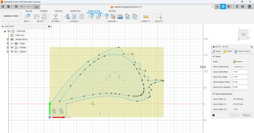
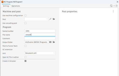
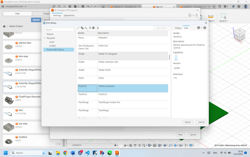
I exported my model from FreeCAD in the .dxf format and proceeded to import it into Fusion. In Fusion, I prepared the drawing and made necessary adjustments to generate the G-code required for plasma cutting. This transition between software allowed me to utilize Fusion’s tools and functionalities specifically tailored for preparing the design for plasma cutting operations.
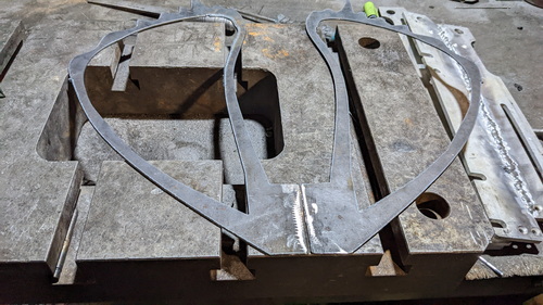
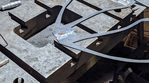
Indeed, it was during this stage that I came to the realization that the wings would be too heavy to be easily maneuvered by a motor. Consequently, I made the decision to remove the joints or holes that were initially intended for attachment to the motor. Instead, I opted to cut out two separate wings and subsequently weld them together.
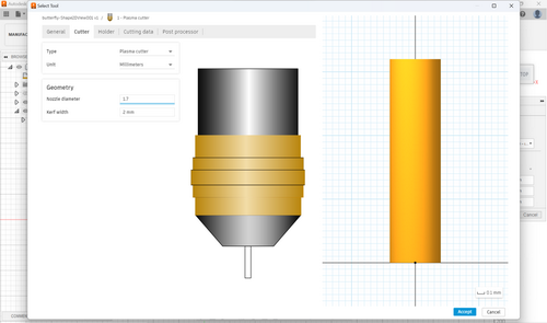
In the Manufacturing Workbench, I made the necessary adjustments to the plasma cutting tool settings. After configuring the tool parameters, I proceeded to simulate the cutting process to visualize and analyze the operation. This simulation provided me with a representation of the cutting process, allowing me to assess and refine the settings as needed before proceeding with the actual plasma cutting.
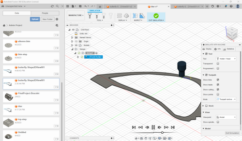
I went Action -> Post Process to generate the G-code
Cutting
Safety first!
I would like to emphasize the utmost importance of safety when working with a plasma cutter. To ensure the well-being of all individuals involved, we were provided with special goggles and gloves specifically designed for plasma cutting operations. Strict safety protocols were implemented, including maintaining a safe distance from the machine during the cutting process. Following the completion of cutting, we handled the hot metal solely with the use of protective gloves. These safety measures were crucial in preventing any potential accidents or injuries and ensuring a secure working environment throughout the plasma cutting process.
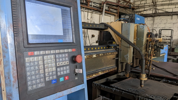
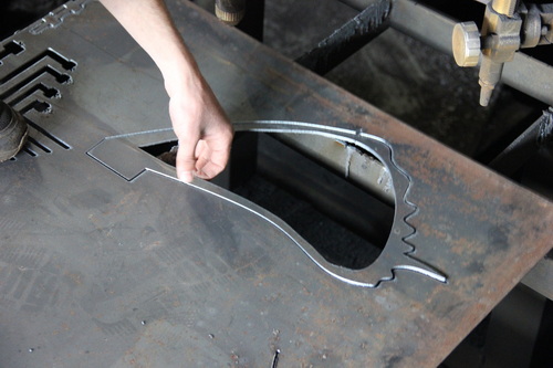
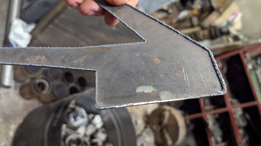
Ashot kindly offered me the opportunity to cut out parts from a 2mm steel sheet. It was the thinnest sheet of steel, I proceeded with the cutting process. Operating the heavy plasma cutting machine using the directional arrows was truly impressive and left a lasting impact.
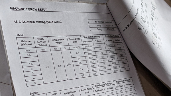
During the plasma cutting process, there are several crucial parameters to consider. These include the selection of appropriate power levels, cutting speed, gas flow rates. By carefully managing these parameters, I aimed to achieve precise and clean cuts while ensuring the longevity of the consumable parts. These factors play a significant role in determining the overall quality of the plasma cutting results.

Welding
Preparing the Metal: The metal pieces being welded should be cleaned thoroughly with a wire brush or grinder to remove any rust, paint, or other debris. This step ensures that the weld will be free of impurities.


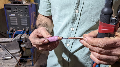
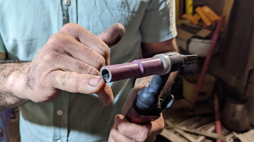
I discovered Tungsten Inert Gas (TIG) welding is a precise and versatile welding process that utilizes a non-consumable tungsten electrode to create the arc and an inert gas, such as argon, to shield the weld area.
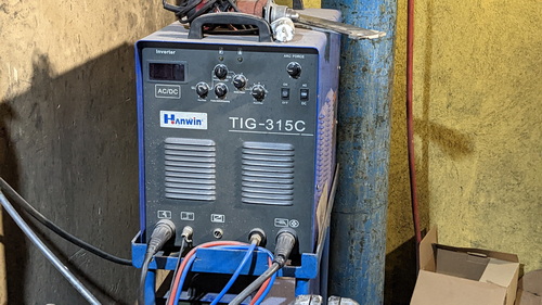
Andranik Margaryan graciously introduced us to the TIG-315C welding machine. With his guidance, we were able to familiarize ourselves with the operation and capabilities of the welding equipment. This introduction provided valuable insights into the welding process, including proper techniques, safety precautions, and the various applications of welding in fabricating metal structures. Andranik’s expertise and guidance were instrumental in expanding our knowledge and skills in the realm of welding.
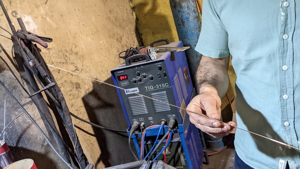
The TIG-315C is a TIG welding machine that provides precise control over the welding process, making it suitable for a wide range of applications. It offers various welding parameters that can be adjusted to achieve optimal results, including current, pulse frequency, pulse duration, and gas flow rate.
With the TIG-315C, welders can work with a variety of metals, including stainless steel, aluminum, copper, and more. The non-consumable tungsten electrode, held in a specialized torch, creates an electric arc that generates intense heat, melting the base metal and forming the weld joint.
Another advantage of the TIG-315C is its ability to perform both AC and DC welding. AC mode is commonly used for welding aluminum and aluminum alloys, while DC mode is suitable for welding other metals such as stainless steel and mild steel. This versatility makes the TIG-315C a valuable tool for various welding applications.
To ensure operator safety, the TIG-315C is designed with built-in protection mechanisms such as thermal overload protection and voltage surge protection. These features help safeguard the machine and the welder, preventing damage from electrical faults or excessive heat.
In welding processes like TIG welding, a cooling system is essential to prevent overheating of the welding torch and other components. Excessive heat can cause damage to the equipment, decrease welding performance, and lead to weld defects. There are two primary types of cooling systems used in TIG welding:
Air-Cooled Systems: Air-cooled systems utilize a fan or fans to circulate air over the welding torch and other parts of the welding setup, such as the power source and cables. The moving air helps dissipate heat and keeps the components within safe temperature limits. Air-cooled systems are typically simpler, more portable, and easier to maintain compared to water-cooled systems. They are suitable for low to moderate welding amperages and are commonly used in light-duty and hobbyist applications.
Water-Cooled Systems (in our case): Water-cooled systems use a coolant, typically a mixture of water and antifreeze, to circulate through a closed loop. This coolant absorbs heat from the welding torch and other hot components, carrying it away from the welding area. The heated coolant then flows through a radiator or heat exchanger, where it dissipates the heat to the surrounding air. Water-cooled systems are more effective at cooling than air-cooled systems and are capable of handling higher welding amperages. They are commonly used in professional and industrial settings where higher heat loads are involved.
Water-cooled systems require additional components, including a water-cooled torch, coolant pump, radiator or heat exchanger, and hoses for coolant circulation. These systems can provide more extended periods of welding before the torch or other components reach their temperature limits, making them suitable for heavy-duty and continuous welding applications.


The welding process proved to be an exhilarating experience, and Andranik’s exceptional skill and expertise were truly inspiring. Witnessing his mastery of welding techniques fueled my desire to further explore and learn this craft. I hope that during my future visits to the factory, I will have the opportunity to immerse myself in the art of welding and develop my own proficiency.
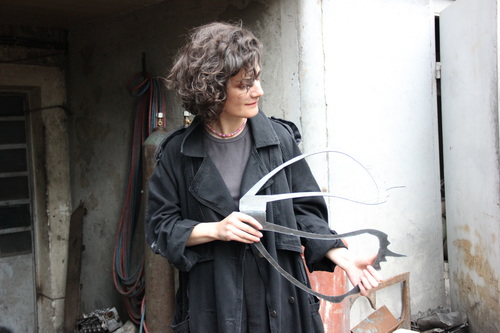
Conclusion
the joy I felt when holding the two wings I created in this unforgettable place was immeasurable. These wings hold a special significance as they will adorn my final project, marking the beginning of my passion for working with metal and creating unique art installations and sculptures. I am excited to continue this journey, exploring new possibilities, and further honing my skills in metalwork.