Networking and communications
Task: Embedded Networking and Communications
Group assignment:
- Send a message between two projects
- Document your work to the group work page and reflect on your individual page what you learned
Individual assignment:
- design, build, and connect wired or wireless node(s) with network or bus addresses
Group Assignment

During the group assignment, we worked on a project involving 2 PCBs (3 microcontrollers) communicating with each other using I2C (Inter-Integrated Circuit) protocol. The objective was to send analog data from a secondary (sender) board to a primary (receiver) board, and based on the received data, control the status of LEDs on the receiver board.
Primary Board Code:
#include <Wire.h>

void setup() {
  // Start the I2C Bus as Master
  Wire.begin();
}
void loop() {
  Wire.requestFrom(5, 1);    // request from device #5
  uint8_t received = -1;
  while (Wire.available()) {
    received = Wire.read();
  }

  uint8_t toSend = map(received, 0, 255, 0, 63);

  Wire.beginTransmission(9); // transmit to device #9
  Wire.write(toSend);              // sends
  Wire.endTransmission();    // stop transmitting
  Serial.print("toSend : ");
  Serial.println(toSend);
  delay(1000);
}
The primary board acts as the I2C master and is responsible for requesting data from the secondary board and controlling the LEDs on the receiver board. It starts the I2C bus and enters the main loop. In each iteration, it requests data from device #5 (secondary board) using Wire.requestFrom() and reads the received data. The received data is then mapped to a new value between 0 and 63 using map(). The primary board then begins transmission to device #9 (receiver board) using Wire.beginTransmission() and sends the mapped value using Wire.write(). Finally, it ends the transmission and waits for 1 second before repeating the process.
Secondary (Sender) Board Code:
#include <Wire.h>

int AnalogPin = 4;
void setup() {

  pinMode(AnalogPin, INPUT);

  Wire.begin(5);                // join i2c bus with address #5
  Wire.onRequest(requestEvent); // register event


}

void loop() {
  delay(100);
}

void requestEvent() {

  int AnalogValue = analogRead(AnalogPin);

  uint8_t mappedNumber = map(AnalogValue, 0, 1023, 0, 255);

  Wire.write(mappedNumber);

  Serial.println(mappedNumber);
}
The secondary board is responsible for reading analog data from an analog pin and sending it to the primary board. It sets up the analog pin as an input and starts the I2C bus with address #5. It registers the requestEvent function to be called when a request is received from the primary board. In the main loop, it adds a delay of 0.1 second. When a request is received, it reads the analog value from the analog pin using analogRead(). The analog value is then mapped to a new value between 0 and 255 using map(). The mapped value is sent back to the primary board using Wire.write().
Secondary (Receiver) Board Code:
const int PIN_GREEN = 0;
const int PIN_RED   = 1;
const int PIN_BLUE  = 2;

const int PIN_GREEN2 = 5;
const int PIN_RED2   = 4;
const int PIN_BLUE2  = 3;

#include <Wire.h>

int x = 0;
void setup() {
  pinMode(PIN_RED,   OUTPUT);
  pinMode(PIN_GREEN, OUTPUT);
  pinMode(PIN_BLUE,  OUTPUT);

  pinMode(PIN_RED2,   OUTPUT);
  pinMode(PIN_GREEN2, OUTPUT);
  pinMode(PIN_BLUE2,  OUTPUT);

  digitalWrite(PIN_BLUE2,   1);
  delay(3000);
  digitalWrite(PIN_BLUE2,   0);


  // Start the I2C Bus as secondary on address 9
  Wire.begin(9);
  // Attach a function to trigger when something is received.
  Wire.onReceive(receiveEvent);
}
int receiveCounter = 0;
void receiveEvent(int bytes) {
  x = Wire.read();    // read one character from the I2C
}

void loop() {
  pinsDown();

  //decimal to 6 bits binary number

  int fiveBits = x % 32;
  int bitSix = x / 32;
  if (bitSix == 1) digitalWrite(PIN_GREEN,   1);

  int fourBits = fiveBits % 16;
  int bitFive = fiveBits / 16;
  if (bitFive == 1) digitalWrite(PIN_RED,   1);

  int threeBits = fourBits % 8;
  int bitFour = fourBits / 8;
  if (bitFour == 1) digitalWrite(PIN_BLUE,   1);

  int twoBits = threeBits % 4;
  int bitThree = threeBits / 4;
  if (bitThree == 1) digitalWrite(PIN_GREEN2,   1);

  int oneBits = twoBits % 2;
  int bitTwo = twoBits / 2;
  if (bitTwo == 1) digitalWrite(PIN_RED2,   1);

  if (oneBits == 1) digitalWrite(PIN_BLUE2,   1);
}

//sets all the pins to DOWN
void pinsDown() {
  digitalWrite(PIN_RED,   0);
  digitalWrite(PIN_GREEN,   0);
  digitalWrite(PIN_BLUE,   0);
  digitalWrite(PIN_RED2,   0);
  digitalWrite(PIN_GREEN2,   0);
  digitalWrite(PIN_BLUE2,   0);
}
The receiver board receives data from the primary board and controls the LEDs based on the received data.
You can also find information about our group assignment on the page of our lab.
Research
This week, I began by creating a new board due to a recurring issue with the USB connection on my previous two boards. Neither board was being recognized by any computer. To troubleshoot, I conducted thorough research and identified that in both cases, the D+ and D- of the USB were connected to the incorrect pins on my microcontroller.
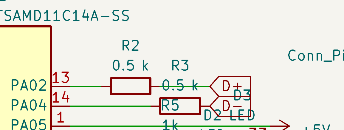
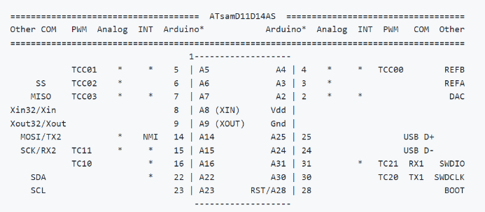
In the first case I used the microcontroller ATSAMD11D14U with the pin map:
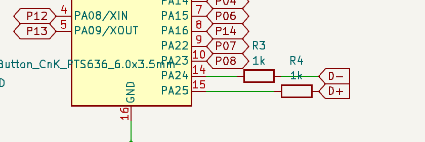
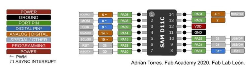
In the second case it was the microcontroller ATSAMD11C14U with the pin map:
By comparing my schematics with the pin maps, it’s easy to identify the mistakes I made.
I must admit that I underestimated the significance of this detail, and as a result, it played a decisive role in the problem.
A new PC(at)B is comming
For my new PCB I used the microcontroller ATSAMD11C14U as in my last one.
This time I checked carefully the pinouts and made a schematic:
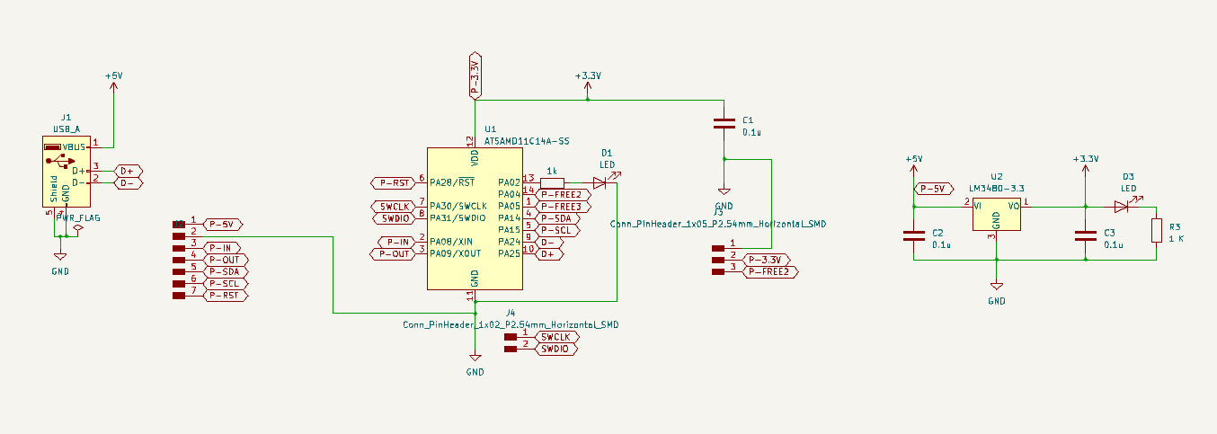
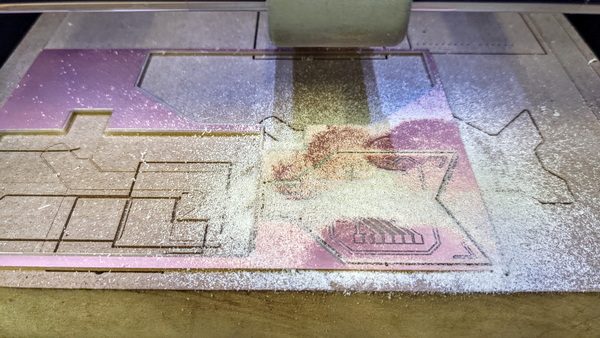
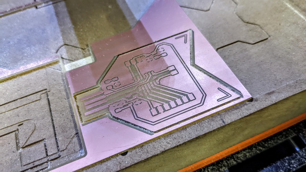
Here is the PCB design… now you understand why I call it PC(at)B

After was the milling, soldering and installation of bootloader. I repeated the board creation processes that are described in Electronics Production and Output Devices weeks documentation.
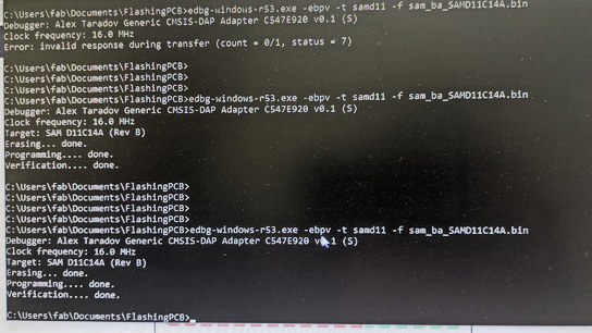
As you can notice during the bootloader installation process I had errors soldering-related: short circuits, after solving which I was able to install the bootloader.
To make sure the board is working properly, I made the lights on my new board blink.
I2C connection
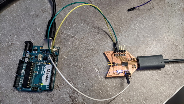
I decided to connect my PCB to the Arduino and try the I2C connection.
I2C, which stands for Inter-integrated circuit communication protocol, is a widely-used 2-wire serial communication protocol that is commonly used in embedded projects. It is designed for short-range data transfer applications and is used to interface with I2C-based sensors, digit displays, and communication modules. The protocol is ideal for projects that require communication between multiple devices.
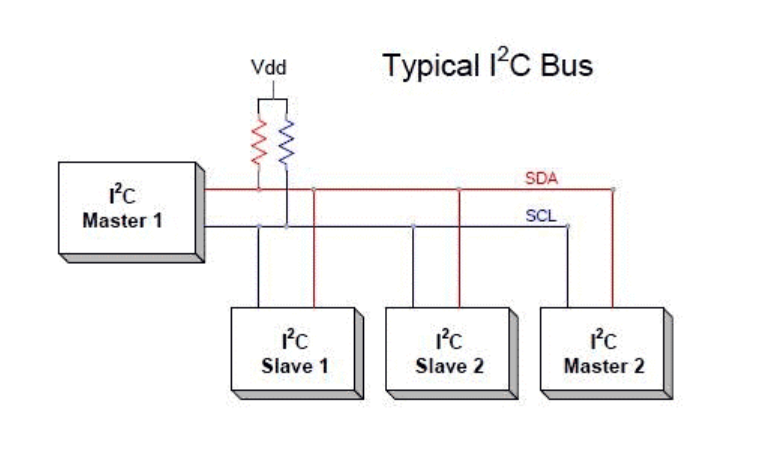
Devices that communicate using I2C connect through an I2C bus. This bus supports multiple Secondary and multiple Primary devices, making it a versatile communication protocol. Many sensors use I2C to transfer data to microcontrollers, while Secondary circuits can communicate with Primary circuits through this protocol. However, it should be noted that I2C is only suitable for short-distance data transmission.
The I2C protocol uses only two wires to carry out communication: SCL and SDA. SCL, or serial clock line, synchronizes the transmission of data between devices, while SDA, or serial data, carries the actual data to be transmitted. These lines are open-drain lines and require pull-up resistors to be connected if devices are active low. Each Secondary device connected to the bus has a unique 8-bit address that is used to enable the Primary device to send information to a specific Secondary device on the bus.
The communication between specific devices using two wires is achieved by giving each device its own unique device ID or address. The Primary device can then choose any specific device to communicate with using this address. I2C is designed to support both Primary and Secondary devices. Primary devices can send and receive information, while Secondary devices react to whatever the Primary sends. However, when sending information on the bus, only a single device can send information at a time. In summary, I2C allows for data transfer or communication with different numbers of devices using only two wires, which is particularly useful when working with microcontrollers that have a limited number of pins. The only drawback is that the protocol is not suitable for long-distance data transmission.
To learn more about establishing an I2C connection and connecting two Arduino boards, you may want to read this informative article.
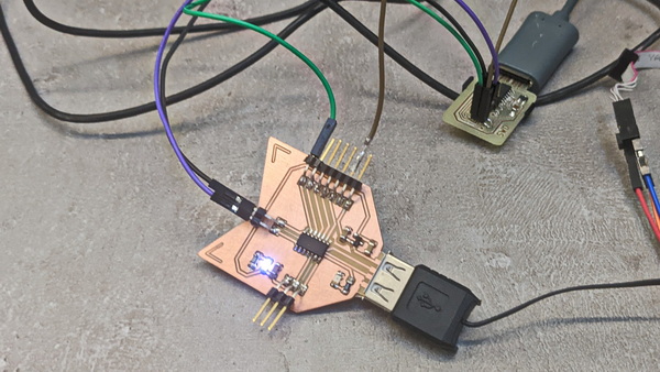
Now let’s try to connect my board to the Arduino:
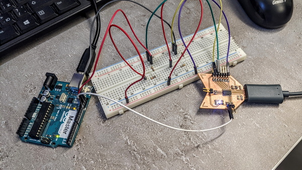
You ask me “why complicate everything using a brainboard?”. In fact, the connections have become easier than I imagined. But for beggining, in order not to damage the port and have a stable connection, I used the bradboard set up by Maxime using Pull-up Resistors.
After I discover, that:
In electronic logic circuits, a pull-up resistor (PU) or pull-down resistor (PD) is a resistor used to ensure a known state for a signal. It is typically used in combination with components such as switches and transistors, which physically interrupt the connection of subsequent components to ground or to VCC.
Also Google told me that:
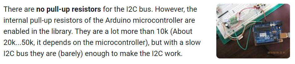
So in my case it didn’t make sense to use a breadboard and it was possible to connect my board with Arduino in a direct way.
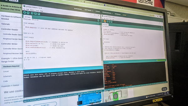
To check the I2C connection, I found a simple code for the Primary and Secondary.
For the Primary (Arduino) here:
// Wire Primary Writer
// by Nicholas Zambetti <http://www.zambetti.com>

// Demonstrates use of the Wire library
// Writes data to an I2C/TWI Peripheral device
// Refer to the "Wire Peripheral Receiver" example for use with this

// Created 29 March 2006

// This example code is in the public domain.


#include <Wire.h>

void setup()
{
  Wire.begin(); // join i2c bus (address optional for Primary)
}

byte x = 0;

void loop()
{
  Wire.beginTransmission(4); // transmit to device #4
  Wire.write("x is ");        // sends five bytes
  Wire.write(x);              // sends one byte
  Wire.endTransmission();    // stop transmitting

  x++;
  delay(500);
}
For the Secondary (my PCB) here:
// Wire Peripheral Receiver
// by Nicholas Zambetti <http://www.zambetti.com>

// Demonstrates use of the Wire library
// Receives data as an I2C/TWI Peripheral device
// Refer to the "Wire Primary Writer" example for use with this

// Created 29 March 2006

// This example code is in the public domain.


#include <Wire.h>

void setup()
{
  Wire.begin(4);                // join i2c bus with address #4
  Wire.onReceive(receiveEvent); // register event
  Serial.begin(9600);           // start serial for output
}

void loop()
{
  delay(100);
}

// function that executes whenever data is received from Primary
// this function is registered as an event, see setup()
void receiveEvent(int howMany)
{
  while(1 < Wire.available()) // loop through all but the last
  {
    char c = Wire.read(); // receive byte as a character
    Serial.print(c);         // print the character
  }
  int x = Wire.read();    // receive byte as an integer
  Serial.println(x);         // print the integer
}
In the case of unsigned integers, where only non-negative values are considered, the maximum value that can be represented with 1 byte is 255. This is because an 8-bit byte can represent 2^8 (256) unique combinations of bits, ranging from 0 to 255.
In the serial monitor, you can observe the changing numbers that increment by one every 0.1 second. The numbers continue to increase until they reach the value of 255, at which point the cycle restarts and the count begins again from zero.
Blinking the light on Secondary board (my PCB)
For my next experiment, I aimed to create a blinking light on my PCB. However, I wanted to implement an interesting approach to achieve this. My intention was to correlate the number displayed in the serial monitor with the number of blinks produced by the light. For example, if the serial monitor displayed the number one, the light would blink once, and for the number two, it would blink twice.
To avoid an excessive number of blinks, considering that the maximum value in the serial monitor is 255, I decided to limit the range of numbers. I increased the numbers incrementally, ensuring that the maximum value reached was 10. By doing so, I established a manageable range for the blinking pattern.
Code for Primary board (Arduino)
#include <Wire.h>

void setup()
{
  Wire.begin(); // join i2c bus (address optional for Primary)
}

byte x = 0;

void loop()
{
  Wire.beginTransmission(4); // transmit to device #4
  Wire.write("x is ");
  Wire.write(x);
  Wire.endTransmission();    // stop transmitting

  x++;
  delay(2000);

if (x == 10) {  //logical equal
x = 0;

  }
}
This code snippet utilizes the Wire library to establish I2C communication. It initializes the I2C bus in the setup() function and continuously sends data using the loop() function. The code transmits the string x is followed by the value of the variable x to my PCB with address 4. After each transmission, x is incremented and a delay of 2 seconds is introduced.
When x reaches a value of 10, it is reset to 0.
Code for Secondary board (my PCB)
#include <Wire.h>

void setup()
{
  pinMode (2, OUTPUT);
  Wire.begin(4);                // join i2c bus with address
   #4
  Wire.onReceive(receiveEvent); //
  Serial.begin(9600);           // start serial for output
}

void loop()
{
  delay(100);
}

// function that executes whenever data is received from Primary

{
  while (1 < Wire.available()) // loop through all but the last
  {
    char c = Wire.read(); // receive byte as a character
    Serial.print(c);         // print the character
  }
  int x = Wire.read();    // receive byte as an integer
  Serial.println(x);         // print the integer

  for (int i = 0; i < x; i++) {
    digitalWrite(2, HIGH);
    delay(100);
    digitalWrite(2, LOW);
    delay(100);
  }
}
When you receive a byte as a character, it means that the byte is treated as a character value based on a specific character encoding, such as ASCII or Unicode. The byte is interpreted as representing a particular character from the character set. The character can be a letter, digit, punctuation mark, or any other symbol defined in the character encoding standard.
When you receive a byte as an integer, the byte is treated as a numerical value rather than a character. Instead of interpreting the byte as a character from a character set, it is considered as a numeric value that can range from 0 to 255 (assuming an 8-bit byte). The byte represents an unsigned integer value within this range.
Raindrop Sensor and Servo Motor can become friends
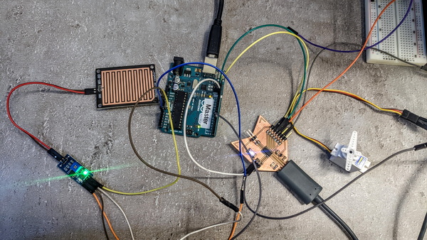
My latest idea involved connecting a rain sensor to a servo motor. The concept was to have the Arduino receive data from the rain sensor and then transmit that data to my PCB. Once the board received the data, it would activate the servo motor based on the information received.
By integrating the rain sensor with the servo motor, I aimed to create a dynamic mechanism that would respond to the changing weather conditions. When rain was detected, the servo motor could be programmed to adjust its position or perform a specific action, such as closing a shelter or adjusting the angle of a surface.
This project demonstrated the potential for using sensor data to drive specific actions or behaviors, allowing for automation and adaptation in response to environmental factors. By combining different components and utilizing the capabilities of the Arduino and my PCB, I could create an intelligent system that interacted with its surroundings based on real-time sensor input.
The Rain Sensor
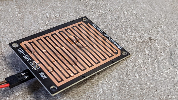
About the Rain Sensor
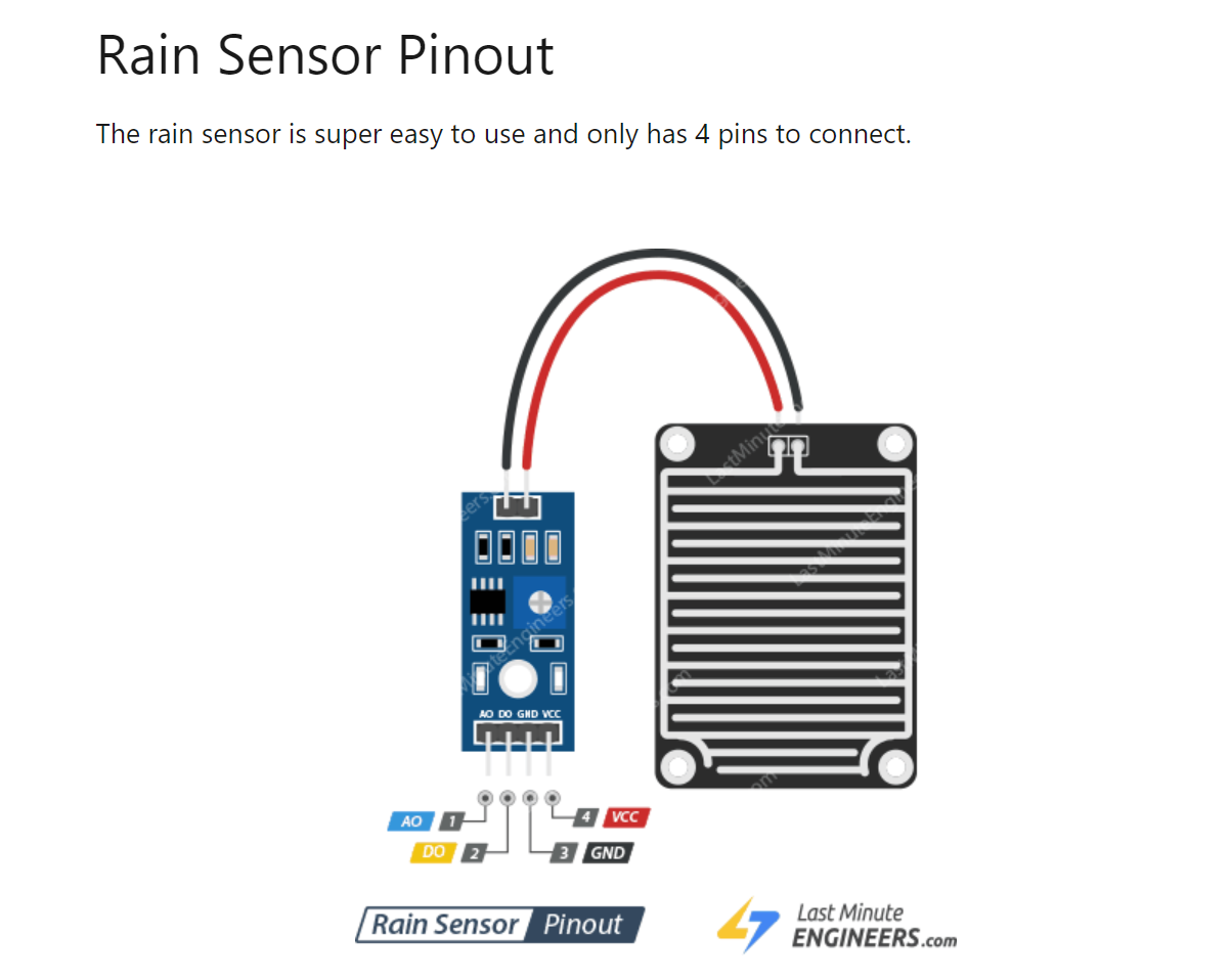
I connected the rain sencor to the Arduino. I chose the pin 8 as Digital Output.
I found the code in this video:
The reason I prefer this code is that it allows me to observe both analog and digital measurements at the same time, providing me with a more comprehensive understanding of the data.
int sensorAnalogPin = A0;
int sensorDigitalPin = 8;

int sensorAnalogValue = 0;
int sensorDigitalValue = 0;

void setup() {

  Serial.begin(9600);
  pinMode(sensorDigitalPin, INPUT);
}

void loop() {

 sensorAnalogValue = analogRead(sensorAnalogPin);
 sensorDigitalValue = digitalRead(sensorDigitalPin);

 Serial.print("Analog: ");
 Serial.println(sensorAnalogValue);
 Serial.print("Digital: ");
 Serial.println(sensorDigitalValue);
 Serial.print("");
 delay(1000);
}
The Servo Motor
In my Output Devices week documentation you can find the code to make working the servo motor.
Connection
Now it’s time to connect the Raindrop sensor and the Servo motor in one project.
I took the code for the sensor and changed it for the Primary board:
#include <Wire.h>

int sensorAnalogPin = A0;
int sensorDigitalPin = 8;

int sensorAnalogValue = 0;
int sensorDigitalValue = 0;

void setup() {
  Wire.begin(); // join i2c bus
  Serial.begin(9600);
}

void loop() {
  sensorAnalogValue = analogRead(sensorAnalogPin);
  sensorDigitalValue = digitalRead(sensorDigitalPin);

  uint8_t mappedNumber = map(sensorAnalogValue, 0, 1023, 0, 255);

  Wire.beginTransmission(5); // transmit to Secondary device #5
  Wire.write(mappedNumber);  // send mapped number
  Wire.write(sensorDigitalValue);  // send digital value
  Wire.endTransmission();    // stop transmitting

  Serial.print("Analog: ");
  Serial.println(mappedNumber);
  Serial.print("Digital: ");
  Serial.println(sensorDigitalValue);
  Serial.print("");

  delay(1000);
}
The program reads analog and digital sensor values, maps the analog value to a new range using map(), and transmits the mapped analog value and the digital value to a secondary device via I2C. The map() function takes an input value, the original input range, and the desired output range, and linearly scales the input value to the corresponding value in the new range.
I addes the map() function in this code which allows for efficient storage and representation of data within a single byte. By mapping the analog sensor value from a range of 0-1023 to a new range of 0-255, the resulting value can be stored in an unsigned 8-bit integer (uint8_t). This is advantageous in situations where limited storage space is a concern.
Code for Secondary board for servo motor:
#include <Wire.h>

#define SERVO_PIN 4

uint8_t analogValue = 0;
uint8_t digitalValue = 0;

void setup() {
  Wire.begin(5); // join I2C bus with address #5
  Wire.onReceive(receiveEvent); // register receive event
  pinMode(SERVO_PIN, OUTPUT); // set servo pin as output
  digitalWrite(SERVO_PIN, LOW); // ensure servo is initially off
}

void loop() {
  delay(100); // add some delay
}

void receiveEvent(int bytes) {
  while (Wire.available()) {
    analogValue = Wire.read();
    digitalValue = Wire.read();
  }
  Serial.print("Analog: ");
  Serial.println(analogValue);
  Serial.print("Digital: ");
  Serial.println(digitalValue);

  if (digitalValue == 0) {
    digitalWrite(SERVO_PIN, HIGH); // turn on servo
    for (int i = 0; i <= 90; i++) {
      delay(15);
      analogWrite(SERVO_PIN, i);
    }
    digitalWrite(SERVO_PIN, LOW); // turn off servo
  } else if (digitalValue == 1) {
    digitalWrite(SERVO_PIN, LOW); // turn off servo
  }
}
Within the loop() function, a small delay of 0.1 second is added to provide a delay between iterations.
The receiveEvent() function is called when data is received via I2C. It reads the analog and digital values sent from the primary device. The received analog and digital values are then printed to the Serial monitor.
If the received digital value is 0, the servo pin is set to a high state to turn on the servo. The code then gradually increases the analog value from 0 to 90 using analogWrite() to control the servo’s position. Finally, the servo pin is set to a low state to turn off the servo.
If the received digital value is 1, the servo pin is simply set to a low state, turning off the servo motor.
When I submerged the rain sensor into a glass of water, I observed that the digital value output by the sensor became 0. This change in value triggered a response in the system, causing the servo motor to start moving.
This experiment showcased the direct correlation between the sensor input and the resulting action of the servo motor. It demonstrated the system’s ability to respond to environmental conditions and perform a specific task, such as initiating the movement of the servo motor.
Conclusion
The past week has been incredibly exciting for me as I delved into the realm of communication between two boards. Witnessing the interaction and exchange of data between these boards was a fascinating experience. During my programming sessions, I explored a novel approach that involved assigning “addresses” to each PCB.
I had the opportunity to explore the Map function, which proved to be an invaluable tool for precise data manipulation.
Overall, this week was a significant milestone in my programming journey. I took several steps forward, expanding my knowledge and skills in the world of programming.
Original Files
PCB Schematic and Design (KiCAD)