Output Devices
Preparation process and programming
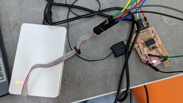
I started my week by programming my board. It’s very exciting when your creation starts to work. To do this, I need a programmer to load the bootloader into my board and get it ready for programming via USB. And in this beautiful moment, I discovered that I did not foresee that I would need a reset pin. And at the suggestion of my instructor, I added a single pin directly to the ready-made plate, gradually turning it into Frankenstein. You can watch the process of my PCB fabrication in my documentation of the week Electronics Production.
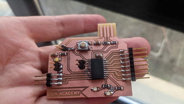
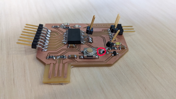
In fact, this small transformation did not interfere with the functioning of my board in any way.
EDGB install
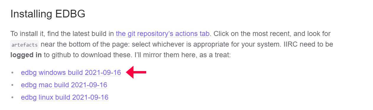
To load the bootloader into the board, we need to install The Atmel® Embedded Debugger (EDBG) - an onboard debugger for integration into development kits with Atmel MCUs. “In addition to programming and debugging support through Atmel Studio, the EDBG offers data streaming capabilities between the host computer and the target MCU.” You can find out more about EDBG here
To install EDGB, I selected the relevant link from the EDGB guide page. Since the operating system on my computer is Windows, I chose the following link.
Bootloader install
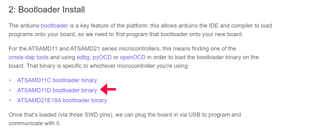
Now we need to install the bootloader. I found the description and the .bin file I need in Fab Arduino SAM Guide
(There I also found details on how to set up Arduino in order to write code for my own board. But more on that later.)
Here I have selected the option that is intended for my board with microcontroller ATSAMD11D14A-SS.
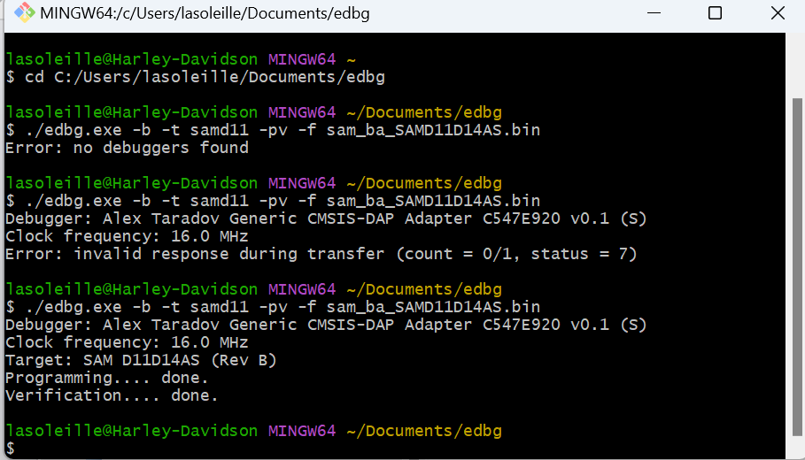
Now we need to collect edgb.exe and sam_ba_SAMD11D14AS.bin them in one folder. Here we run the GitBash. Writing the command:
$ ./edbg.exe -b -t samd11 -pv -f sam_ba_SAMD11D14AS.bin
The last part of the command is the name of our .bin file.
Now we can abandon the programmer and move on to board programming via USB.
Arduino setup
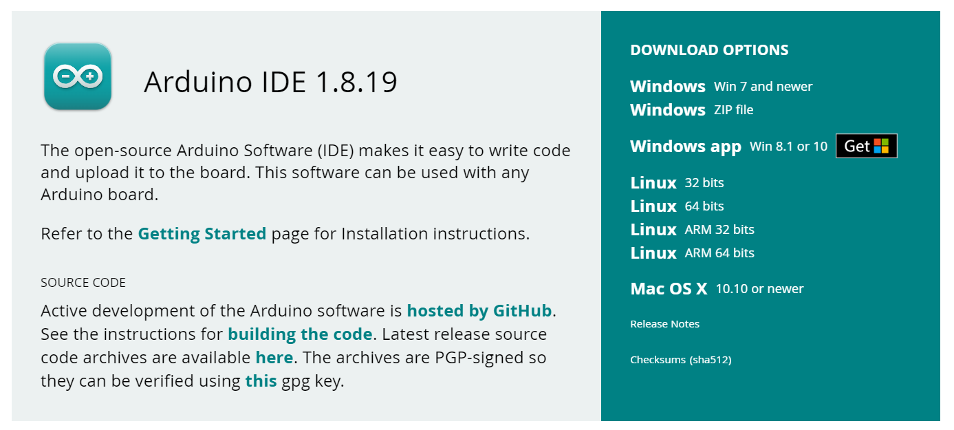
In order to be able to program the board, I used the Arduino software, but I needed an old version of the program, so I went to the software site again.
To set up the program I started following the step by step instructions in this document.
- file -> preferences -> additional board manager URLS
add this link: *https://raw.githubusercontent.com/qbolsee/ArduinoCore-fab-sam/master/json/package_Fab_SAM_index.json*
now arduino will be able to find the “board definitions” when we do:
- tools -> board -> board manager
search for Fab SAM core for Arduino
hit install
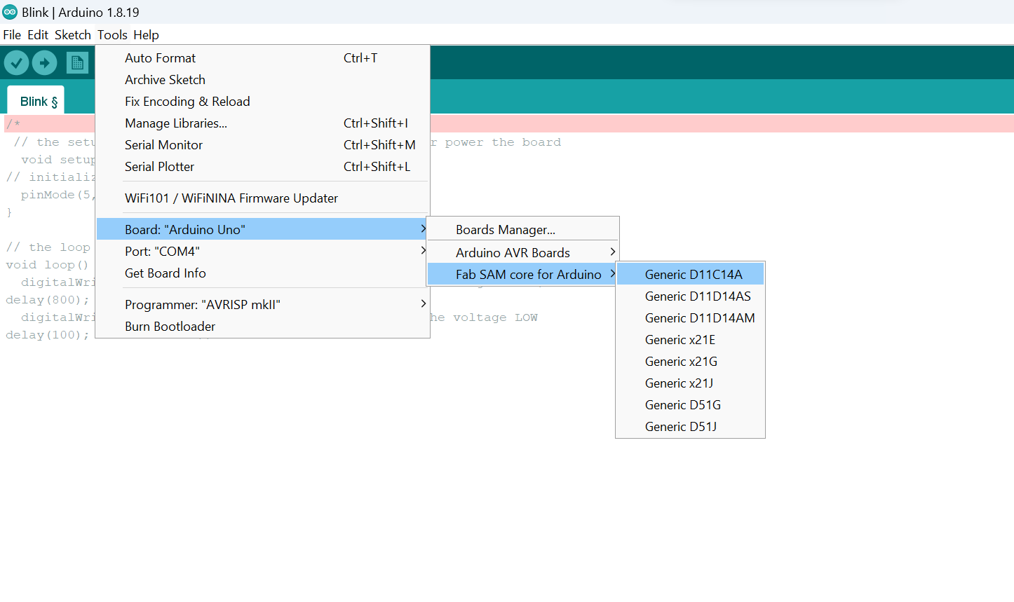
After that I chose my microcontroller from the list
Programming
On my board I have 3 LED lights - one for power, two to program. And I wanted to start playing with them. I decided to start simple - make the light blink. To do this, I used the code that I came up with in the Embedded Programming week, changing the timing a bit.
// the setup function runs once when you press reset or power the board
  void setup() {
// initialize digital pin 13 as an output.
  pinMode(13,OUTPUT);
}

// the loop function runs over and over again forever
void loop() {
  digitalWrite(6,HIGH); // turn the LED on (HIGH is the voltage level)
delay(800);              // wait for 0.8 second
  digitalWrite(6,LOW);  // turn the LED off by making the voltage LOW
delay(800);              // wait for 0.8 second
}
How did I know which number corresponds to the light pin on my microcontroller? I used the pin map I found here.
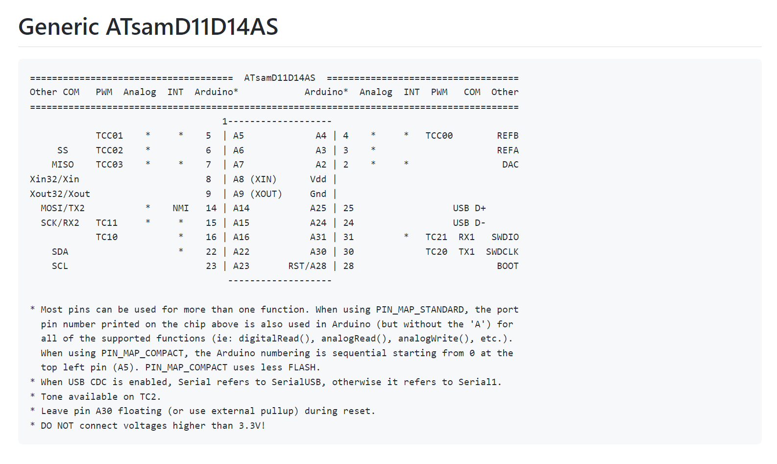
In this case, the 2 LEDs that I can program correspond to the numbers 5 and 6 in the Arduino.
Looking at this little light was happiness!!
But what is the use of two LEDs if only one of them is flashing?! I needed a code that made 2 lights blink.
So I asked my “friend” Chat GPT for little help:
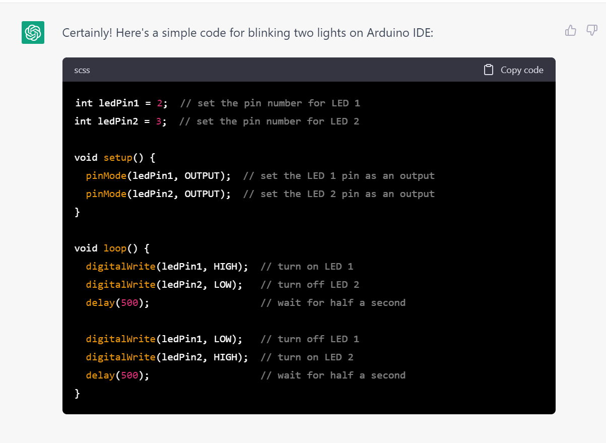
Here I have the universal code and I need to replace 2 and 3 by 5 and 6.
int ledPin1 = 5;  // set the pin number for LED 1
int ledPin2 = 6;  // set the pin number for LED 2

void setup() {
  pinMode(ledPin1, OUTPUT);  // set the LED 1 pin as an output
  pinMode(ledPin2, OUTPUT);  // set the LED 2 pin as an output
}

void loop() {
  digitalWrite(ledPin1, HIGH);  // turn on LED 1
  digitalWrite(ledPin2, LOW);   // turn off LED 2
  delay(500);                   // wait for half a second

  digitalWrite(ledPin1, LOW);   // turn off LED 1
  digitalWrite(ledPin2, HIGH);  // turn on LED 2
  delay(500);                   // wait for half a second
}
I also played with timing and the night show is ready! :)
Time For Output Device
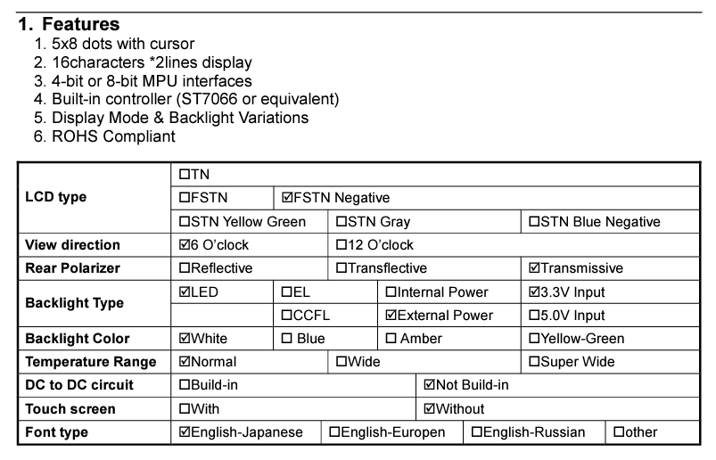
LCD 16x2
Now it’s time for my PCB to facilitate the functionality of another device. To accomplish this, I have decided to connect an LCD to it.
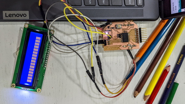
From the datasheet I started to explore the datasheet to get more information about this device.
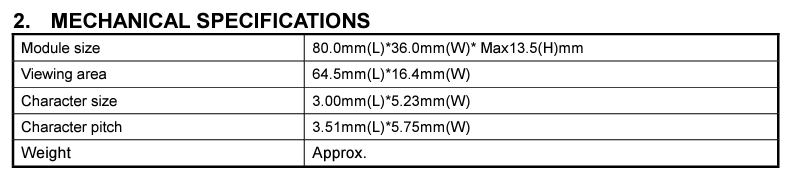
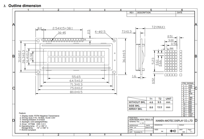
The LCD in our Fab Lab comes with an integrated I2C module.
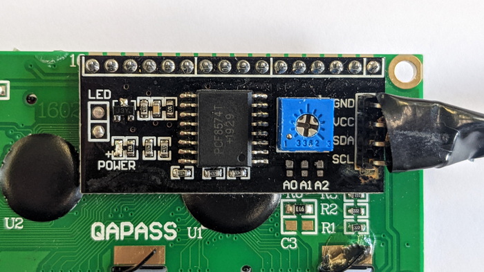
The I2C backpack or controller acts as an interface between the microcontroller and the LCD, handling the low-level communication details. It takes care of generating the necessary signals to send data and commands to the LCD and receive responses from it. By using an I2C module, the number of pins required for the connection is reduced, simplifying the hardware setup and allowing for more efficient use of available I/O pins on the microcontroller.
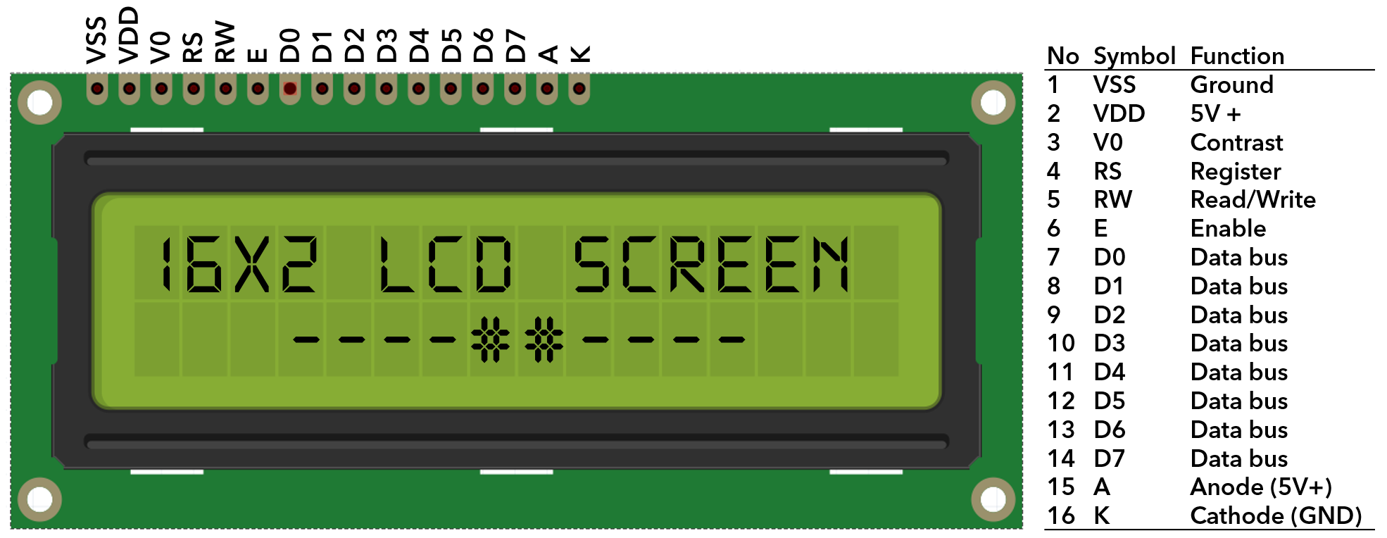
When connecting an LCD to an I2C module, the pin distribution typically involves a much simpler interface. The I2C module utilizes a standard 4-pin interface, commonly known as the I2C or IIC (Inter-Integrated Circuit) interface. The pin distribution for this configuration is as follows:
- VCC: This pin is connected to the power supply, providing the required voltage for the LCD module.
- GND: This pin is connected to the ground or 0V reference.
- SDA: The Serial Data Line (SDA) is responsible for bidirectional data transfer between the I2C module and the LCD.
- SCL: The Serial Clock Line (SCL) provides the clock signal for synchronizing data transfer between the I2C module and the LCD.
I took the code from my Embedded Programming week documentation.
#include <Wire.h>
#include <LiquidCrystal_I2C.h>

// Set the address of the LCD
const uint8_t LCD_ADDR = 0x27;

// Set the number of columns and rows on the LCD
const uint8_t LCD_COLS = 16;
const uint8_t LCD_ROWS = 2;

// Create an instance of the LiquidCrystal_I2C class
LiquidCrystal_I2C lcd(LCD_ADDR, LCD_COLS, LCD_ROWS);

void setup() {
  // Initialize the I2C communication
  Wire.begin();

  // Initialize the LCD
  lcd.init();

  // Turn on the backlight
  lcd.backlight();

  // Print a message to the LCD
  lcd.print("Hello, World!");
}

void loop() {
  // Do nothing
}
The first obstacle I encountered was the message.
WARNING: library LiquidCrystal_I2C claims to run on avr architecture(s) and may be incompatible with your current board which runs on samd architecture(s).
Of course, it didn’t work and I didn’t see anything on the glowing screen. I started looking for libraries with SAMD architecture. And I came across a very interesting list of libraries, which you will find here.
Here I found only 2 libraries that are marked that they will probably help in programming my LCD:
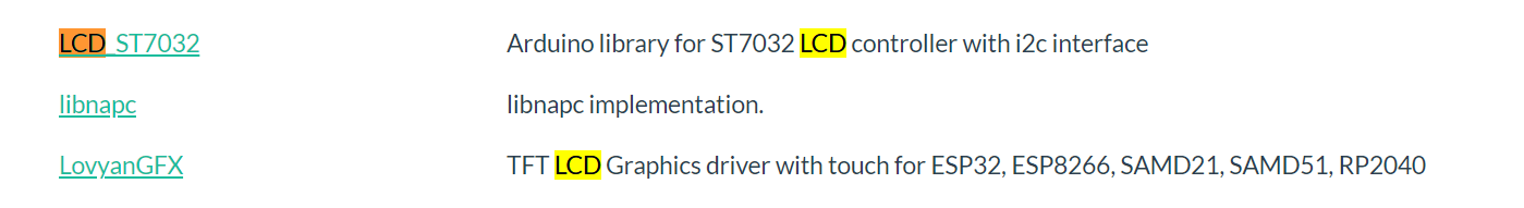
Unfortunately, the use of none of these libraries did not give any result.
Code exemple by Chat GPT to connect an LCD to SAMD11D using I2C communication using the library LCD_ST7032
#include <Wire.h>
#include <LCD_ST7032.h>

// Initialize the LCD object with the I2C address
LCD_ST7032 lcd(0x3E);

void setup() {
  // Initialize I2C communication
  Wire.begin();

  // Initialize the LCD
  lcd.init();
  lcd.backlight();

  // Set the cursor to the first column, first row
  lcd.setCursor(0, 0);

  // Print a message on the LCD
  lcd.print("Hello, LCD!");
}

void loop() {
  // Code for your main program logic goes here
}
It didn’t work!!
To discover the address of my LCD, I used the code to activate the I2C scanner:
#include <Wire.h>

void setup() {
  Wire.begin();

  Serial.begin(9600);
  while (!Serial);

  Serial.println("\nI2C Scanner");
}

void loop() {
  byte error, address;
  int deviceCount = 0;

  Serial.println("Scanning...");

  for (address = 1; address < 127; ++address) {
    Wire.beginTransmission(address);
    error = Wire.endTransmission();

    if (error == 0) {
      Serial.print("Device found at address 0x");
      if (address < 16) {
        Serial.print("0");
      }
      Serial.print(address, HEX);
      Serial.println();

      deviceCount++;
    }
  }

  if (deviceCount == 0) {
    Serial.println("No devices found.");
  }

  delay(5000);
}
On the serial monitor I got the message:
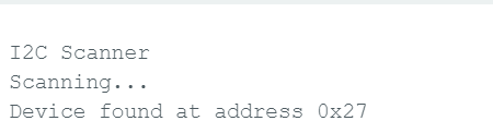
So I changed the address in my previous code:
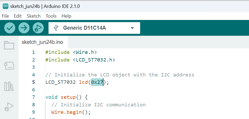
I hade the error message:
exit status 1
Compilation error: no matching function for call to ‘LCD_ST7032::LCD_ST7032(int)’
It seems that the “LCD_ST7032” library doesn’t provide a constructor that takes an integer argument for the I2C address.
I asked for another code without LCD_ST7032 library: here what I got:
#include <Arduino.h>
#include <Wire.h>

// Define LCD I2C address
const byte LCD_ADDRESS = 0x27;

// Define LCD commands
const byte LCD_COMMAND_INIT = 0x00;   // Initialization command
const byte LCD_COMMAND_DISPLAY_ON = 0x0C;   // Display on command
const byte LCD_COMMAND_CLEAR = 0x01;   // Clear display command

// Function to send a command to the LCD
void lcdCommand(byte command) {
  Wire.beginTransmission(LCD_ADDRESS);
  Wire.write(0x00);  // Control byte for command
  Wire.write(command);
  Wire.endTransmission();
  delay(2);  // Delay for stability
}

// Function to send data to the LCD
void lcdWrite(byte data) {
  Wire.beginTransmission(LCD_ADDRESS);
  Wire.write(0x80);  // Control byte for data
  Wire.write(data);
  Wire.endTransmission();
  delayMicroseconds(50);  // Delay for stability
}

// Function to initialize the LCD
void lcdInit() {
  Wire.begin();
  delay(50);  // Delay for stability

  // Initialization sequence
  lcdCommand(LCD_COMMAND_INIT);
  delay(5);

  lcdCommand(LCD_COMMAND_DISPLAY_ON);
  delay(5);

  lcdCommand(LCD_COMMAND_CLEAR);
  delay(5);
}

void setup() {
  lcdInit();

  // Set cursor to the first column, first row
  lcdCommand(0x80);

  // Print a message on the LCD
  lcdWrite('H');
  lcdWrite('e');
  lcdWrite('l');
  lcdWrite('l');
  lcdWrite('o');
  lcdWrite(',');
  lcdWrite(' ');
  lcdWrite('L');
  lcdWrite('C');
  lcdWrite('D');
}

void loop() {
  // Your code here
}
I made changes to the code based on the datasheet of my LCD. To better understand the underlying logic, I came across an interesting video that helped me establish the connection between the LCD parameters and coding. It was incredibly helpful in clarifying how to write the code effectively.
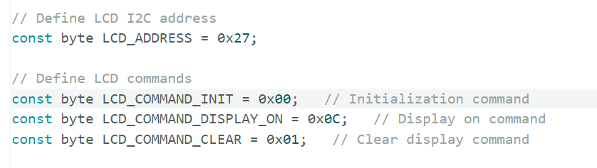
Here in the code, we have various commands that need to be compared with the datasheet. As mentioned earlier, the most crucial one is the LCD_ADDRESS, which can be found in the datasheet.
So the address will be 0x27.
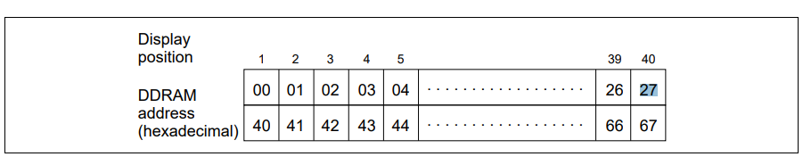
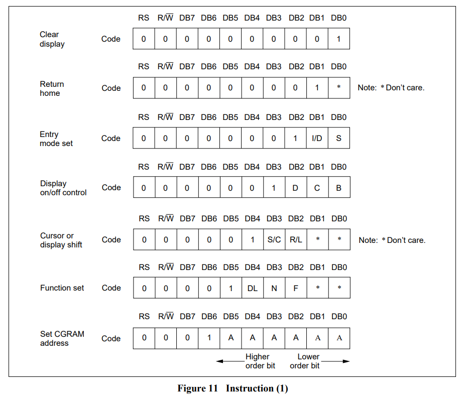
The HD44780 controller uses an 8-bit instruction set. The most significant 4 bits of the command represent the instruction code, while the least significant 4 bits (often referred to as “Nibble”) can be used for additional data or parameters associated with the command.
However, when using the LCD module in 4-bit mode (which is common), the commands are sent in two separate 4-bit nibbles to save pins on the microcontroller. The first nibble contains the most significant bits of the instruction, and the second nibble contains the least significant bits or data.
For example, the command to clear the display is represented by the instruction code 0x01. In 8-bit mode, you would send 0x01 as a complete byte. But in 4-bit mode, you send the two nibbles separately: first 0x0 and then 0x1.
Useful information
During my research on libraries, I came across some information that you might find useful. I already knew how to install libraries on Arduino, but didn’t know how to remove them. You can do this easily by going to Files -> Preferences, copying the Sketchbook location (this is the directory where all your Arduino files are stored).
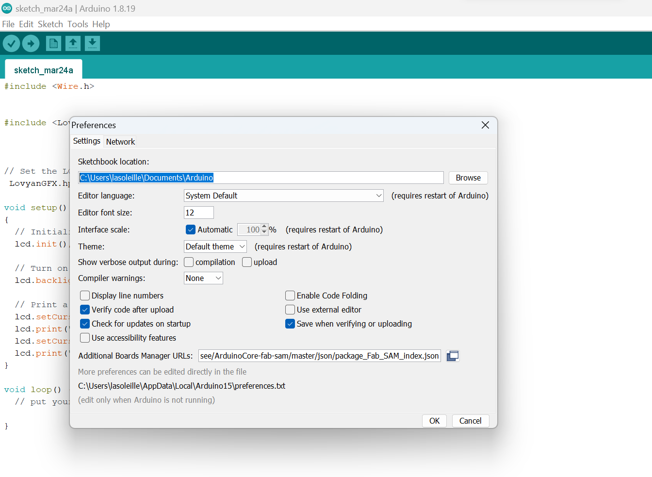
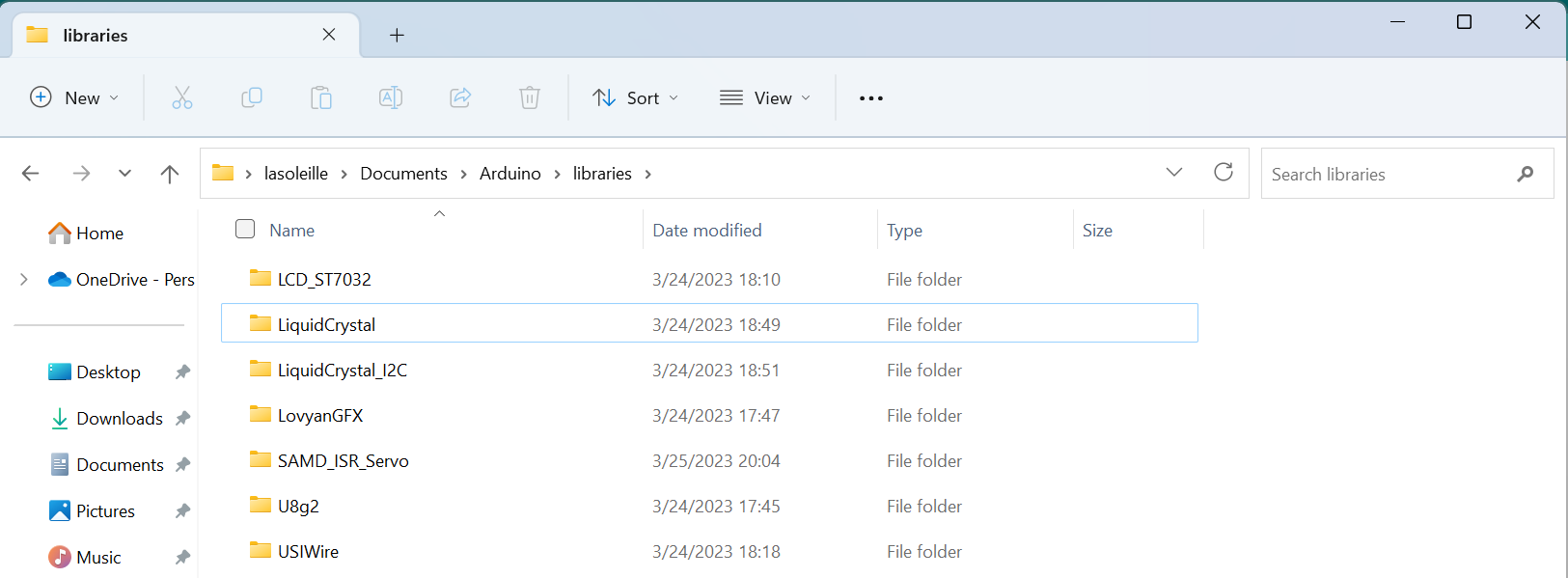
Then we need to find the same directory on your computer, and voila! where you need it. Open the “Libraries” folder and delete the folder with the name of the library you want to delete. This library will never “interfere” with us again.
Without USB
After all the hard drinking, my PCB’s USB decided to give up completely and stopped showing up to my computer. With the joint efforts of my instructor Babken Chugaszyan, we tried to bring him back to life, but we never managed to do it. Since there was a little time and I did not have time to create a new board, Babken advised me to switch to “manual control” and program the output device without using USB - with the help of a programmer.
For this, I decided to use Atmel ICE programmer, thinking that it would make my work with Arduino software easier (but I was wrong).
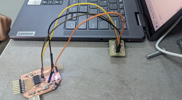
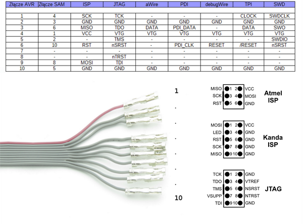
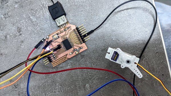
To connect the programmer to the PCB, I used this scheme:
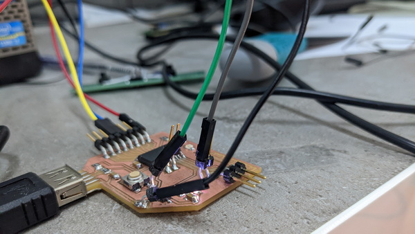
My PCB looked like a real Christmas tree:
After a little tinkering with this programmer, I realized that there is another problem: to connect this programmer, I needed to occupy the VCC pin on my PCB. And I need the same pin to connect the output device. So I had to make a choice in favor of another programmer, created in the Fab Lab, since he connected to the power source via USB.
After this connection, I decided to run the blinking light program again and it worked!! I realized that I was on the right track.
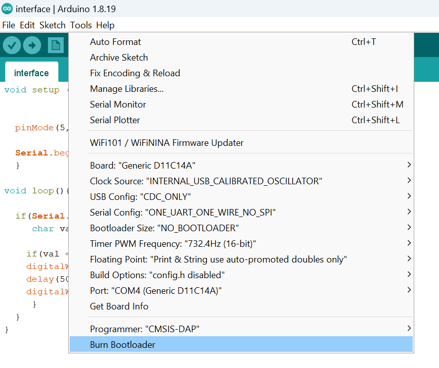
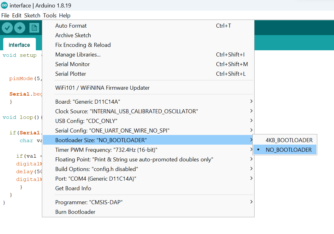
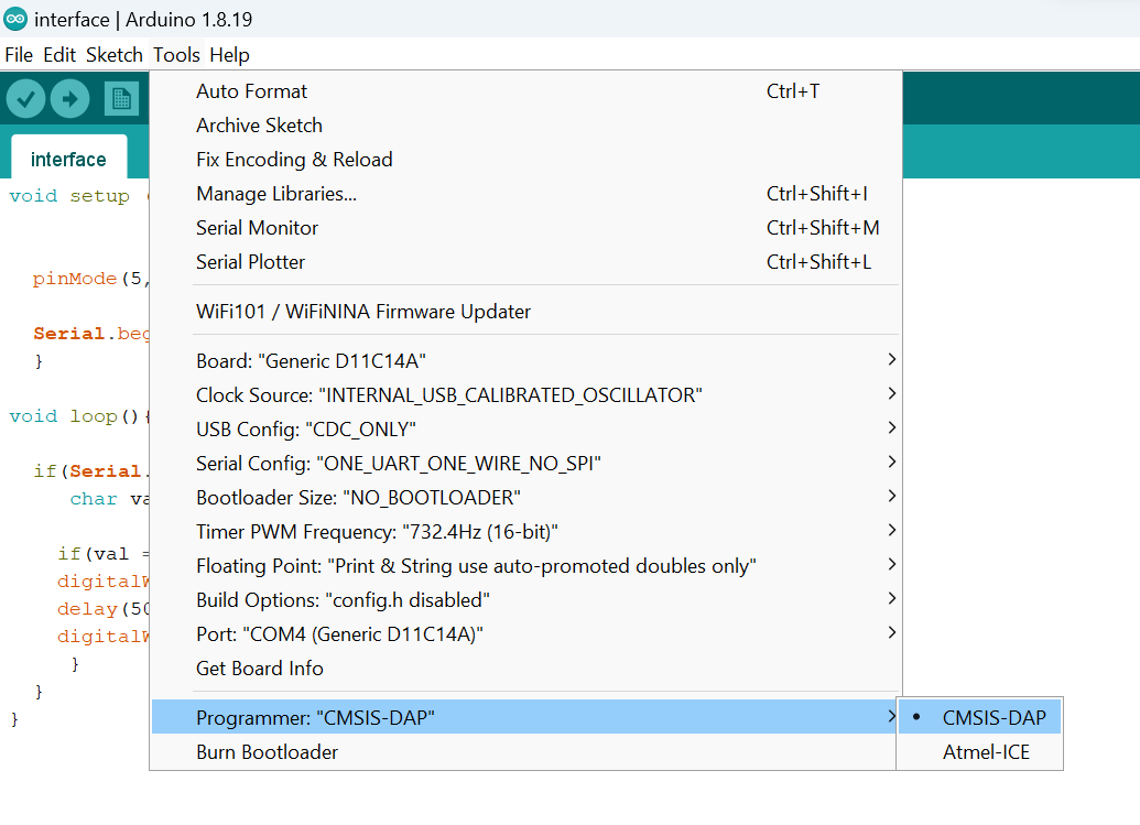
Arduino setup:
To run the code using a Programmer, we need to make some changes in the Tool menu of Arduino. Please follow these steps:
Servo motor
I also decided to work with another output device - I connected a servo motor and hoped that it would work after all my efforts.
-
Brushed servo motors: Commutation through brushes and a commutator, resulting in more friction, brush wear, and electrical noise. Lower efficiency, higher maintenance needs, and limited reliability.
-
Brushless servo motors: Electronic commutation without brushes. Higher efficiency, longer lifespan, smoother operation, reduced maintenance. Costlier but cost-effective for demanding applications.
The pinout for a servo motor:
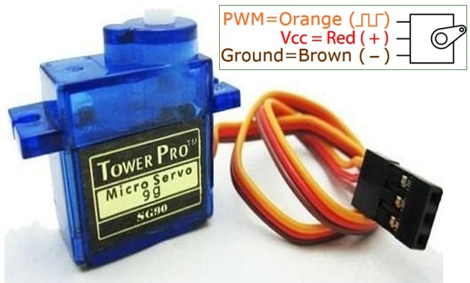
I connected the orange wire to my output pin, which according to the pin map is number 9 in the Arduino.
I needed a code to turn on the servo without using libraries, which was kindly provided to me by chat GPT:
#define SERVO_PIN 0            // define the pin number for the servo
#define SERVO_MIN_ANGLE 0      // define the minimum angle for the servo (in degrees)
#define SERVO_MAX_ANGLE 180    // define the maximum angle for the servo (in degrees)
#define SERVO_MIN_PULSE 500    // define the minimum pulse width for the servo (in microseconds)
#define SERVO_MAX_PULSE 2500   // define the maximum pulse width for the servo (in microseconds)
#define SERVO_UPDATE_TIME 20   // define the update time for the servo (in milliseconds)

void setup() {
  pinMode(SERVO_PIN, OUTPUT); // set the pin for the servo as an output
}

void loop() {
  // move the servo to 0 degrees
  setServoAngle(SERVO_PIN, SERVO_MIN_ANGLE);
  delay(1000);

  // move the servo to 90 degrees
  setServoAngle(SERVO_PIN, (SERVO_MAX_ANGLE - SERVO_MIN_ANGLE) / 2 + SERVO_MIN_ANGLE);
  delay(1000);

  // move the servo to 180 degrees
  setServoAngle(SERVO_PIN, SERVO_MAX_ANGLE);
  delay(1000);
}

void setServoAngle(int pin, int angle) {
  int pulseWidth = map(angle, SERVO_MIN_ANGLE, SERVO_MAX_ANGLE, SERVO_MIN_PULSE, SERVO_MAX_PULSE);
  int pulseTime = pulseWidth / 1000;

  for (int i = 0; i < SERVO_UPDATE_TIME / pulseTime; i++) {
    digitalWrite(pin, HIGH);
    delayMicroseconds(pulseWidth);
    digitalWrite(pin, LOW);
    delay(SERVO_UPDATE_TIME - pulseTime);
  }
}
My joy knew no bounds when my motor head began to move.
After some changes, I got an interesting rhythm.
#define SERVO_PIN 9            // define the pin number for the servo
#define SERVO_MIN_ANGLE 90      // define the minimum angle for the servo (in degrees)
#define SERVO_MAX_ANGLE 180    // define the maximum angle for the servo (in degrees)
#define SERVO_MIN_PULSE 500    // define the minimum pulse width for the servo (in microseconds)
#define SERVO_MAX_PULSE 2500   // define the maximum pulse width for the servo (in microseconds)
#define SERVO_UPDATE_TIME 20   // define the update time for the servo (in milliseconds)

void setup() {
  pinMode(SERVO_PIN, OUTPUT); // set the pin for the servo as an output
}

void loop() {
  // move the servo to 0 degrees
  setServoAngle(SERVO_PIN, SERVO_MIN_ANGLE);
  delay(200);

  // move the servo to 90 degrees
  setServoAngle(SERVO_PIN, (SERVO_MAX_ANGLE - SERVO_MIN_ANGLE) / 2 + SERVO_MIN_ANGLE);
  delay(1200);

  // move the servo to 180 degrees
  setServoAngle(SERVO_PIN, SERVO_MAX_ANGLE);
  delay(1000);
}

void setServoAngle(int pin, int angle) {
  int pulseWidth = map(angle, SERVO_MIN_ANGLE, SERVO_MAX_ANGLE, SERVO_MIN_PULSE, SERVO_MAX_PULSE);
  int pulseTime = pulseWidth / 500;

  for (int i = 0; i < SERVO_UPDATE_TIME / pulseTime; i++) {
    digitalWrite(pin, HIGH);
    delayMicroseconds(pulseWidth);
    digitalWrite(pin, LOW);
    delay(SERVO_UPDATE_TIME - pulseTime);
  }
}
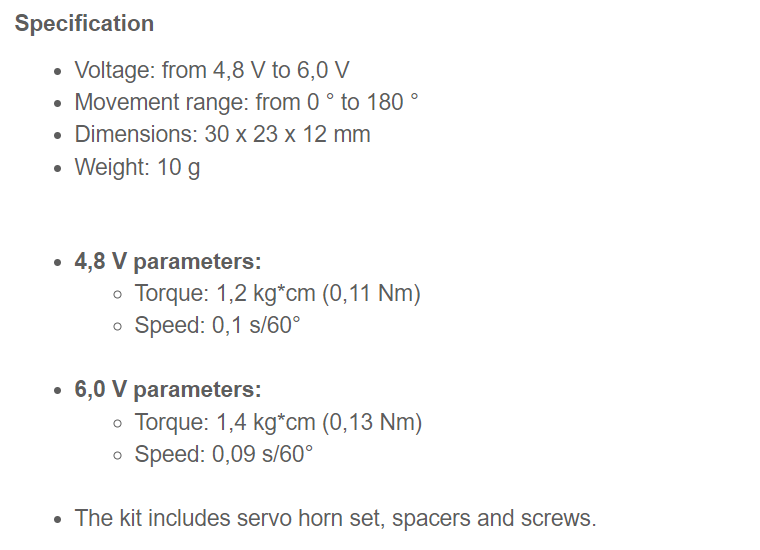
To match the servo motor specifications, I edited the code:
#define SERVO_PIN 0                  // define the pin number for the servo

const int servoMinAngle = 0;         // define the minimum angle for the servo (in degrees)
const int servoMaxAngle = 180;       // define the maximum angle for the servo (in degrees)
const int servoMinPulse = 500;       // define the minimum pulse width for the servo (in microseconds)
const int servoMaxPulse = 2500;      // define the maximum pulse width for the servo (in microseconds)
const int servoUpdateTime = 20;      // define the update time for the servo (in milliseconds)

void setup() {
  pinMode(SERVO_PIN, OUTPUT);        // set the pin for the servo as an output
}

void loop() {
  // move the servo to 0 degrees (4.8V)
  setServoAngle(0, 0.1);             // Angle: 0°, Speed: 0.1 s/60°
  delay(1000);

  // move the servo to 90 degrees (4.8V)
  setServoAngle(90, 0.1);            // Angle: 90°, Speed: 0.1 s/60°
  delay(1000);

  // move the servo to 180 degrees (6.0V)
  setServoAngle(180, 0.09);          // Angle: 180°, Speed: 0.09 s/60°
  delay(1000);
}

void setServoAngle(int angle, float speed) {
  int pulseWidth = map(angle, servoMinAngle, servoMaxAngle, servoMinPulse, servoMaxPulse);
  int pulseTime = pulseWidth * speed / 60;

  for (int i = 0; i < servoUpdateTime / pulseTime; i++) {
    digitalWrite(SERVO_PIN, HIGH);
    delayMicroseconds(pulseWidth);
    digitalWrite(SERVO_PIN, LOW);
    delay(servoUpdateTime - pulseTime);
  }
}
In this updated version, I added an additional parameter to the setServoAngle() function to represent the speed of movement. The speed parameter is given as a fraction of the specified speed (s/60°) in the servo specifications.
Within the loop() function each movement is achieved by calling the *setServoAngle() function with the desired angle and corresponding speed as arguments. The delays between movements are included to provide a pause between each position.
The setServoAngle() function maps the desired angle to a corresponding pulse width using the specified angle range and pulse width range. It calculates the pulse time based on the given speed (fraction of s/60°).
Within the for loop, the servo pin is set to HIGH, and the pulse width is maintained for the calculated pulse time using delayMicroseconds(). Then, the pin is set to LOW, and the remaining time until the total servoUpdateTime is reached is delayed.
Maybe on the next step I will attach the guitar pick to the motor and come up with a simple mechanism to attach my working servo motor to the guitar. Surprising… what kind of music will come out?!
What’s next?
- The first thing I need to do is keep experimenting and get the LCD to show me some text because I don’t like to stop half way.
- As I’ve already pointed out, it might be a good idea to attach a guitar pick to the motor and see what happens.
- I need to build and program an improved version of my PCB that will have a good connection via USB.
Post Scriptum: “Transforming from Frankenstein to the Prince”
Dealing with a cumbersome PCB can be quite challenging. However, I managed to rearrange all the pins and made revisions to the schematic and PCB design. Here is the resulting improved version:
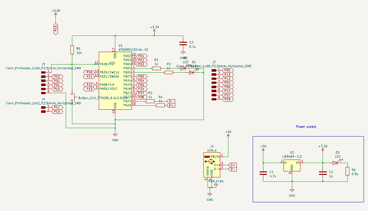
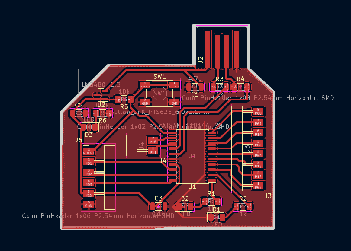
You can also download the edited version from the Original files section.
Group Assignment
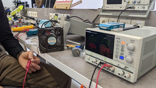
We had a great introduction to DC power supply and Digital Multimeters from our instructor Babken Chugaszyan. We were able to test the DC motor, a few meters of LED light and even a fan.
You can find out more about our group assignment here.
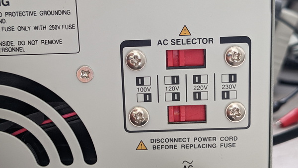
DC Power Supply
Interesting nuances that caught my attention during the group assignment: - I decided to do a little research on DC Power Supply and came across an interesting article. Here you can find out more about DC Power Supply
- As you can see, this is the other side of DC Power Supply. Here you can adjust the AC voltage to which this device is connected. We have several options to choose from, which is configured using switches. This is very important for the safe use of the device.
- Another important point for safety: you should always make sure that the “OUTPUT” button is disabled before connecting another device to the power supply.
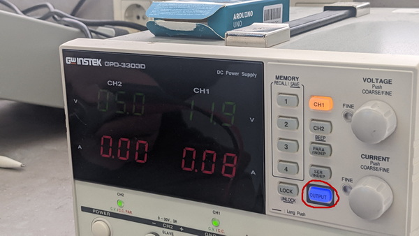
- By measuring the voltage and current strength of various devices, we again remembered Ohm’s law, where:
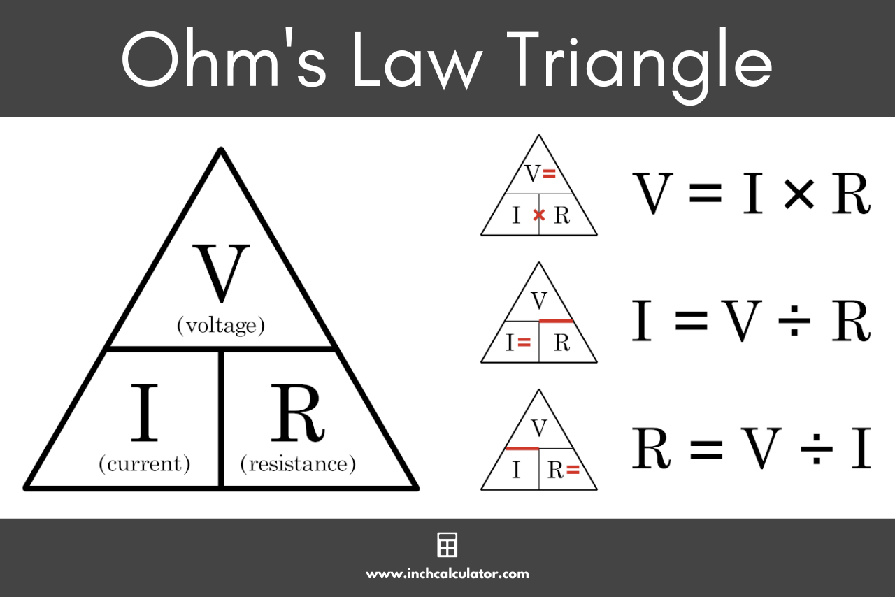
and
Therefore, if 2 of these parameters are indicated on the device, we can always easily calculate the third one.
- There is one more interesting detail: if we indicate the current strength is less than necessary, a red light is on on the power supply. Most AC-DC power supplies and DC-DC converters have internal current-limiting circuits to protect the power device, and to some degree its load.
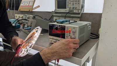
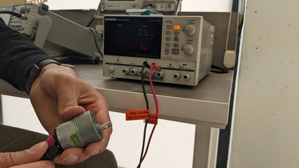
- What surprised me, and it was very interesting to observe that during the start of the work, the device uses the highest current. But if you create obstacles, the current strength can reach up to a value several times greater. Basically, on the device is indicated the current strength that is optimal for the normal operation of the device.
Digital Multimeter
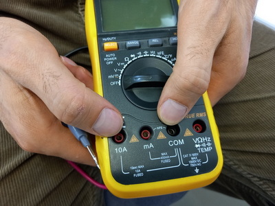
When I was building my PCB, I got to know Digital Multimeters (we call it a tester) to check the operation of the components on the board and see if there was a short circuit after soldering. A digital multimeter is a test tool used to measure two or more electrical values—principally voltage (volts), current (amps) and resistance (ohms). During my research, I came across a useful video where you can also learn more about Digital Multimeters
- Before starting to work with a multimeter, it is important to understand what exactly we want to measure: voltage, resistance, or do we want to check the connection and get a signal? You need to ask yourself this question in order to connect the multimeter correctly.
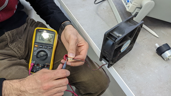
By measuring the resistance on different devices, and working with two devices, we were again convinced of the correctness of Ohm’s law.
This week has been an exciting journey through the world of electronics!
Original files
My first PCB
My first PCB - Edited