Input Devices
Task: Input Devices
Group assignment:
- Probe an input device(s)’s analog and digital signals
- Document your work on the group work page and reflect on your individual page what you learned
Individual assignment:
- Measure something: add a sensor to a microcontroller board that you have designed and read it.
Group assignment
I derive immense joy from learning every day, particularly when it comes to the boundless possibilities of sensors that can “feel” and accurately describe the world around us.
In a group setting, we had the opportunity to explore a range of sensors, including both analog and digital signals. You can find more abour our experiments in our Group Assignment page.
Personally, I found the Potentiometer to be a fascinating discovery. This is a simple, but smart “construction”:
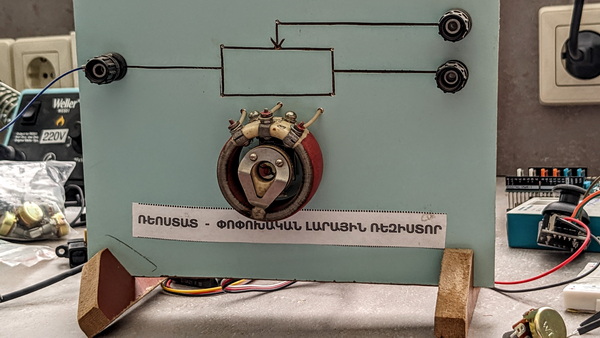
A potentiometer (a resistive sensor) is a type of resistor that can be manually adjusted and has three terminals. The first two terminals are connected to the two ends of a resistive element, while the third terminal is connected to a sliding contact known as a wiper that moves along the resistive element. The potentiometer can be thought of as a variable resistance divider that essentially splits the resistive element into two resistors in series. The position of the wiper determines the resistance ratio of the first resistor to the second resistor, which in turn determines the output voltage of the potentiometer if a reference voltage is applied across the end terminals.
A potentiometer is a passive electronic component. Potentiometers work by varying the position of a sliding contact across a uniform resistance. More about you can read in this article
Analog signal example:
Digital signal example:
Research
I have been researching various sensors that I can incorporate into my project this week and for my final project. Among the sensors I’ve looked into, the IR sensor caught my attention as it offers numerous possibilities for utilization.
Infrared sensors can be classified into two types: active and passive. Active infrared sensors emit and detect infrared radiation simultaneously, and they typically consist of a light emitting diode (LED) and a receiver. When an object approaches the sensor, the LED emits IR radiation that reflects off the object and is detected by the receiver. Active IR sensors are commonly utilized as proximity sensors, particularly in obstacle detection systems like those found in robots.
The primary application of PIR sensors is in motion detection, particularly in household security systems. These sensors detect the infrared radiation emitted by moving objects within their sensing range by measuring the IR levels between two pyroelectric elements. Subsequently, an electronic signal is sent to an embedded computer that activates an alarm.
I was also interested in the humidity sensor and rain detector, which can be successfully used in the humid climatic reality of Dilijan, the city where I live now.
Here are some interesting videos for the inspiration:
Humidity sensor project using Arduino board.
Rain detector project using Arduino board.
I was inspired to create a auto-irrigation system, because this can solve my problem: I often forget or do not have time to water the flowers. It can also be a life saver when I am traveling or away from home.
New PCB is comming!
As outlined in my documentation for the Output week, my initial board ended up becoming a Frankenboard due to the addition of various pins. However, the most significant issue with the board is related to the USB functionality.
So I needed to make a new board for this week.
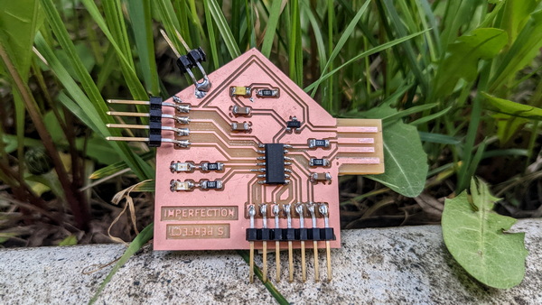
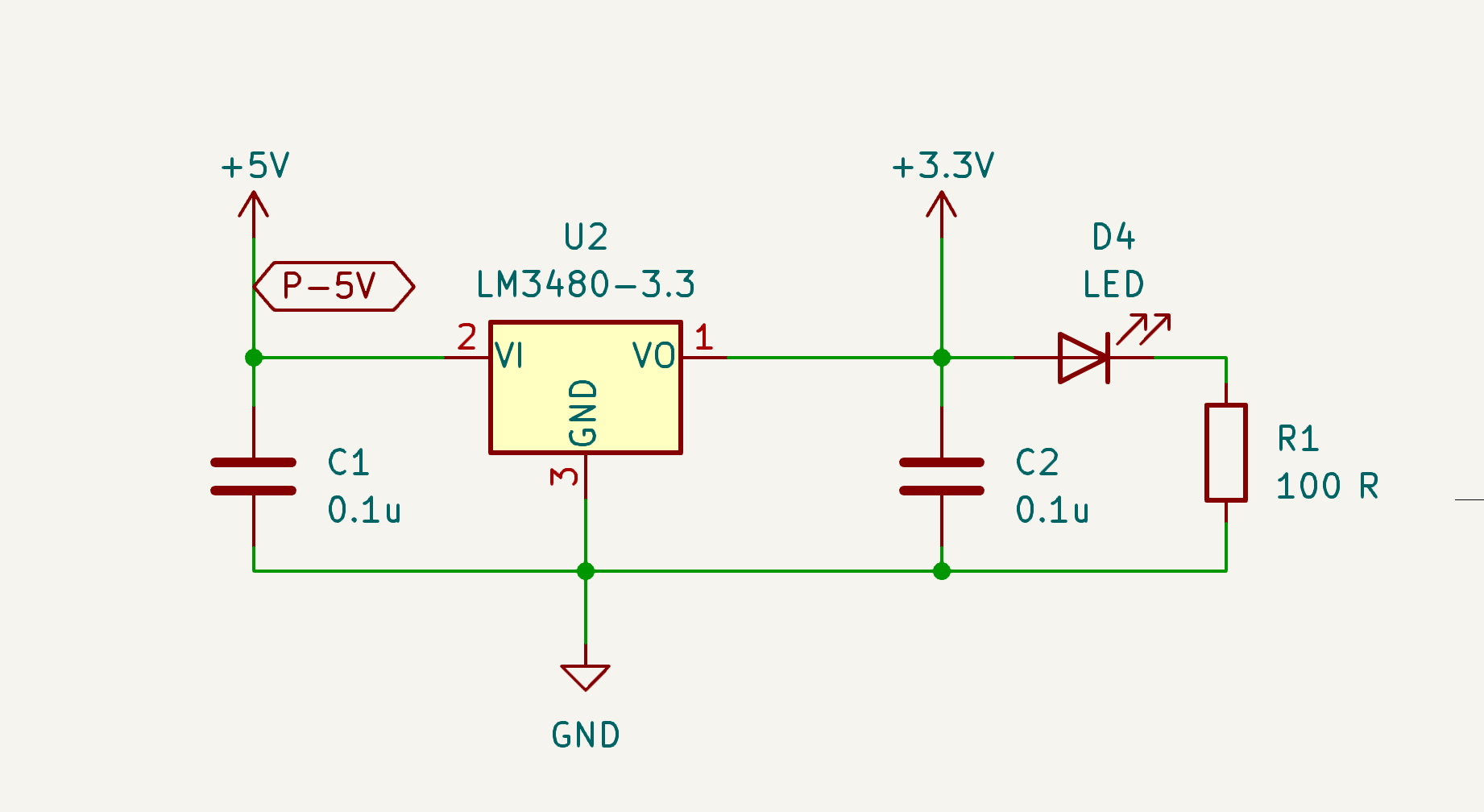
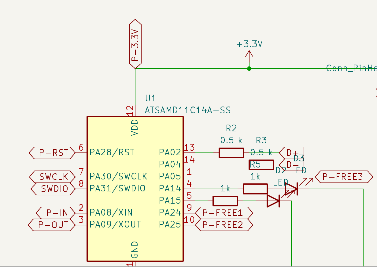
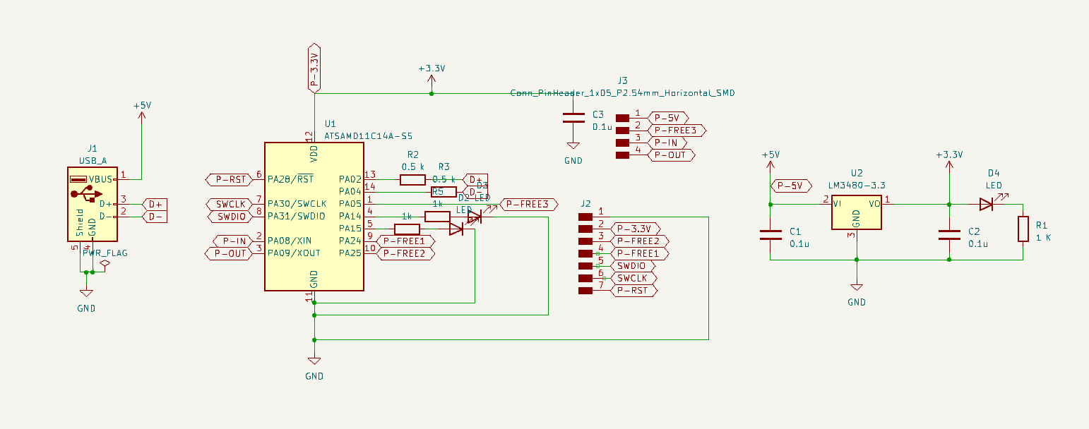
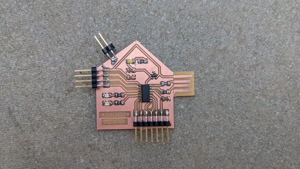
I took the Power supply and USB part from my old schematics. For this PCB I used the ATSAMD11C14-U microcontroller.
This time, I have added pins for both 5V and 3.3V power supply. This addition provides me with the flexibility to connect an input device, such as the moisture sensor, and an output device, like the water pump.
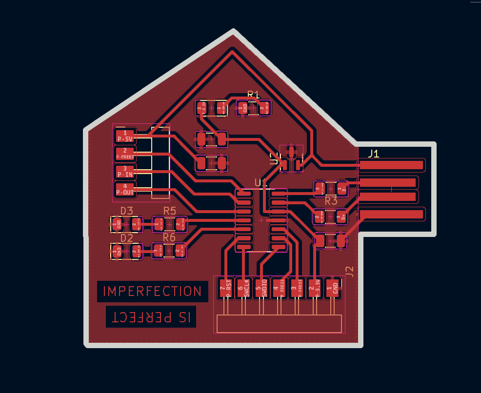
That’s what I got:
The next stage, which happens to be my favorite, involves assembling the perfect puzzle of components.
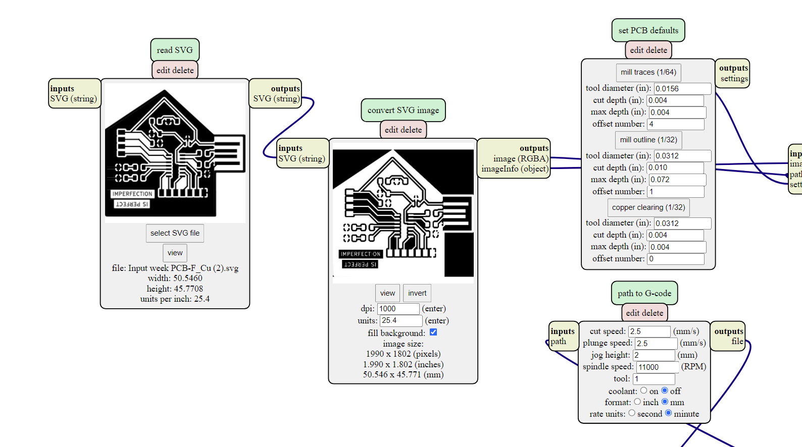
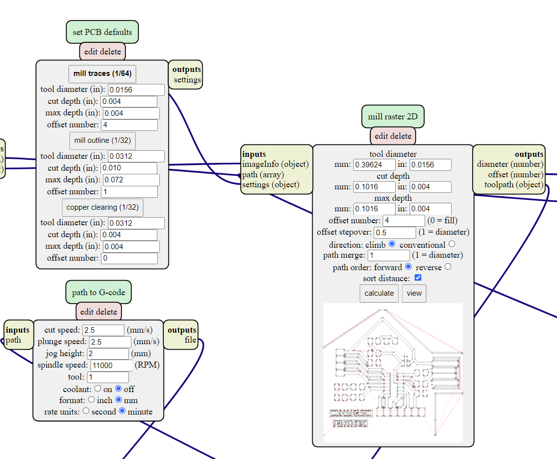
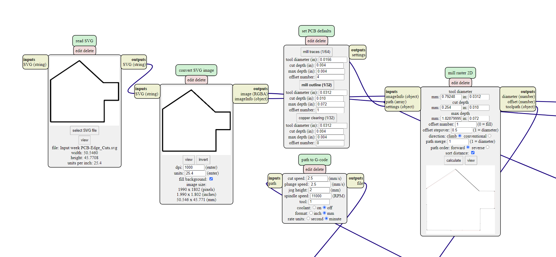
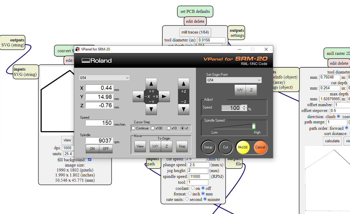
Now comes the milling process, an essential step in the electronics production. The detailed description of this process can be found in the documentation of Electronics Production week.
After soldering the components onto the PCB, I noticed that I had initially included only one ground pin. However, realizing the importance of proper grounding, I quickly rectified the issue by adding two additional ground pins.
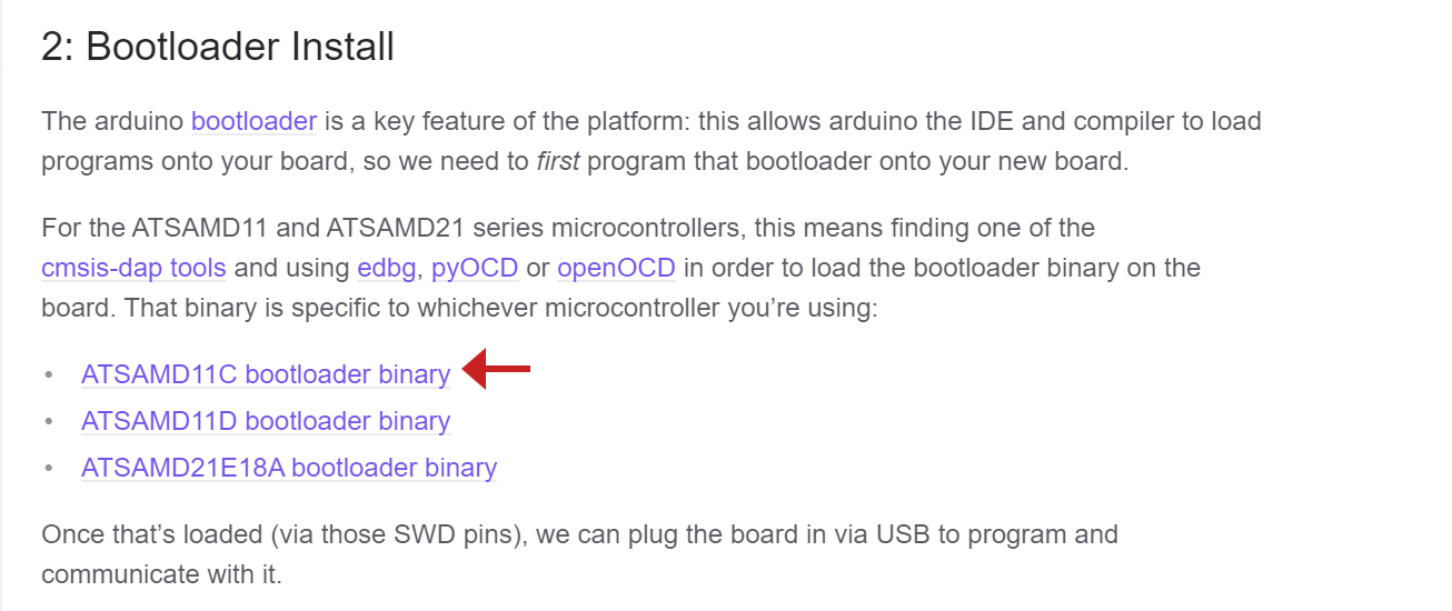
It’s now time for the bootloader installation, a crucial step in preparing the PCB for programming. Installing the bootloader allows us to easily upload and update the firmware on the board. To guide you through this process, I have provided a detailed description in my Output Devices week documentation. You can find the step-by-step instructions and necessary resources here.
During this phase, I encountered the need to download a specific bootloader that matches the microcontroller used in my project. Each microcontroller has its own compatible bootloader, which is necessary for seamless communication and programming.
During the installation of the bootloader, I encountered an error that momentarily hindered the progress of the process. However, with some troubleshooting and experimentation, I was able to identify the root cause of the issue. It turned out to be related to certain components and soldering connections.
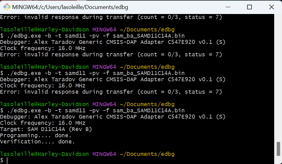
This experience taught me the importance of meticulous soldering and component placement, as even minor inconsistencies can have an impact on the functionality of the system. Through perseverance and hands-on problem-solving, I was able to overcome the obstacle and continue with the next steps of the project.
Moisture Sensor
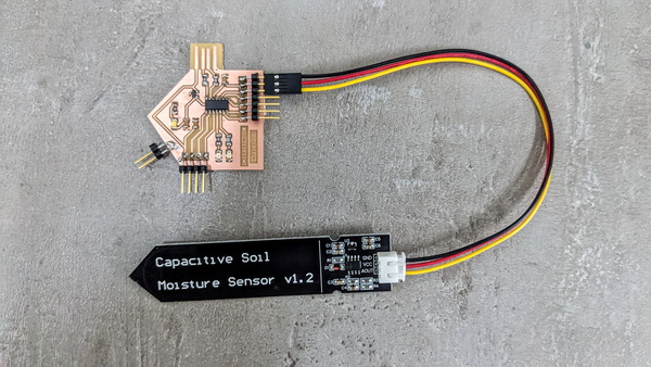
The Capacitive Soil Moisture Sensor V2.0 that I used, is an electronic device designed to measure the moisture content in soil. It is a popular sensor used in various applications, including gardening, agriculture, and environmental monitoring. This sensor operates on the principle of capacitance, where changes in soil moisture levels affect the electrical capacitance between the sensor electrodes.
The sensor utilizes capacitive sensing technology to measure the moisture content in the soil. It works by measuring the dielectric constant of the soil, which is directly related to its moisture content.
The sensor electrodes are made from corrosion-resistant materials such as gold or stainless steel. This ensures durability and longevity, even when exposed to harsh soil environments.
It provides an analog output signal that is proportional to the moisture level in the soil. This analog signal can be easily interfaced with microcontrollers or other measurement devices for further processing and analysis.
The Capacitive Soil Moisture Sensor V2.0 can measure a wide range of soil moisture levels, from dry to wet conditions. This allows for versatile use in different soil types and moisture conditions.
Here you can discover more about this interesting sensor.
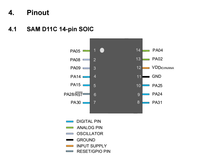
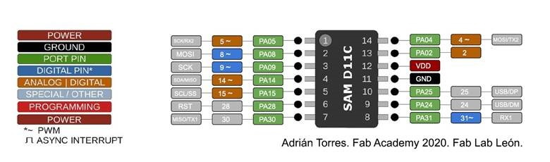
To program the PCB and establish the necessary connections, I utilized the Arduino software as my programming environment. To ensure proper pin assignments and compatibility, I referred to the pin map specific to the SAMD11C microcontroller. This pin map provided me with the necessary information on the available pins and their corresponding functionalities.
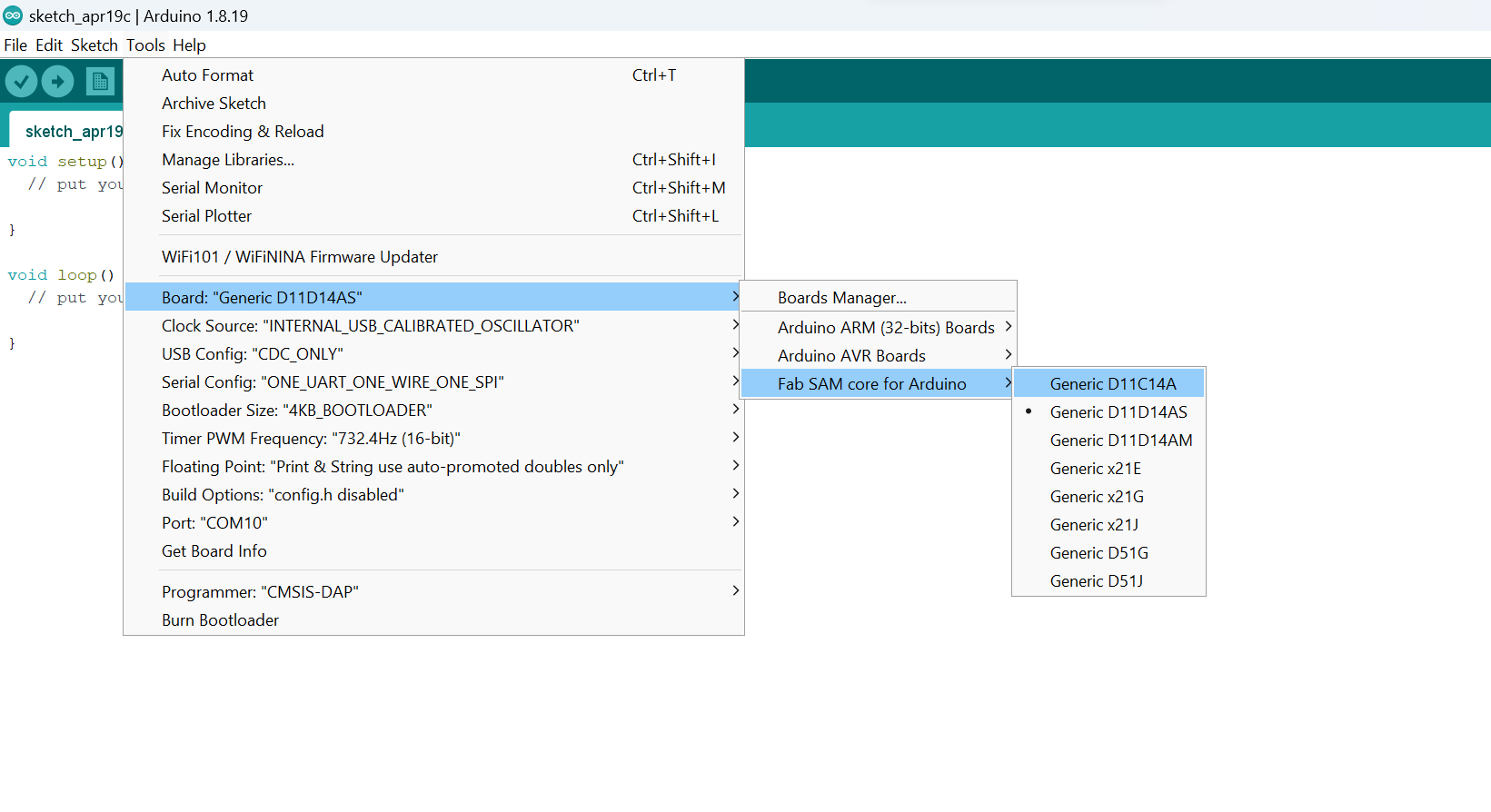
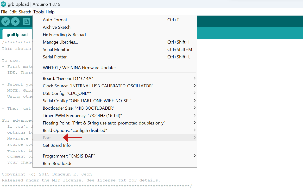
To configure the Arduino software for my specific microcontroller, I needed to set up the “Tools” section with the appropriate settings.
I took the logic of the code from this video, and in order to achieve the desired functionality, I made changes to the code by selecting the appropriate pins and mapping the analog values from 0 to 100.
// Define analog input pin for moisture sensor
#define MOISTURE_PIN 8

void setup() {
  pinMode(8, OUTPUT);
  Serial.begin(9600); // Start serial communication
}

void loop() {
  // Read analog input from moisture sensor
  int moisture = analogRead(MOISTURE_PIN);

  // Convert analog value to moisture percentage (0-100%)
  int moisturePercent = map(moisture, 239, 595, 0, 100);

  // Print moisture percentage to serial monitor
  Serial.print("Moisture: ");
  Serial.print(moisturePercent);
  Serial.println("%");

  delay(1000); // Wait for 1 second before taking next reading
}
During the process of working with this PCB, I encountered a familiar issue similar to what I had experienced with a previous PCB. The problem was that the PCB appeared to be “transparent” and was not recognized by the Arduino software.
After thorough inspection, I resoldered any questionable connections and checked for any potential short circuits or bridging between pins or components. I also ensured that all the components were correctly placed and securely soldered to their respective pads.
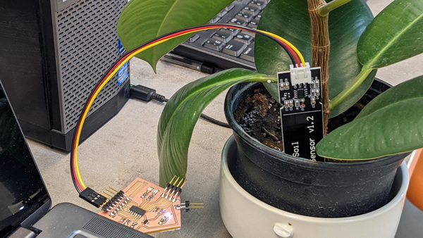
In my pursuit of finding an effective solution for testing the moisture sensor, I came across the board designed by Fab Academy student Maxime Richard. Recognizing the potential of his board to fulfill my requirements, I decided to utilize it for my testing purposes.
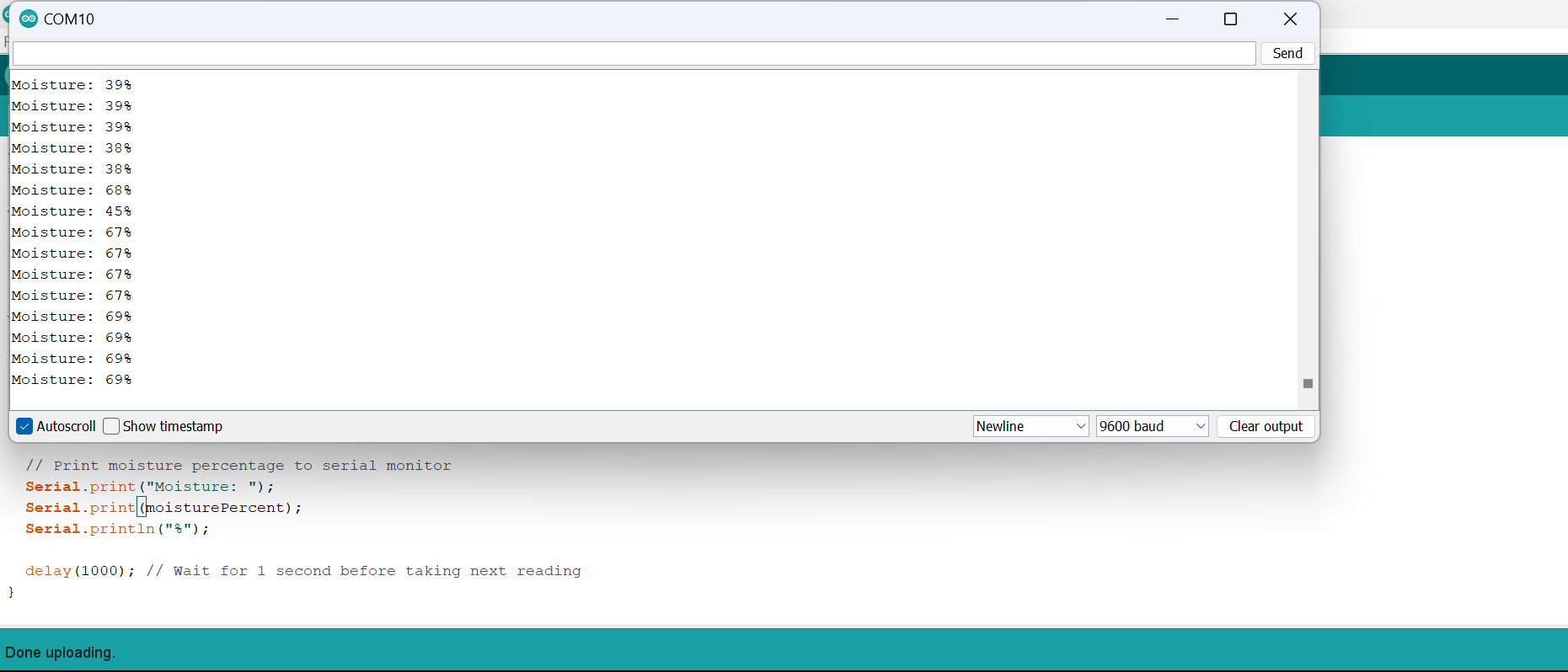
In the video demonstration, you can observe the real-time display of various values on the screen, which correspond to the changes in humidity levels detected by the moisture sensor.
To conduct a small experiment, I watered the plant and captured the process on video. As you closely observe the numbers displayed on the monitor, you’ll notice a noticeable change in response to the introduction of water to the plant’s soil.
This video demonstration serves as evidence of the functionality and responsiveness of the capacitive soil moisture sensor. It showcases its ability to detect and measure changes in moisture content accurately.
It was intriguing to observe instances where the moisture percentage displayed counterintuitive behavior, decreasing even when there was more humidity present, and vice versa. This unpredictability prompted me to investigate the underlying factors and refine my understanding of the sensor’s behavior.
To address this issue, I plan to further explore and refine the calibration process for the moisture sensor. By conducting additional tests and making adjustments to the sensor’s sensitivity and threshold values, I aim to achieve more accurate and reliable readings that align with the actual moisture levels in the soil.
Other Experiments with Sensors
During my time at the Fab Academy, I had the opportunity to explore and work with various sensors, each offering unique capabilities.
-
One such experience was with a rain sensor in Networking and Communication week using an Arduino board and connecting it to the Servo motor.
-
One of the exciting experiments I conducted during my Fab Academy journey involved working with a sound sensor and integrating it into my PCB project. The goal was to create a responsive system that could detect sound and trigger certain actions based on the sound input. You can discover more in my Final Project documentation.
Conclusion
Throughout this week, I focused on exploring the capabilities of a capacitive soil moisture sensor and integrating it into my PCB project. My aim was to create a responsive system that could accurately measure soil moisture levels and provide corresponding outputs.
One of the key highlights of this week’s work was successfully incorporating the capacitive soil moisture sensor into my PCB design. By carefully connecting the necessary pins and ensuring proper electrical connections, I established a reliable interface between the sensor and the microcontroller.
By documenting my journey, methodologies, and results in my assignment page, I aim to share my experiences and contribute to the collective knowledge within the Fab Academy community. I believe that the insights gained from this project can inspire and guide others who are interested in working with capacitive soil moisture sensors or similar environmental sensing technologies.