Mechanical Design. Machine Design.
Task: Mechanical Design, Machine Design
Mechanical Design (part 1 of 2)
Group assignment:
- Design a machine that includes mechanism + actuation + automation + application
- Build the mechanical parts and operate it manually.
- Document the group project
Individual assignment:
- Document your individual contribution.
Machine Design (part 2 of 2)
Group assignment:
- Actuate and automate your machine.
- Document the group project
Individual assignment:
- Document your individual contribution.
Group assignment: Making a new CNC (ՄԵՍՐՈՊ)
Creative destruction or how it all began.
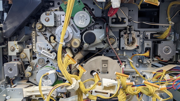
Machines literally build other machines; sometimes they are also crafted by other machines. The intricate cycle of materials, parts, and components that flow from one machine to another is an incredible feat of engineering. It’s a reminder that our views on disposability must shift. Everything we inherit from the past, be it knowledge, genes, or tools, is a precious gift that serves as the foundation for the present and the future. As I gazed upon the disassembled parts of an old printer, I was struck by a sense of wonder and awe, akin to that of visiting a museum or attending an inspirational exhibition. It dawned on me that building a machine is a true art form.
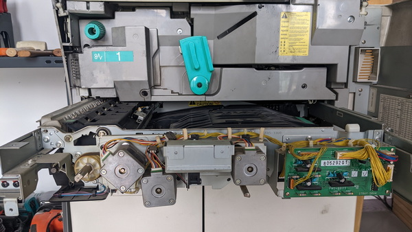
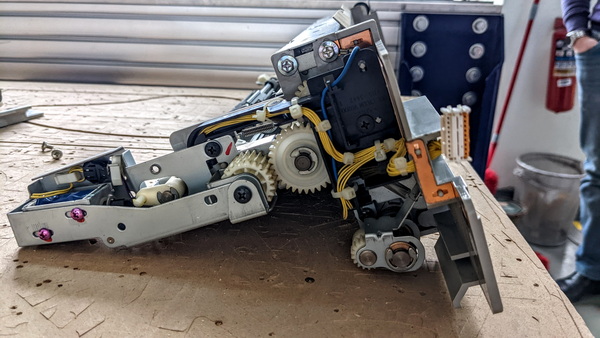
During the practical process of disassembling an old machine, we stumbled upon a trove of mechanical and electrical parts that we could have only dreamed of. Stepper motors, cooling fans, bearings, solenoids, and countless wires - this intricate web was truly magical. I’m confident that many of these seemingly insignificant parts, which may have been destined for the trash heap, will find new life and purpose in the innovative machines created at the Fab Lab.
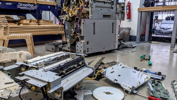
In recent years, there has been a growing movement towards sustainable technology and practices in order to combat the negative effects of industrialization on the environment. One promising approach is the use of old parts and components from outdated machines to build new, more eco-friendly machines. This method, sometimes referred to as “upcycling,” involves taking apart old machines and salvaging the still-functioning parts that can be repurposed in new machines. For example, an old computer may have a functioning hard drive or power supply that can be used in a new system, rather than being discarded as electronic waste.
Upcycling not only reduces electronic waste, but also saves energy and resources by minimizing the need to produce new components from scratch. Additionally, upcycling promotes a culture of repair and maintenance, encouraging people to value and extend the lifespan of their possessions. While upcycling may require more effort and expertise than simply buying new components, the benefits to the environment and economy make it a worthwhile pursuit. Furthermore, as technology advances and becomes more complex, upcycling can provide a valuable source of materials for future innovations.
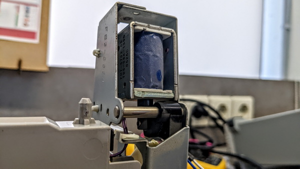
In the old printer, among the many “treasures” we found a solenoid, one of them was connected to the DC power supply. Look how beautiful it works!
Normally open (NO) and normally closed (NC)
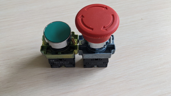
During the mechanical engineering process, we stumbled upon learning Normally Open and Normally Closed pushbutton switches:
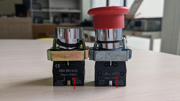
*Normally open (NO) and normally closed (NC) are two contact positions that are used to control the flow of current in electrical devices. When a switch is set to NO, it will allow current to flow through it when the circuit is completed. A NO position on a switch can also be referred to as an “on-off” position. Electricity needs to be applied for the switch to work; otherwise, it will remain dormant and not make contact.
On the other hand, NC switches have no need for electricity in order for them to work. They only need an uninterrupted connection to complete the circuit and operate.

Normally Open switches are used in a variety of different consumer electronics, including:
-
Light switch
-
Start button
-
Reset button
-
Normally open contact blocks
-
Footswitches
Normally closed switches also have a wide range of applications. They include:
-
Stop switches
-
Normally closed relays
-
Emergency stop buttons
-
Normally closed contact blocks
You can discover more about this topic in this article.
Limit switches: mechanical and optical
Limit switch is used to limit the position or stroke of the mechanical movement, so that the machine automatically stops, reverses, changes speed or automatically moves back and forth according to a certain position or stroke. It can be installed on relatively stationary objects (such as fixed mount or door frames) or moving objects (such as travelling crane, door, etc.). When the object is close to the stationary object, the lever of the limit switch drives the switch contacts open or close. According to the change of the contacts open/close state, the system can control the action of the circuit and machine.
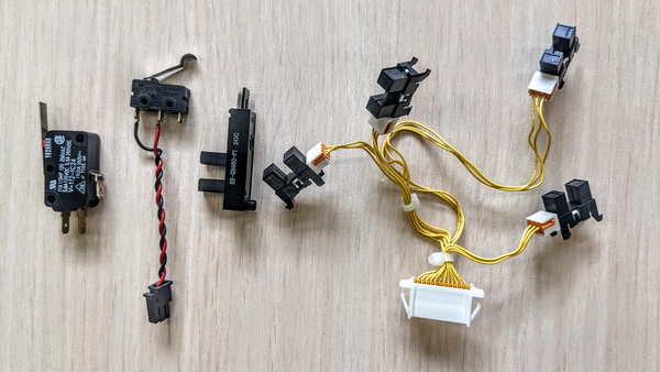
Mechanical and optical switches are two different types of keyboard switches that serve the same purpose - registering key presses.
Mechanical switches work by creating a connection between a metal piece located under the keycap and one on the keyboard. Once pressed, the circuit is closed, and the signal is sent to the computer that the key has been pressed. There are three main types of mechanical switches: linear, tactile, and clicky. Linear switches are quieter, require less force to press, and do not provide any tactile feedback. Tactile switches are louder, produce a bump in the middle of the keystroke, and offer a tactile response to the user. Clicky switches give a more pronounced bump and a loud “click” sound in the middle of the keystroke, which some users find satisfying.
On the other hand, optical switches use a process called light induction to detect key presses. When a key is pressed, the stem blocks an infrared light beam. An infrared sensor detects the absence of light and signals to the computer that the key has been pressed.
More about mechanical and optical switches - here.
Bearings
The other discovery for me was the types of Bearings:
-
Radial Bearings: Radial bearings are primarily designed to support radial loads, which are forces applied perpendicular to the axis of rotation. They utilize rolling elements such as balls or rollers to distribute the load and reduce friction. Radial ball bearings, for example, have multiple balls arranged in a circular raceway, allowing them to support radial loads while enabling smooth rotation. These bearings are commonly used in applications like electric motors, pumps, and conveyor systems.
-
Thrust Bearings: Thrust bearings are specifically designed to support axial loads, which are forces applied parallel to the axis of rotation. They are often used in applications where there is a need to prevent axial movement or provide support for components subjected to thrust loads. Thrust ball bearings use balls as rolling elements and are suitable for moderate axial loads. On the other hand, thrust roller bearings use cylindrical or tapered rollers to handle higher axial loads. Thrust bearings are commonly found in automotive transmissions, machine tool spindles, and helicopter rotors.
-
Friction Bearings: Friction bearings, also known as plain bearings or journal bearings, do not use rolling elements like balls or rollers. Instead, they rely on a lubricant, such as oil or grease, to reduce friction between the rotating shaft and a stationary surface. Friction bearings are typically composed of a shaft rotating within a sleeve or bushing. These bearings are simpler in construction and often used in low-speed or high-load applications where the lubricant can provide adequate support. Examples include certain types of motors, agricultural equipment, and some industrial machinery.
-
Tapered Roller Bearings: Tapered roller bearings are designed to support both radial and axial loads. They have cone-shaped rolling elements (tapered rollers) and inner and outer races with matching tapered surfaces. This design allows the bearing to handle forces applied perpendicular to the axis of rotation, as well as forces applied in one direction parallel to the axis. Tapered roller bearings are commonly used in automotive wheel bearings, gearboxes, and heavy machinery where combined radial and axial loads are present.
Each type of bearing has its own specific advantages and limitations, making them suitable for different applications based on load requirements, speed, and operating conditions. It is important to consider these factors when selecting the appropriate bearing type to ensure optimal performance and longevity.
Creality 30 Assembling
Now let me take you through our assembly and adjustment process for our new Creality 30 3D printer. It will help as after to print the parts for CNC machine.
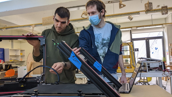
We started by unboxing the Creality 30 3D printer, carefully inspecting all components to ensure everything was present and undamaged. Following the provided user manual, we assembled the frame by securely attaching the frame components together using the provided screws and bolts. Next, we mounted the print bed onto the designated points on the frame and made sure it was level and properly positioned. We then installed the filament holder, attaching it securely to the frame.
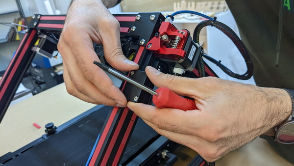
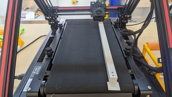
Since the Creality 30 is a belt printer capable of printing infinitely long parts, we paid close attention to adjusting the belt tension. Following the instructions provided in the user manual, we adjusted the tension of the belt using the belt tensioning mechanism. We aimed for a balance where the belt was taut enough to prevent slipping but not overly tightened, allowing for smooth and accurate printing.
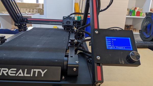
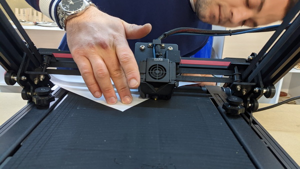
To guarantee precise and consistent prints, we checked and adjusted the alignment of the printer’s axes. We used the printer’s control panel or interface to level the print bed in the Y-axis direction, ensuring it was parallel to the belt’s movement. Additionally, we verified the smooth movement of the X-axis gantry and made any necessary adjustments to ensure it moved along its intended path without any issues.
With the assembly and adjustments completed, we installed the necessary slicing software and configured it with the appropriate settings for our Creality 30 printer. We initiated test prints to validate the printer’s performance and made any minor adjustments as needed to optimize print quality and accuracy.
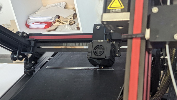
Upon our successful assembly and adjustments, we were able to print an impressive moving axis for our CNC machine, exceeding a length of 500mm.
3D Printing
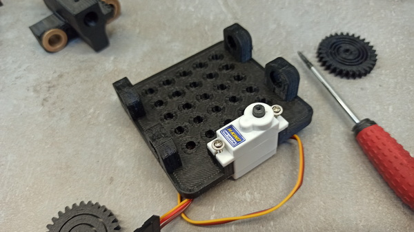
In our CNC machine assembly, we specifically opted for the printable parts designed by Quentin Bolsée to form the frame. We consciously decided not to make any modifications to these parts, as they were purposefully crafted to meet our requirements for structural integrity and stability.
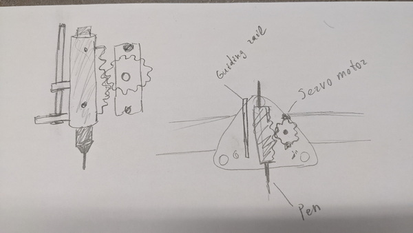
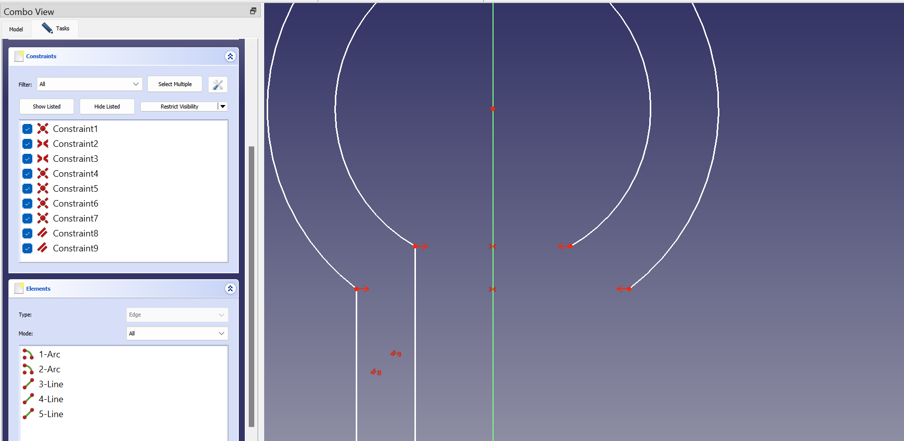
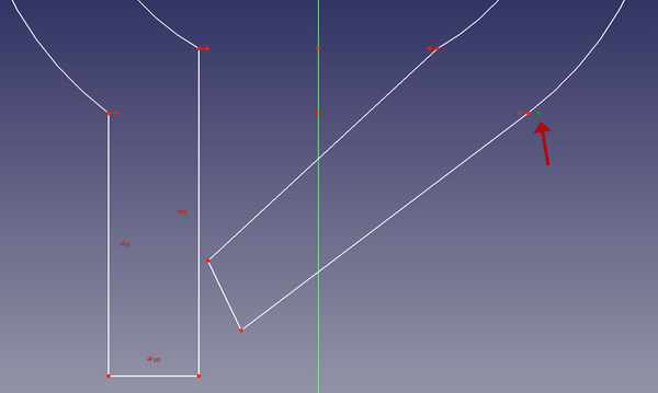
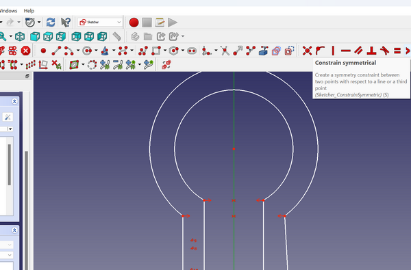
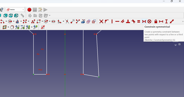
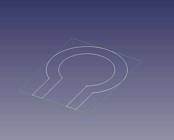
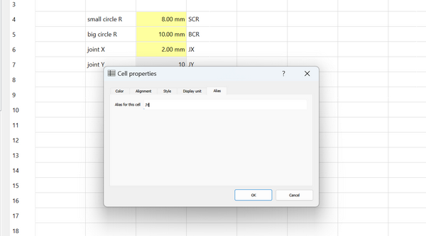
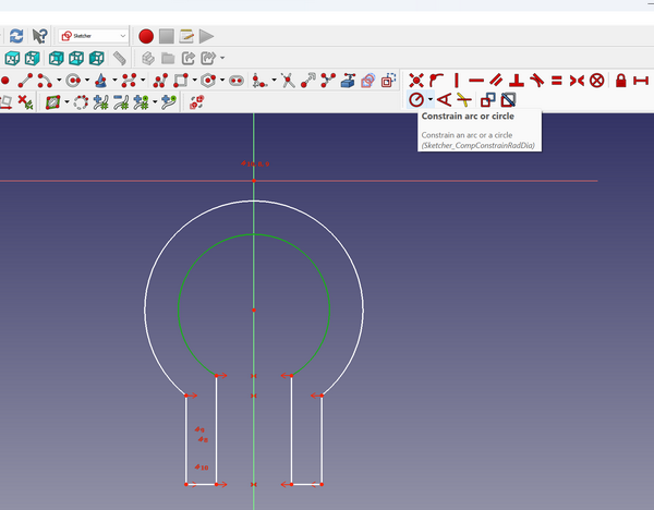
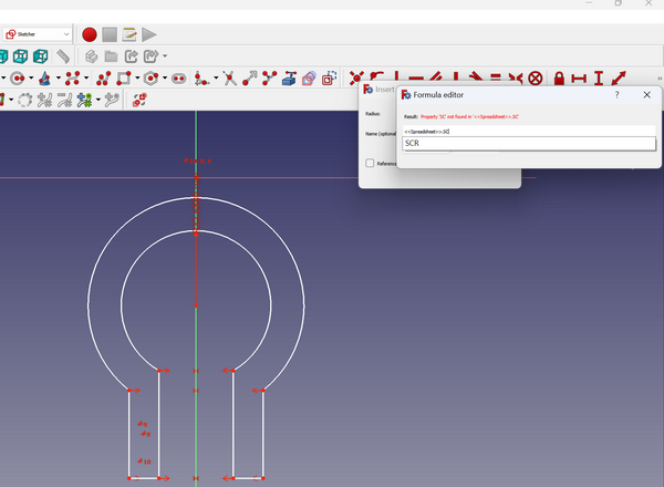
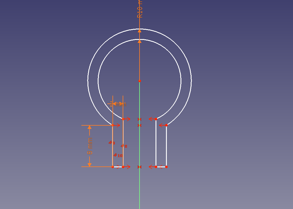
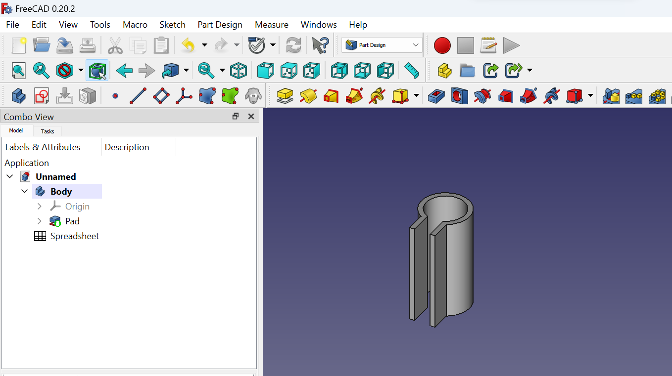
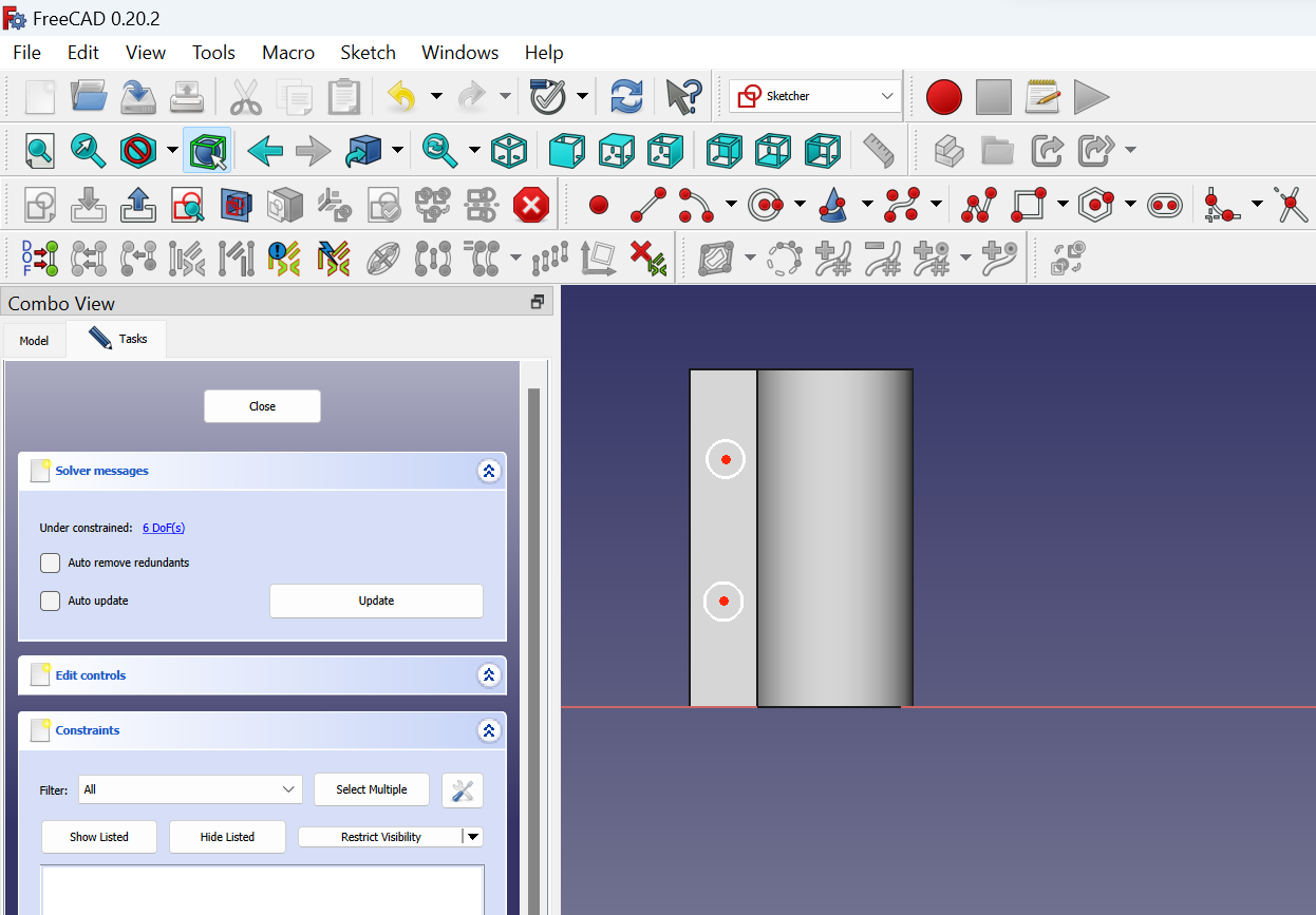
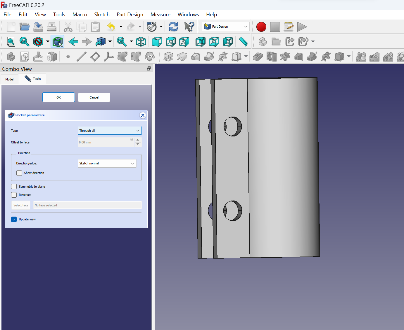
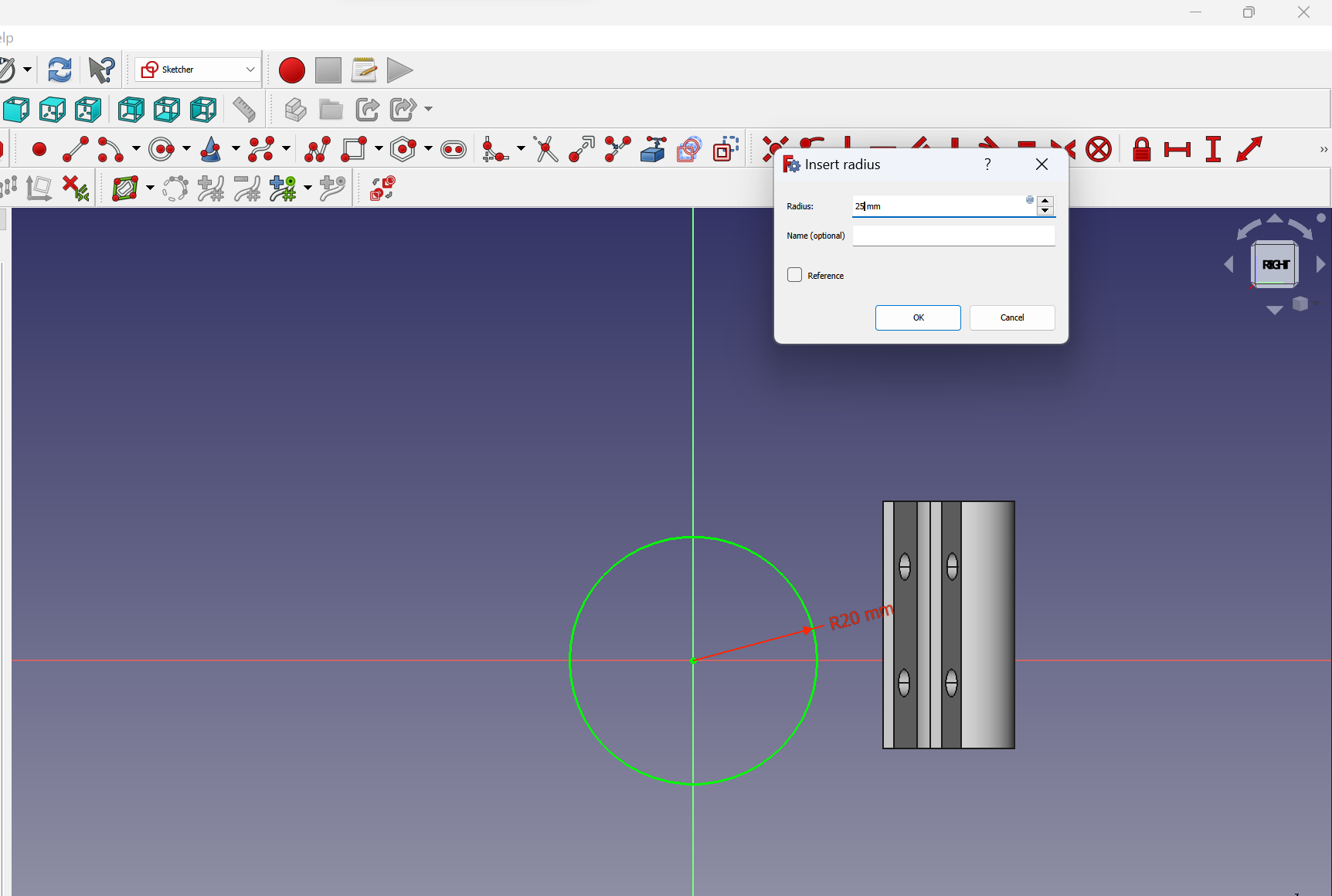
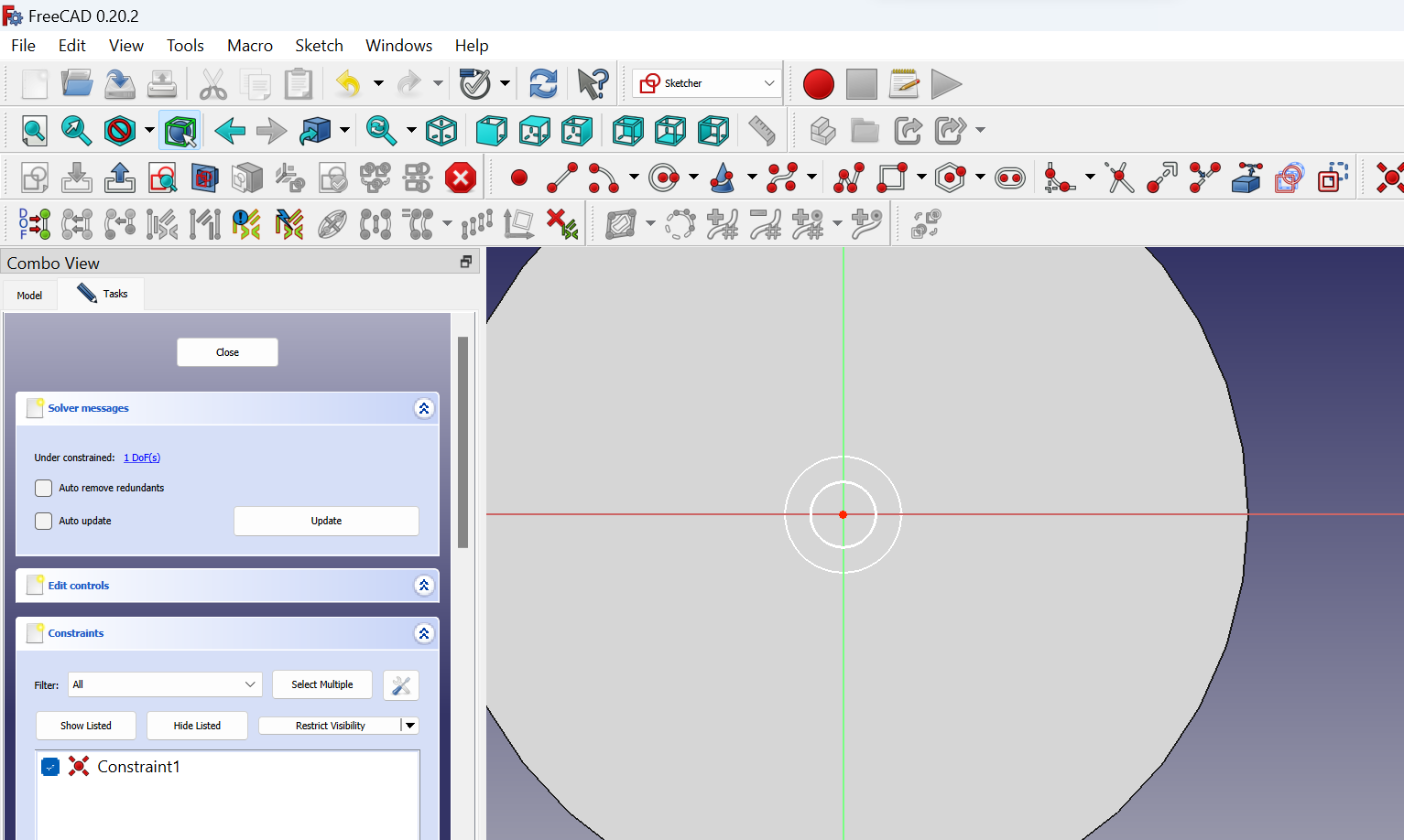
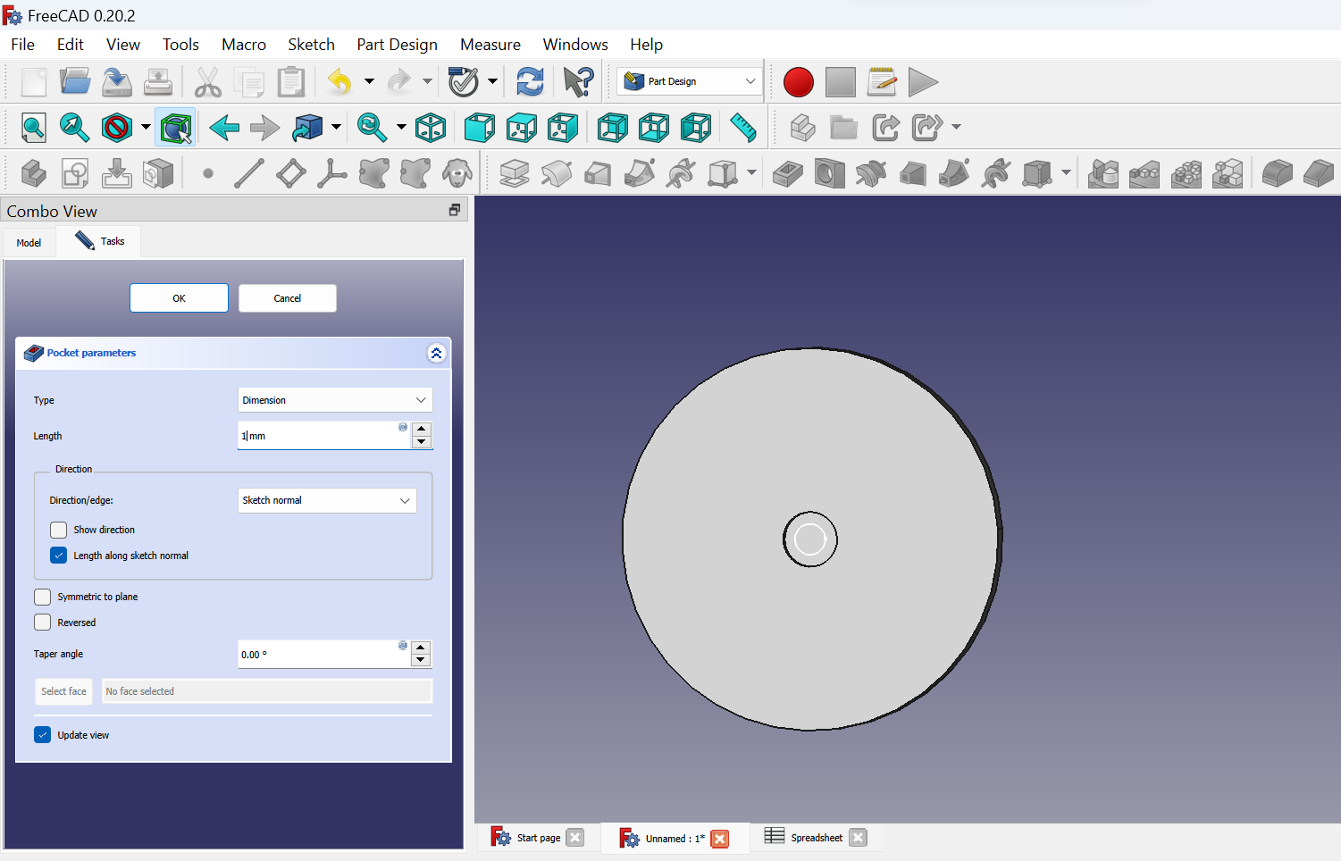
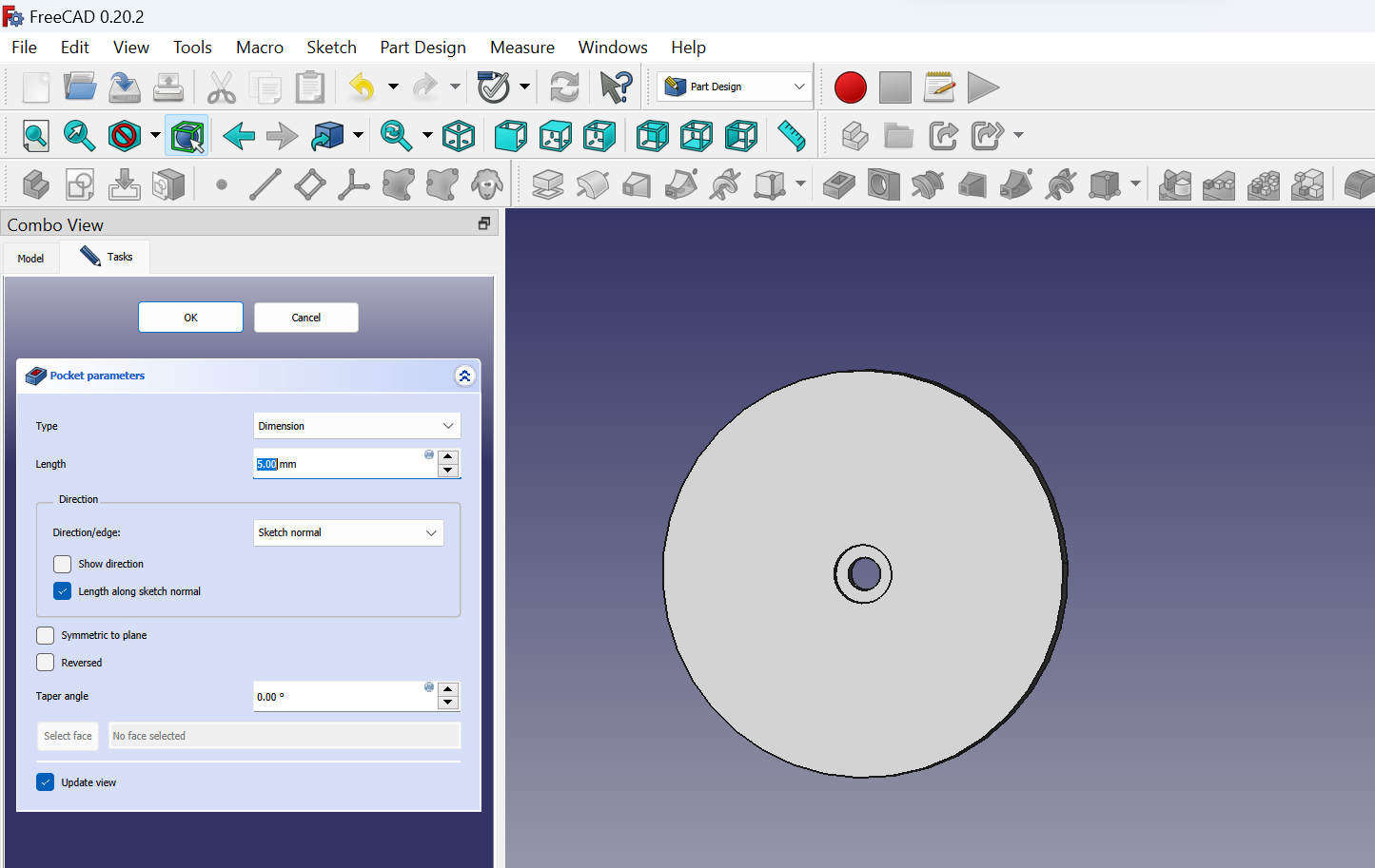
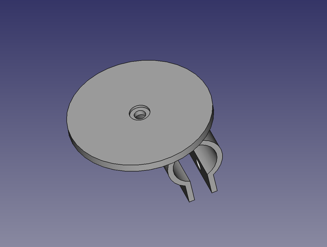
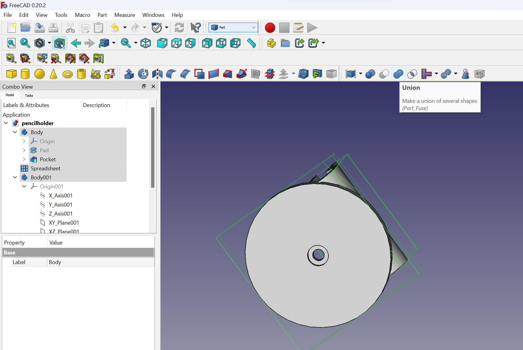
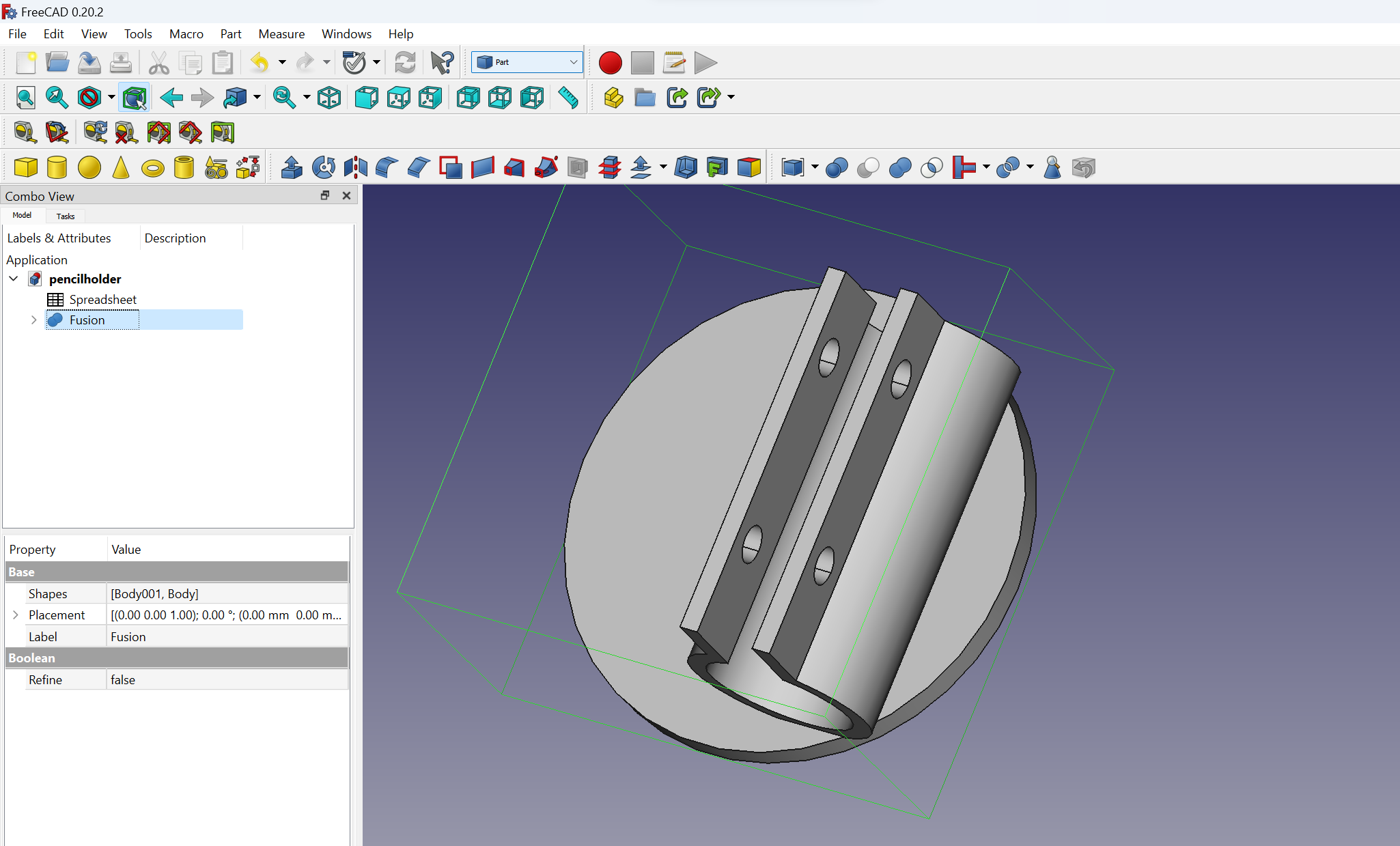
The development of the pencil holder mechanism required considerable time and thought. We went through multiple iterations and design changes before arriving at the optimal solution. As part of our efforts, I personally designed one of the pencil holders in FreeCAD. Allow me to take you through the step-by-step process of creating the mechanism:
CNC Assembly
To ensure stability and support for our CNC machine, we constructed a robust frame using a combination of 3D printed parts and metallic axis. We meticulously assembled the frame components, adhering to the predetermined design and establishing secure connections to maintain rigidity across the entire machine. This approach allowed us to leverage the strength and durability of the metallic axis while incorporating the versatility and customization possibilities offered by 3D printed parts. By combining these elements, we achieved a sturdy frame that provided the necessary stability for precise and reliable CNC operations.
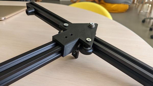

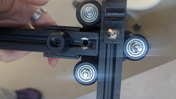
The XY core system forms the foundation of our CNC machine, enabling precise movement along the X and Y axes.
The XY core system, also known as the XY table or XY stage, is a fundamental component in the construction of a Computer Numerical Control (CNC) machine. The XY core system provides precise and controlled movement in the X and Y directions, allowing for accurate positioning of the cutting tool or workpiece during CNC machining operations.
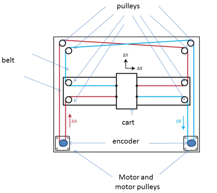
The XY core system typically consists of a table or stage that moves along the X and Y axes, driven by motors and controlled by the CNC system. The construction and design of the XY core system can vary depending on the specific CNC machine and its intended application.
It allows the CNC machine to move the tool horizontally (X-axis) and vertically (Y-axis) across the work area, facilitating operations such as cutting, drilling, milling, engraving, or any other machining process.
More about Core XY here!
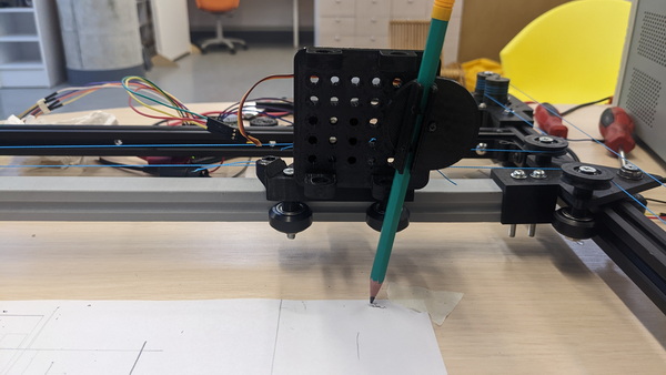
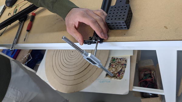
Here, we invite you to delve into the fascinating process of manually operating the XY core system. This remarkable system allows for precise manipulation and control, opening up a world of possibilities.
The automation
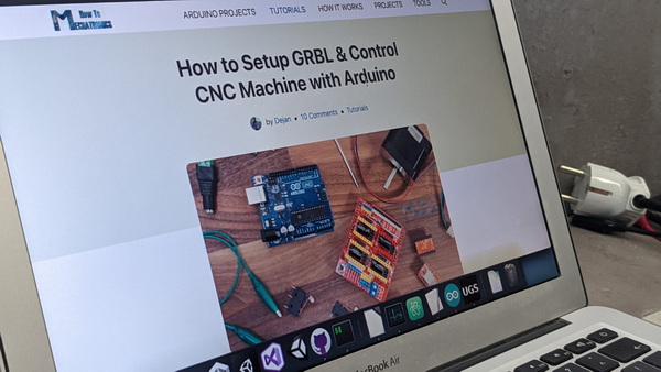
Now let describe the process of how we achieved this automation using a CNC shield and GRBL:
We meticulously followed a comprehensive tutorial, meticulously going through each step, to guide us in our automation endeavor. This tutorial served as our invaluable resource, providing clear instructions and guidance on integrating the CNC shield and GRBL firmware into our CNC machine.
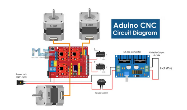
To automate our CNC machine, we integrated a CNC shield into the system. The CNC shield serves as an interface between the stepper motors and the control board, allowing for precise control and coordination of movements.
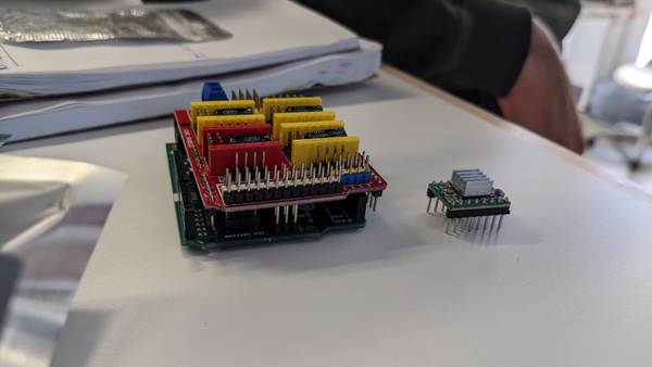
Connection and Wiring: We carefully connected the stepper motors to the CNC shield, ensuring proper wiring and alignment. The CNC shield typically provides dedicated ports for each motor, making it easier to establish the connections. We followed the manufacturer’s instructions and documentation to ensure correct wiring and secure connections.
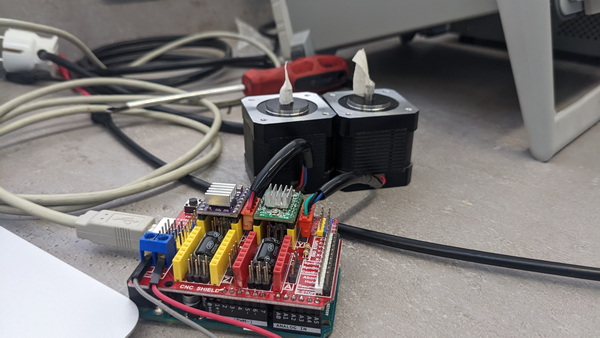
Installation of GRBL: Next, we installed GRBL, onto the control board. GRBL serves as the brains of the CNC machine, interpreting G-code instructions and translating them into precise motor movements.
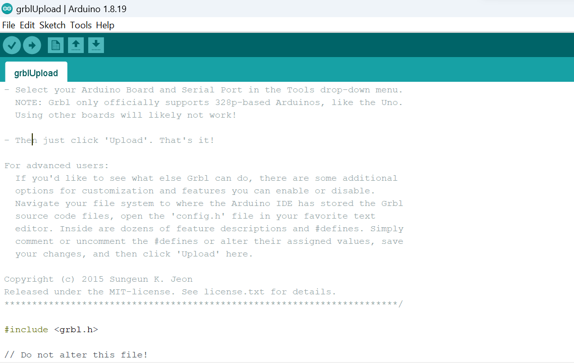
Configuration and Calibration: Once GRBL was installed, we proceeded to configure and calibrate the system. This involved adjusting various parameters in the GRBL settings to match the specifications of our CNC machine.
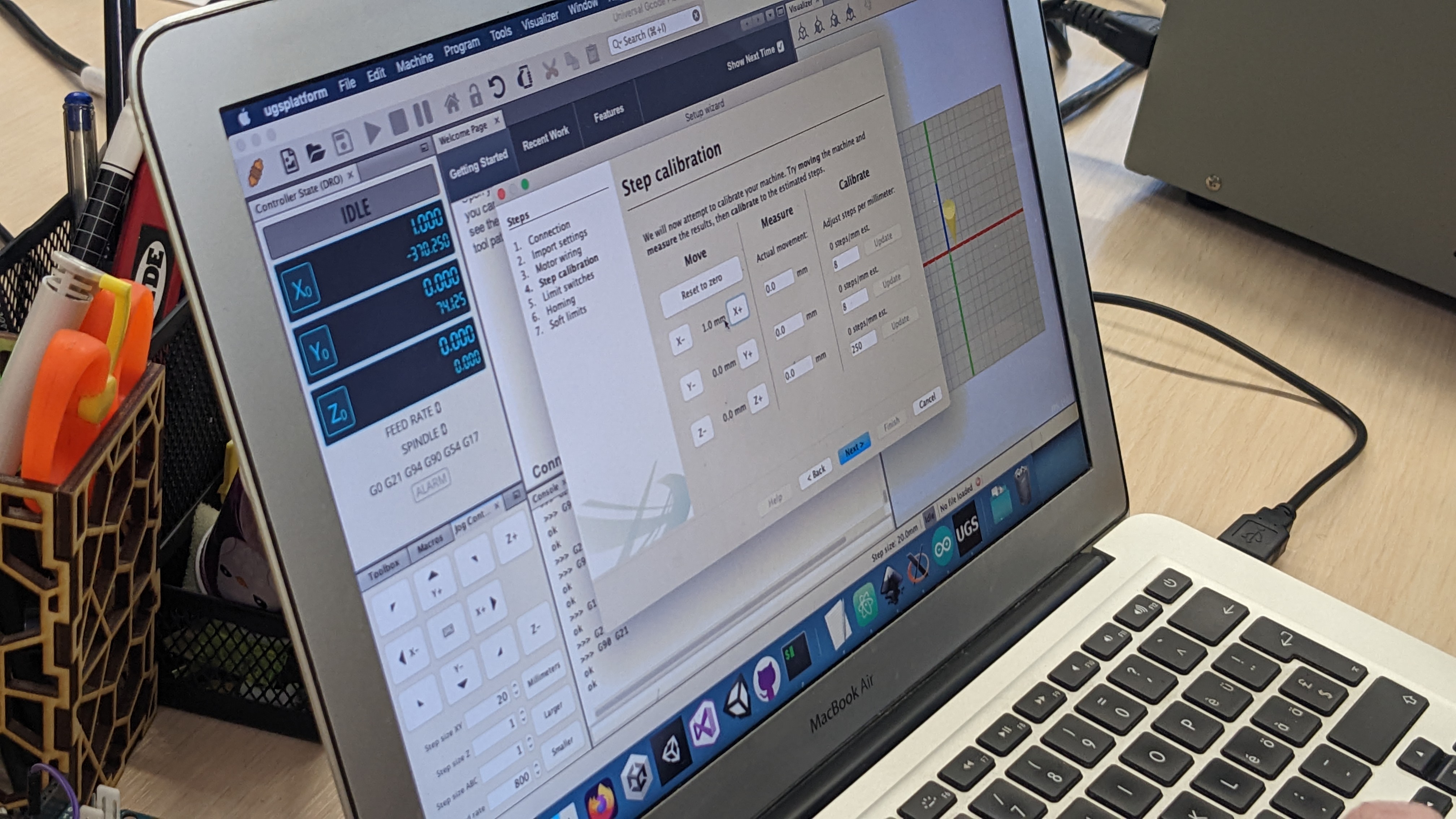
Control Software Setup: With the hardware and firmware in place, we set up control software to interface with the CNC machine. We used the popular software Universal G-code Sender (UGS) that supports GRBL. We configured the software to establish a connection with the CNC shield and control board, enabling us to send G-code instructions and commands to the machine.
Conclusion
Our work this week perfectly aligns with the inspiring concept of machines making machines in a Fab Lab. As we dedicated ourselves to building and automating our CNC machine, we embodied the essence of this transformative idea.
By assembling our CNC machine using a combination of 3D printed parts and metallic axes, we took a step towards self-replication. We utilized the power of digital fabrication to create the very tools that enable us to fabricate and innovate further. This self-sufficiency not only reduces costs but also empowers us to explore new possibilities and customize our machines to suit our specific needs.
With each step we’ve taken, we’ve embarked on a path of creativity, learning, and collaboration. As we continue our Fab Lab journey, we carry the spirit of machines making machines, fueling our passion for digital fabrication, and driving us towards new horizons of innovation and exploration.