Computer Controlled Cutting
Assignment
group assignment:
- characterize your lasercutter’s focus, power, speed, rate, kerf, joint clearance and types
individual assignment:
- cut something on the vinylcutter
- design, lasercut, and document a parametric construction kit, accounting for the lasercutter kerf, which can be assembled in multiple ways
Group assignment
The group assignment proved to be invaluable in enhancing my understanding of the laser cutter. Prior to joining Fab Academy, the only machine I had experience working with was the laser cutter in our Fab Lab EPILOG MINI LASER 40W. This old machine has its own unique character and often requires alternative parameter settings for cutting and engraving, distinct from those outlined in the manual.
Previously, I had relied on my intuition and past experience working with various materials to make the necessary adjustments.
Now we decided to try to engrave and cut 3 different materials: cardboard, playwood and acrylic:
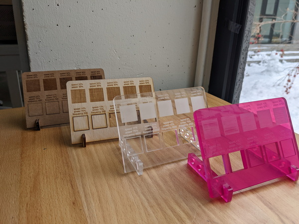
You can discover more about our group assignment here.
Research
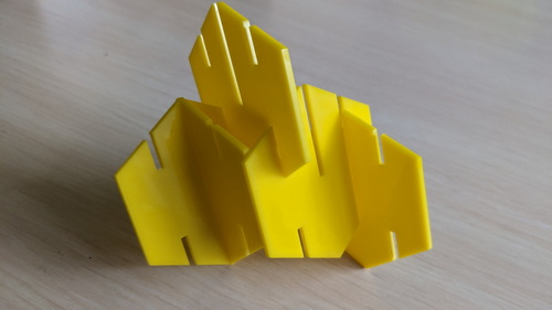
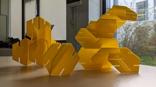
During my research, I came across fascinating examples of how simple joints can create intricate figures and even sculptures with just one or two details. I found some of these examples on Pinterest and thought they could inspire you as well. Take a look:

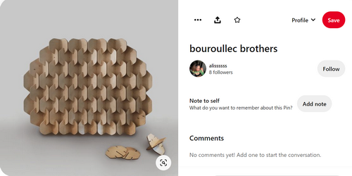
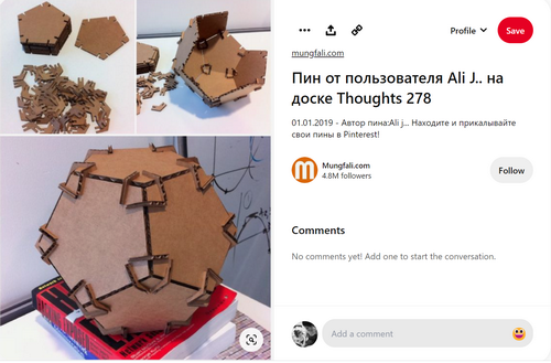
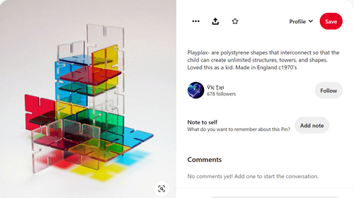
So, I decided to take inspiration from one of the examples and create my detail.
Creating a part
Oh FreeCAD - my suffering
Parametric design is an approach to creating 3D models that allows for the easy modification and customization of designs through the use of parameters or variables. In FreeCAD, a popular open-source 3D modeling software, parametric design is a powerful feature that can greatly improve productivity and efficiency.
To create a parametric design in FreeCAD, you start by defining the basic geometry of your model using sketches, solid modeling, or any other method. Then, you can add parameters to the model, which act as variables that control various dimensions and properties of the design.
For example, let’s say you want to create a simple box with a variable width, height, and depth. In FreeCAD, you can create a sketch of the box and use the “Pad” tool to extrude it into a 3D shape. Then, you can add parameters for the width, height, and depth, which can be adjusted later to modify the shape of the box.
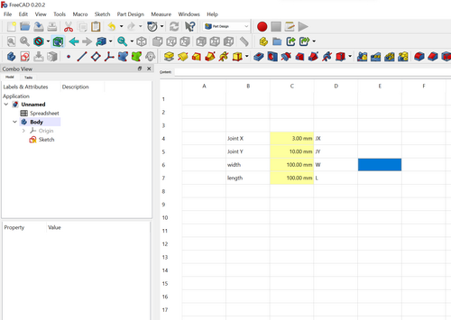
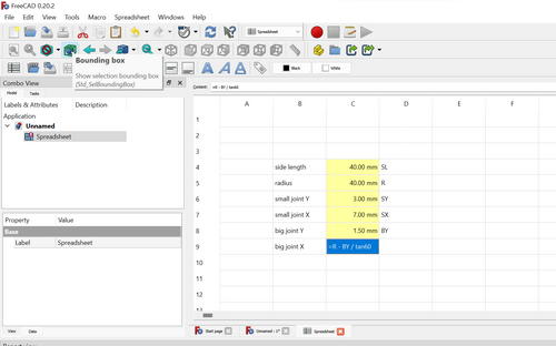
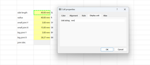
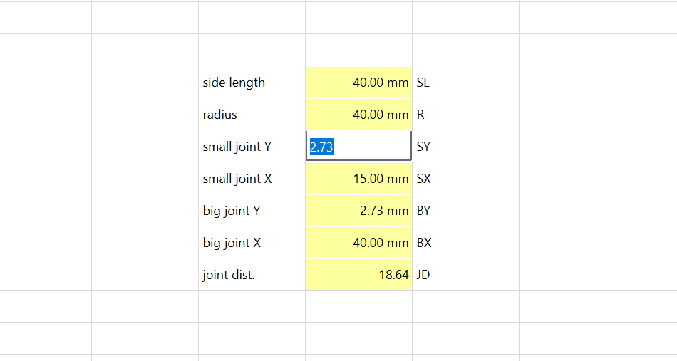
For the parametric design I started to creat a Spreadsheet. Here are the first parameters.
I was wrong to think that I can create my design in one sketch. You can see all my steps folowing next screenshots.
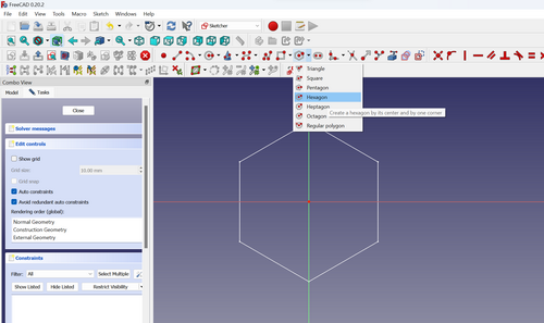
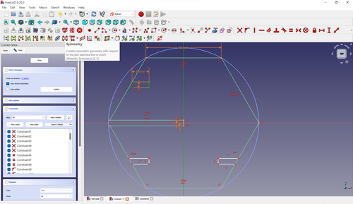
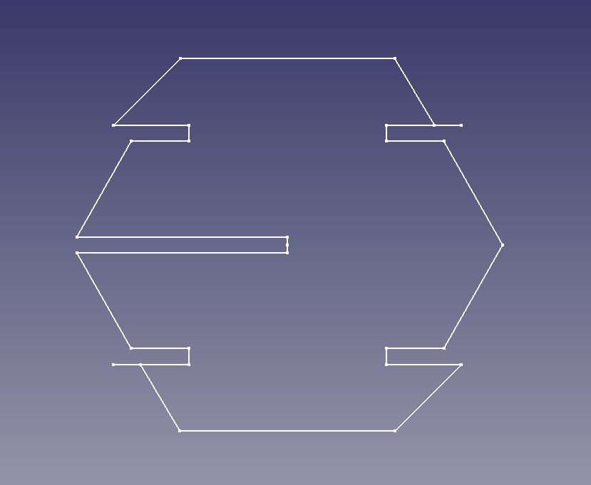
I chose Sketcher workbench. First I created a hexagone:
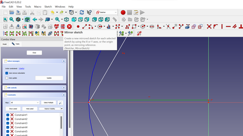
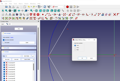
Now the big joint. I draw one part of my joint and used the tool Mirror sketch (mirror axis X) to get the second half. As you can see I am not professional finding simpe solutions. :) I want to notice that FreeCAD is a new tool for me that I explore during my work process.
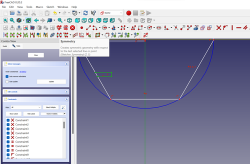
Now the small joints. I draw one joint and used the tool Symmetry to create other small joints.
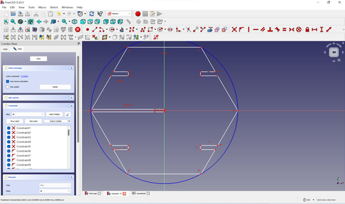
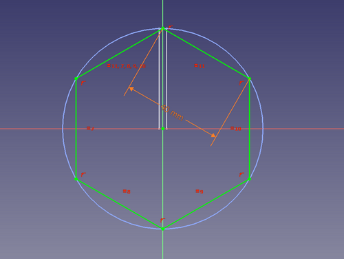
Now I need to determine the X value for my large joint. As you can observe, it is shorter than the hexagon’s radius.
As you may recall, the angles of a hexagon measure 120 degrees.
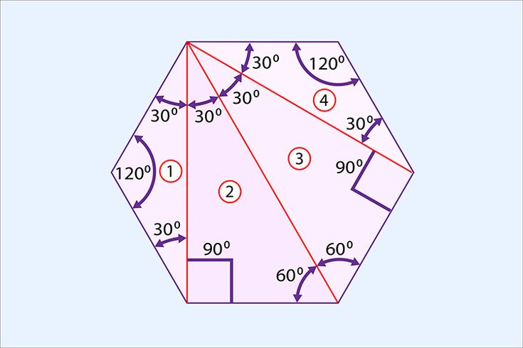
To address this, I employed the following formula:
R - BY/tan60
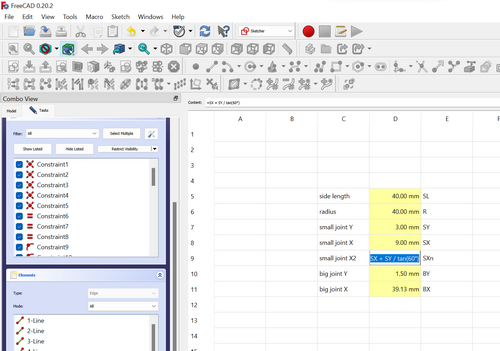
Now, let’s move on to the small joint. I have defined the shorter side of my joint as SX.
To calculate the length of the longer side, I have formulated an equation:
SX + SY/tan60
NOW THE “MAGIC”!!!
During the process, I encountered numerous unexpected errors. Additionally, when attempting to modify the parameters in the spreadsheet, I encountered a complex and problematic issue.
Later, when attempting to edit the sketch, I faced a peculiar visualization issue where only a dot appeared on the screen, preventing me from accessing the sketch.
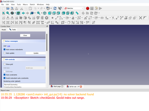
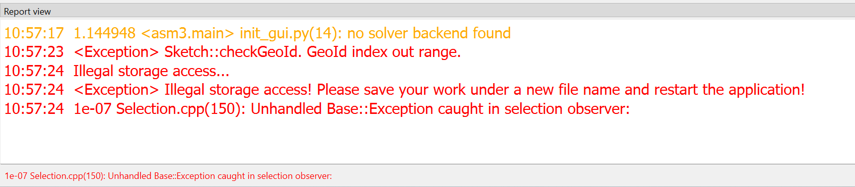
As I attempted to edit the sketch, the situation escalated further with an increased number of errors being displayed. Ultimately, FreeCAD abruptly shut down, impeding my progress in making the necessary modifications.
Since then, I have encountered the same issue every time I attempt to open the file, consistently experiencing the recurring problem and inability to access or work with the file successfully.
FreeCad - we become friends
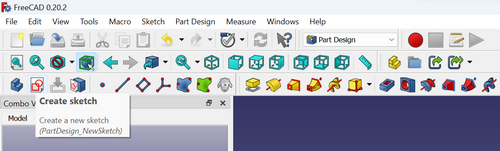
I decided to create a new drawing, adopting a different approach by using separate sketches for various joints and parts. This time, I worked within the Part Design workbench to accomplish my task.
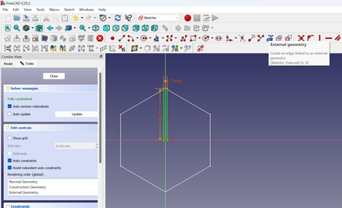
After successfully creating the hexagon, the subsequent step involved generating a new sketch for the joint. FreeCAD provides a helpful tool called External Geometry within the Sketcher workbench. By utilizing this tool, it became possible to incorporate another sketch as external geometry, thereby creating the new sketch for the joint.
The same with the small joints: new sketch and External geomerty.
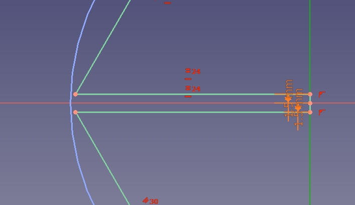
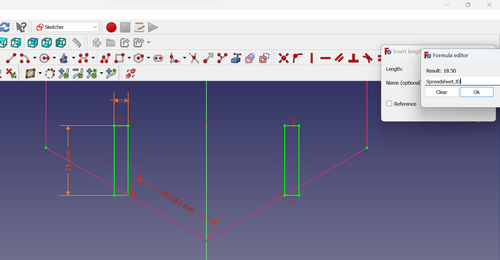
To assign values to the different sides of my sketches directly from the spreadsheet, I utilized the Constrain Distance tool. Instead of manually inputting the values, I clicked on the formula icon and selected the spreadsheet option. From there, I specified the name of the parameter whose value I desired to assign to the respective line. This method allowed for a dynamic and efficient way of updating and managing the values within the sketch using the spreadsheet data.
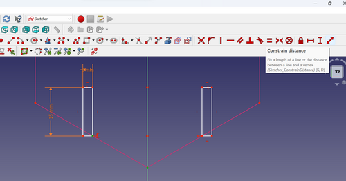
As you can notice, the line color is changing to green:
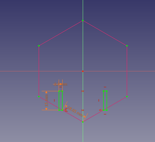
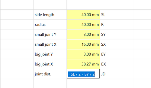
Additionally, I included a new parameter in the spreadsheet, which represents the distance of the small joint from the Y-axis. By introducing this parameter, I gained greater flexibility in adjusting and controlling the positioning of the small joint within the design.
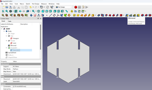
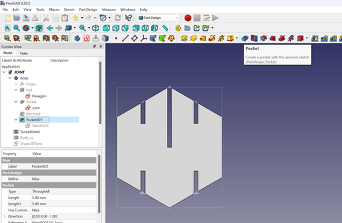
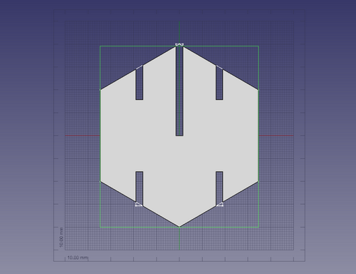
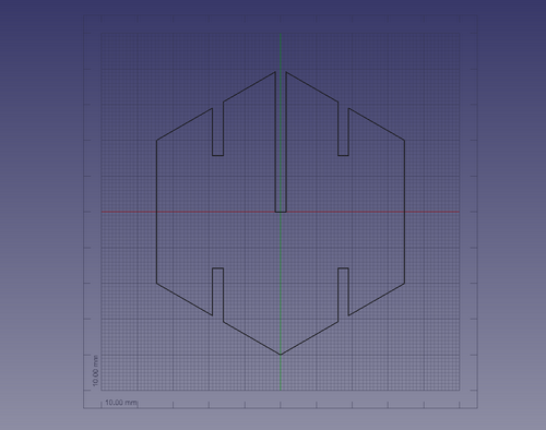
To create the additional two small joints, I employed the Mirrored tool, which allowed me to replicate the existing joint and position them symmetrically.
For the hexagon, I utilized the Pad tool to extrude and give it depth, while the Pocket tool was employed to cut out the joints, resulting in the desired shape and structure. These tools proved instrumental in shaping the components of the design according to the desired specifications.
Laser cutting
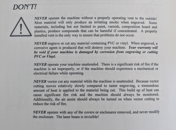
As you mentioned, the laser machine in your Fab Lab is the EPILOG MINI LASER 40W. While exploring the manual, you came across a crucial page that should always be readily accessible and visible for reference:
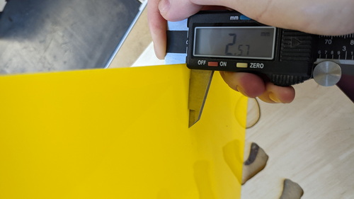
During my time at the Fab Lab, I discovered a preference for working with acrylic over plywood. Therefore, I decided to use a bright yellow acrylic material for my project. To ensure precision, I measured the thickness of the acrylic and found it to be 2.57 mm. This information is crucial for accurately designing and fabricating the components that will incorporate the chosen acrylic material.
Recognizing the significance of kerf thickness in laser cutting, I decided to conduct an experiment specifically focused on the acrylic material I selected. The goal was to measure the actual thickness of the kerf, which is the width of the material removed during the cutting process. This information would enable me to make necessary adjustments to the parameters in my parametric design before proceeding with cutting the actual model.
When working with a laser cutter, one of the most important aspects to consider is the setup of the focus of the kerf. The kerf refers to the width of the cut made by the laser, and the focus refers to the point at which the laser beam is concentrated to make the cut.
Setting up the focus of the kerf is crucial because it can affect the quality of the cut, as well as the speed and efficiency of the cutting process. If the focus is not properly set up, the laser beam may not be concentrated enough to make a clean cut, or it may be too concentrated, causing the material to burn or warp.
To set up the focus of the kerf, you need to adjust the distance between the laser lens and the material being cut. This distance can vary depending on the thickness and type of material, as well as the power of the laser.
In the display you can see the button focus.
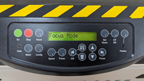
To adjust the laser focus for each batch of jobs, follow the steps below:
-
Activate the focus mode on the laser cutter. This will move the laser to its starting position.
-
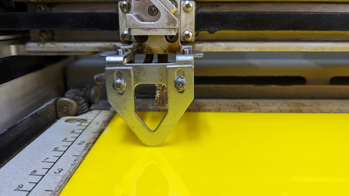
Position the spacer on the laser head. The spacer will be held in place by magnets. Use the up and down arrows to gradually lower or raise the head until the spacer is just lightly touching the material.
-
Once the desired focus is achieved, press the Reset button to finalize the adjustment.
By following these steps, you can accurately adjust the laser focus for each batch of jobs on the laser cutter.
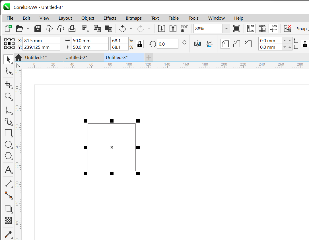
I drawed a square in CorelDraw 50x50mm.
I cut it in laser cutter. Now you can see the difference:
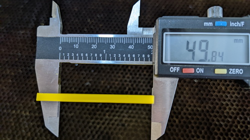
50 - 49,84 = 0.16
To ensure the accurate sizing of my drawing for laser cutting, I am now adjusting the parameters in the spreadsheet. Taking into account the measured kerf thickness, I have incorporated this value by adding it to the original material thickness. This adjustment allows for compensating for the material that will be removed during the cutting process, ensuring the final cut matches the desired dimensions of my design.
2,57 + 0,16 = 2,73
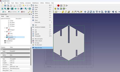
How to get 2D shape from 3D model? This video was very helpful to me.
In Draft workbench I chose Modification -> Shape 2D View:
Export as .svg:

Cutting the detail
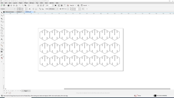
I open my file in CorelDraw and distribute over the entire surface:
Now, press CTRL+P to initiate the printing process. You have selected the laser cutter.
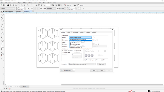
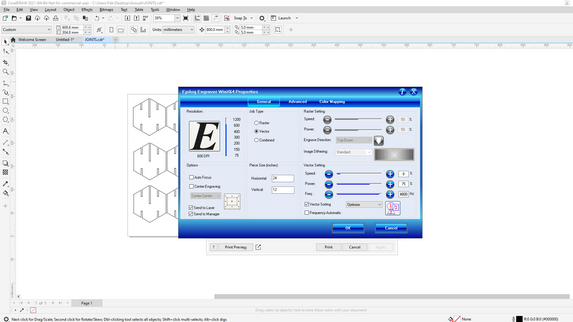
Now time to adjust the settings:
Here we have 3 options:
- Raster (for engraving)
- Vector (for cutting)
- Combined
I chose the option Vector and write the size of working surface: 24x12 inches.
To adjust the 3 parameters: Speed, Power and Frequancy, I explore the results of our group assignment and chose:
- Speed: 8
- Power: 75
- Freq: 4800

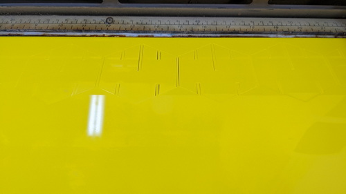
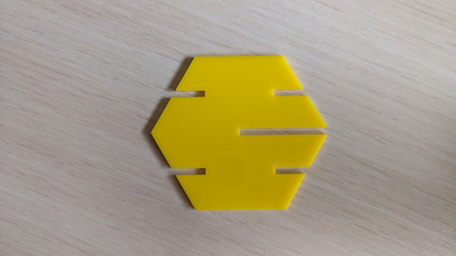
Behold the stunning outcome I have achieved:
Vinyl cutting
Drawing
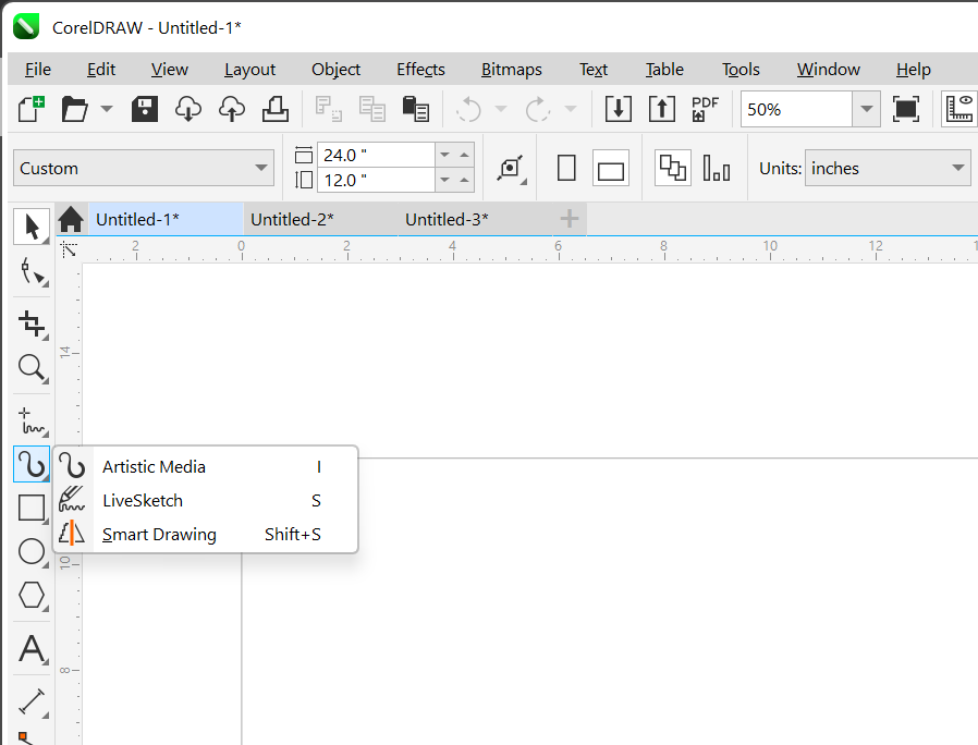
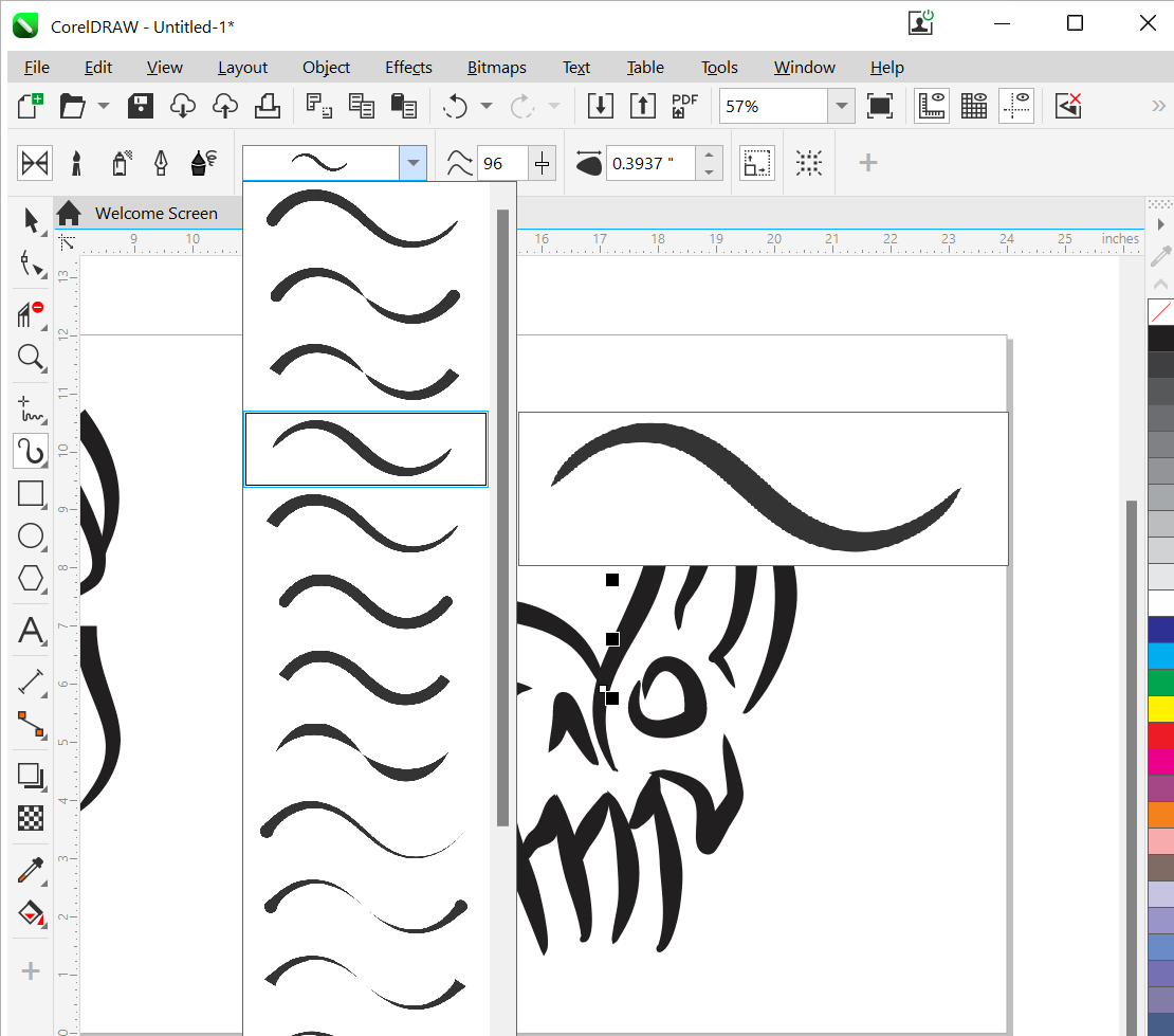
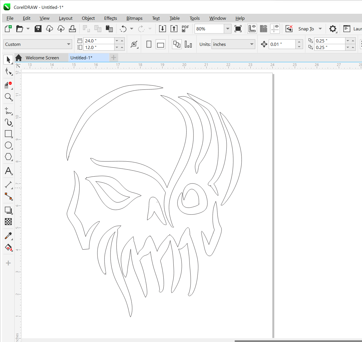
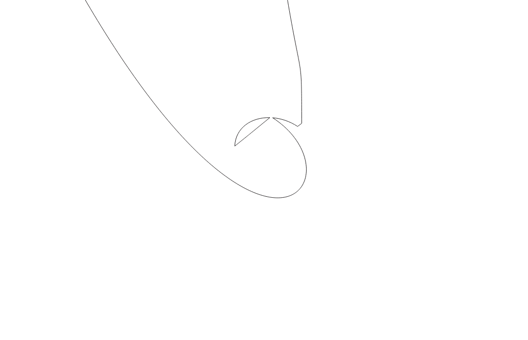
I created two drawings as options to select which one would become a sticker for my skirt. To bring my creative vision to life, I utilized the Artistic Media tool, allowing me to unleash my artistic expression and craft unique designs.
For the first drawing I chose this line:
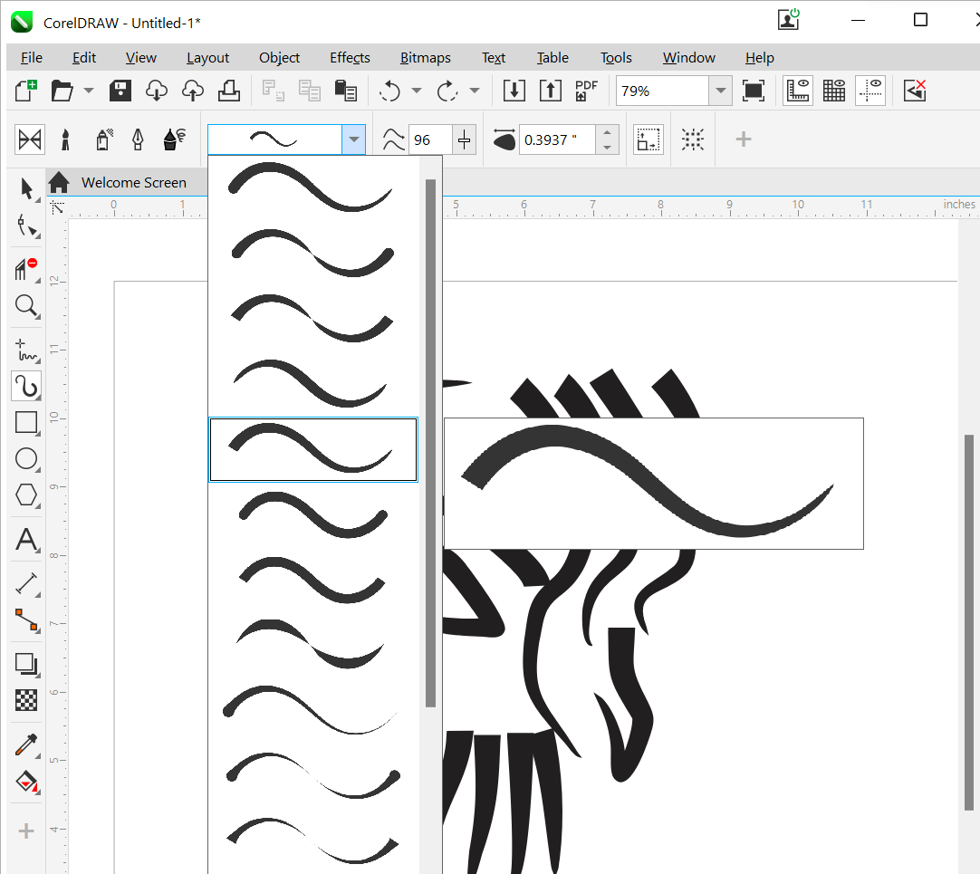
For the second sketch, this line:
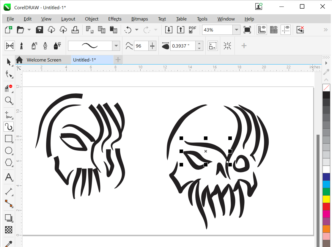
My 2 sketches:
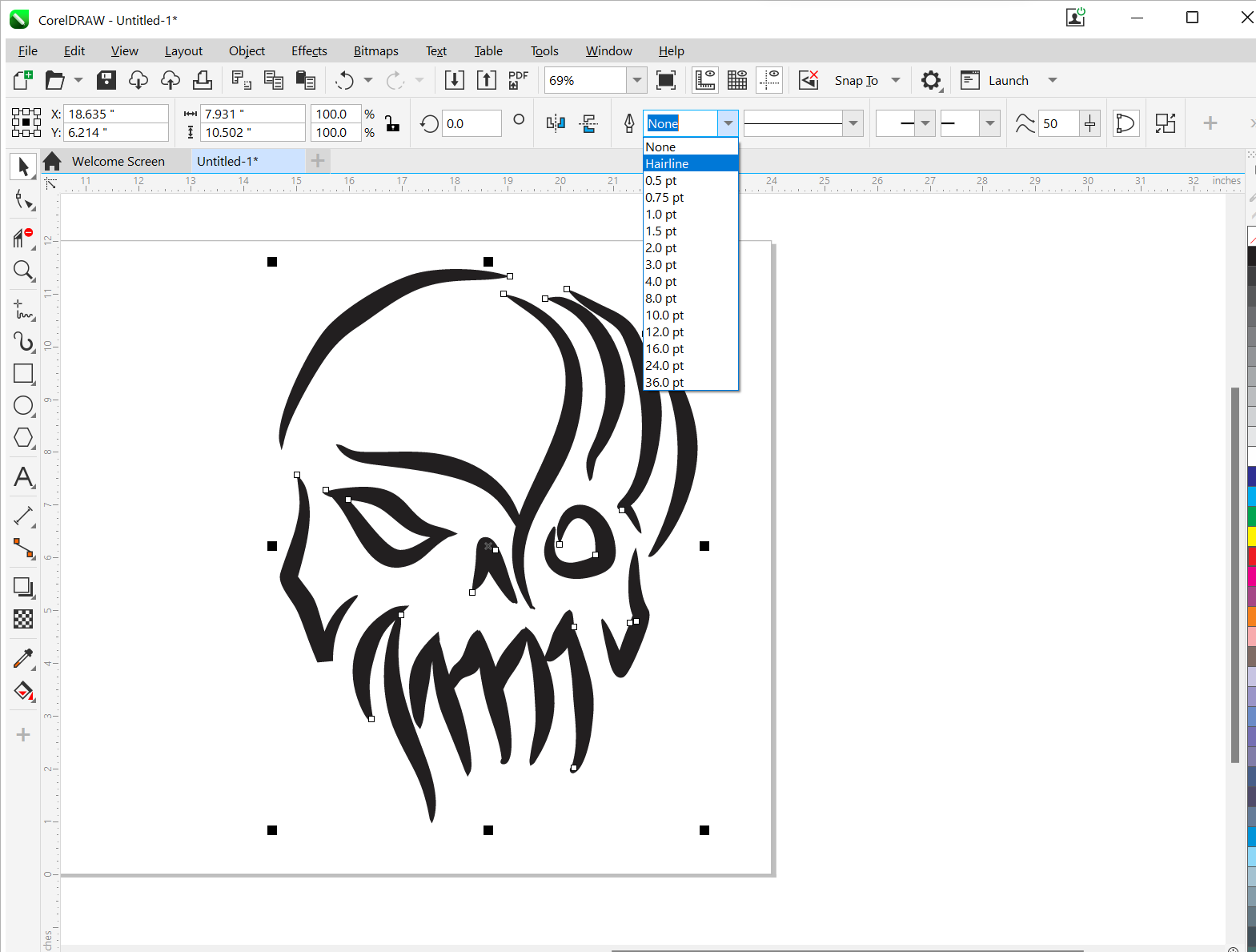
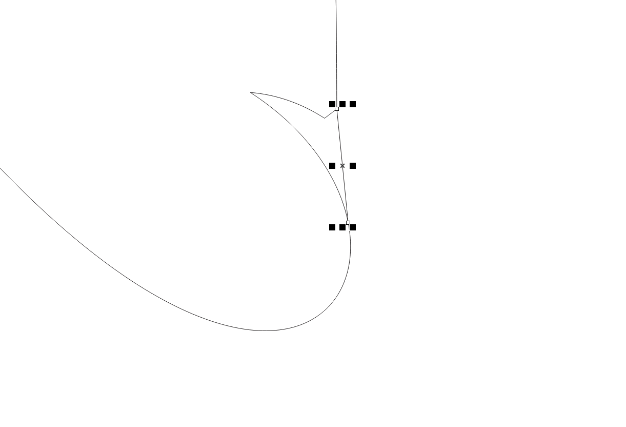
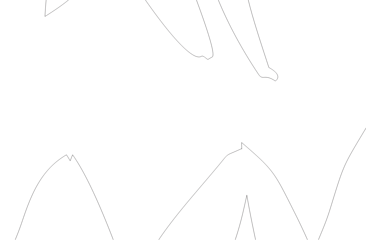
For Vinyl cutting I need to have my lines as a Hairline:
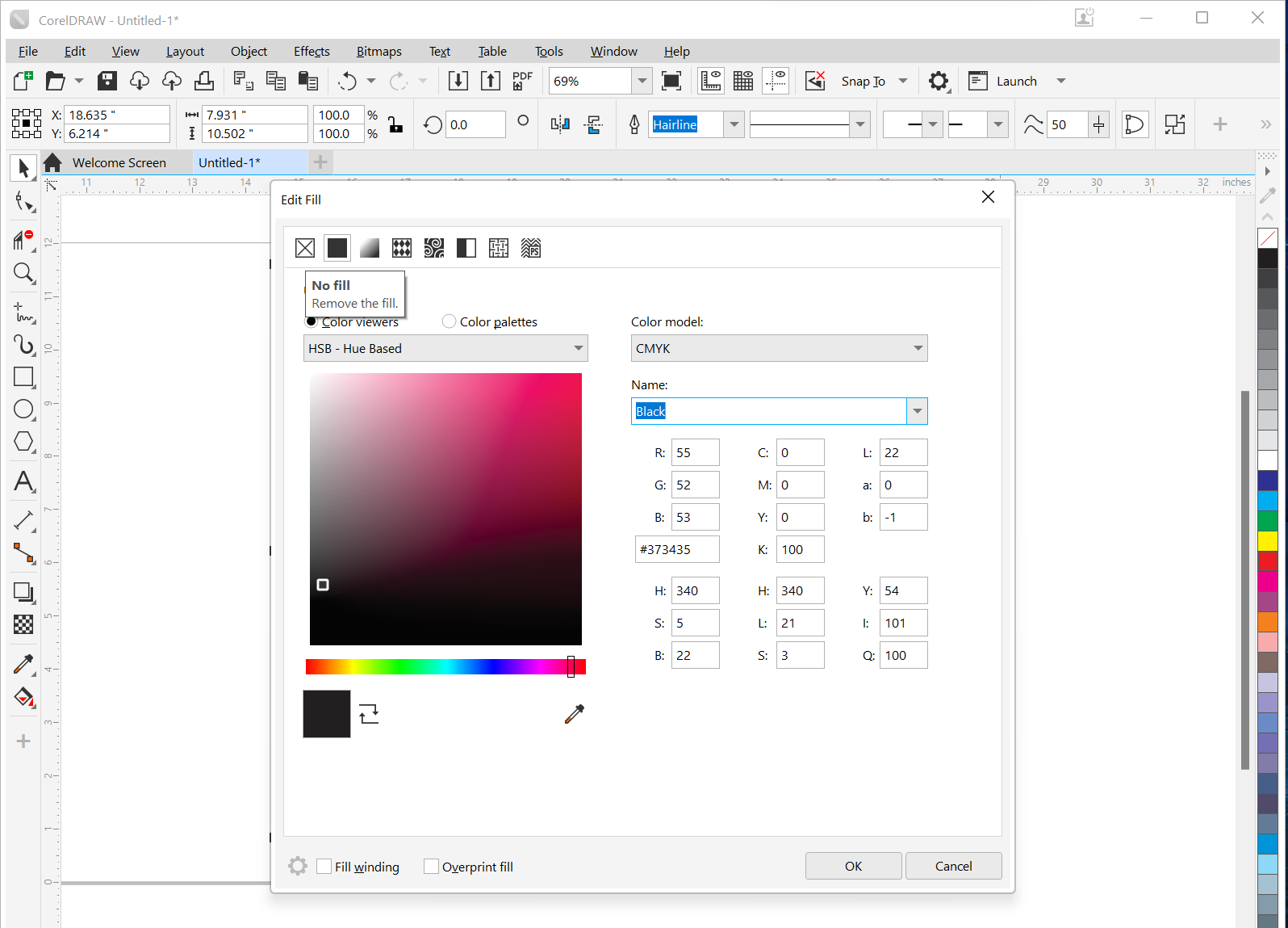
Additionally, I modified the fill of the design by selecting “no fill.”:
That’s what I got:
I have noticed the presence of redundant lines. To rectify this, I will address the issue by adding new lines where necessary and removing the unnecessary ones. This meticulous process will ensure a cleaner and more refined design, eliminating any superfluous elements from the artwork.

My drawing is now fully prepared for the cutting process!
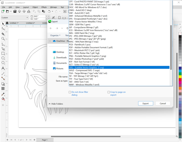
Export as .svg:
From Corel to Inkscape
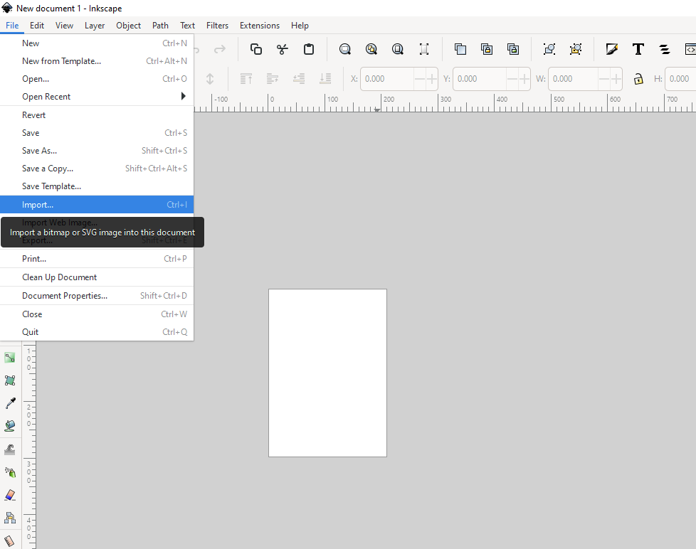
I will utilize Inkscape, the software connected to the vinyl cutter in the Fab Lab, to set up and finalize my drawing before proceeding with the cutting process. Follow my steps to work in Inkscape.
First Import the .svg file:
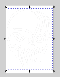
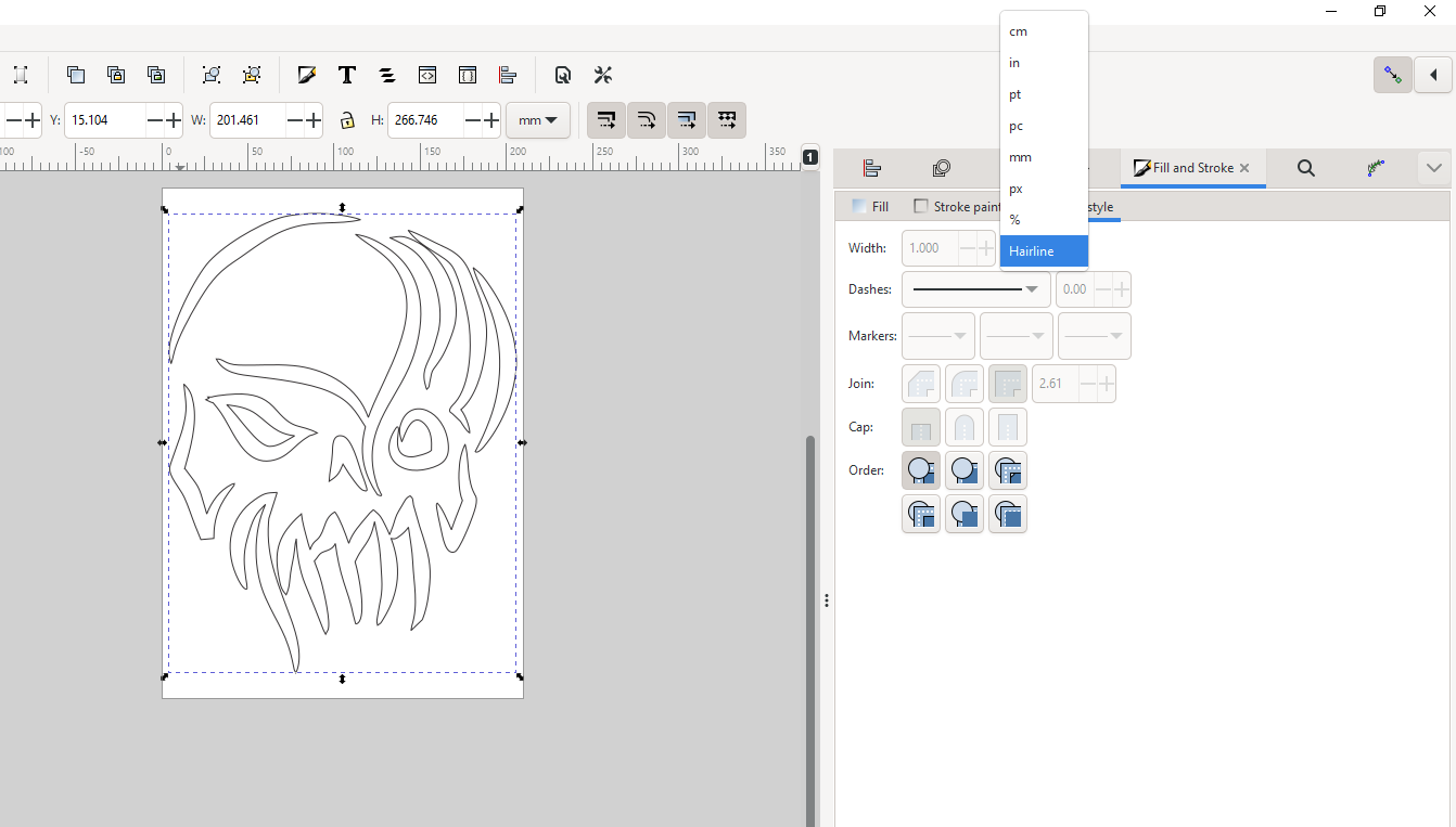
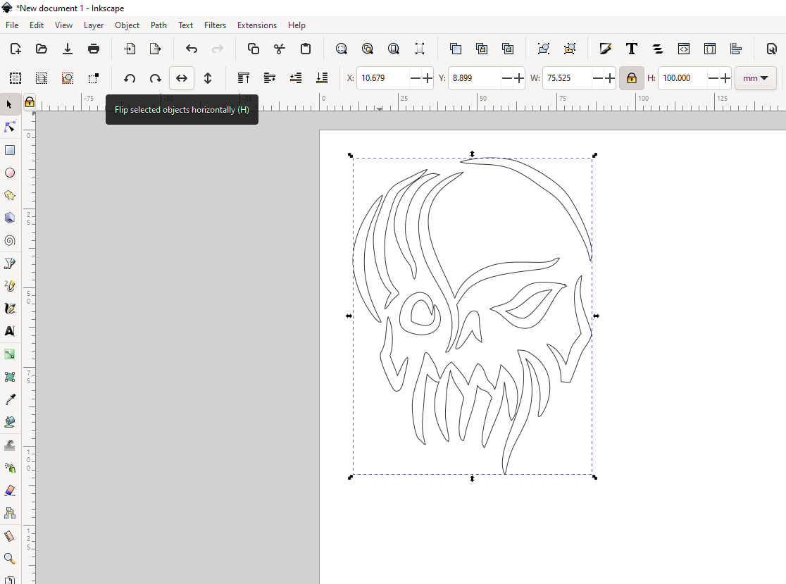
Turn the lines into Hairline:
To have my print on the right direction on my skirt, I needed to mirror the drawing using a tool to flip horizontally.
I positioned and rotated the drawing at the bottom to maximize material utilization. Additionally, I indicated the locations for test cutting.
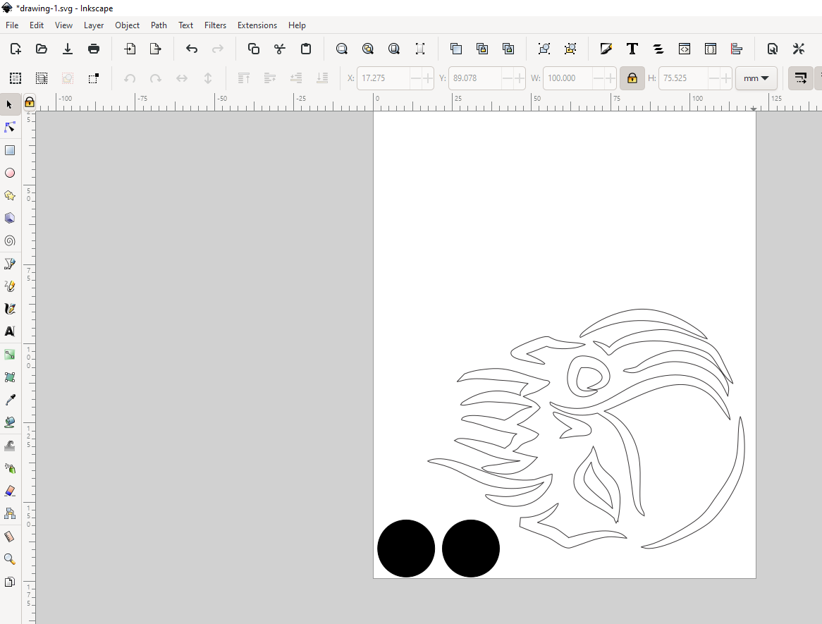
The file is now ready for printing. I have selected the machine for the task.
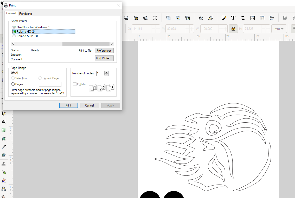
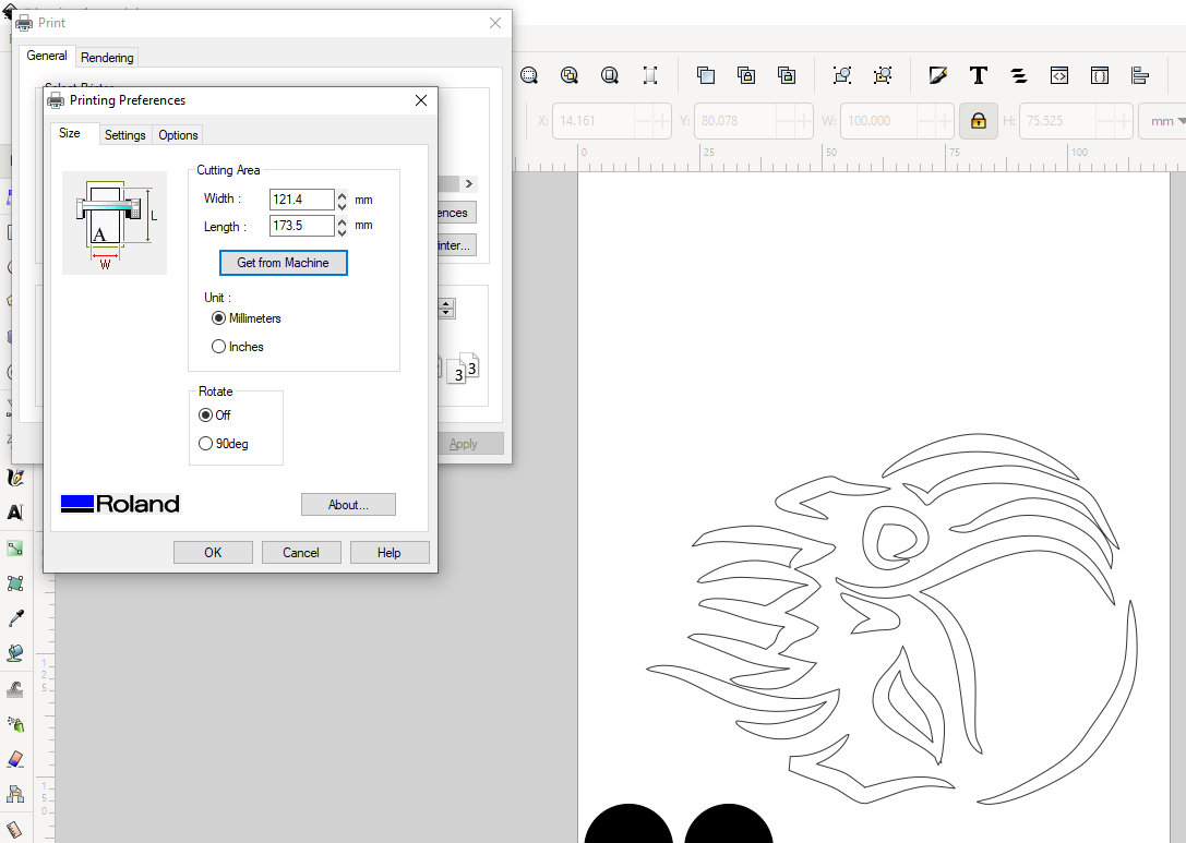
The Get from Machine button allows to retrieve the measurements of the material from the machine directly.
Vinyl cutting and printing
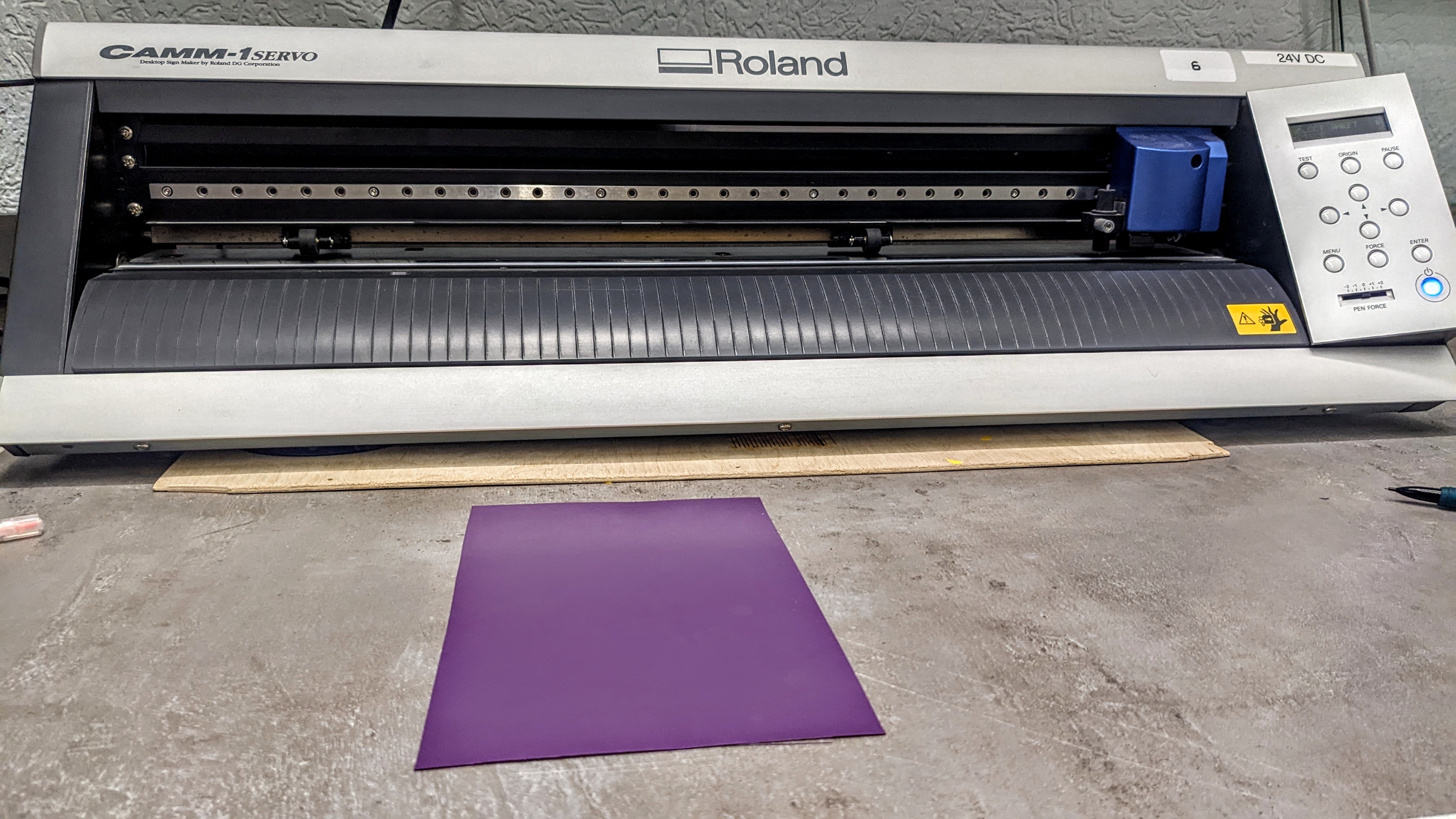
The Vinyl cutter in our Fab Lab is Roland GX-24.
This machine offers precision and versatility for various applications. With its advanced features and reliable performance, it has become a popular choice among professionals and hobbyists alike.
The GX-24 utilizes a digital servo motor, which ensures accurate and smooth cutting of various materials such as vinyl, heat transfer material, and even cardstock. Its maximum cutting width of 24 inches allows for large-scale projects while maintaining precise details.
One of the standout features of the GX-24 is its ability to contour cut printed graphics. By using optical registration marks, the machine can precisely align and cut around printed designs. This capability is particularly useful for creating stickers, decals, and labels with different shapes.
I used a piece of purple vinyl for my skirt print.
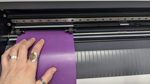
Setup
Now is the time to place the piece of vinyl into the machine. The guide book was very useful for this.
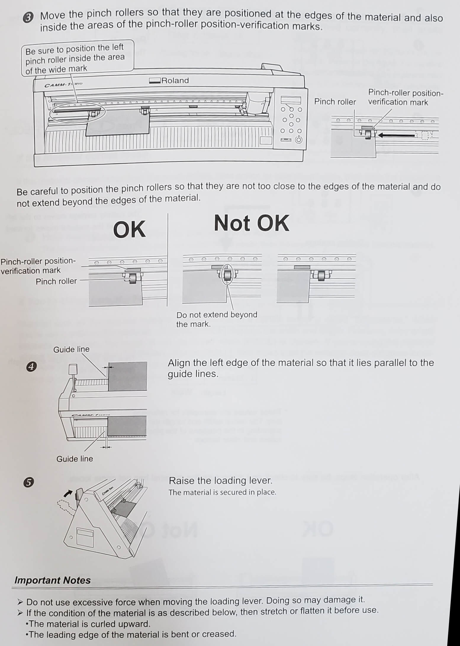
The positioning of the vinyl material inside the cutter is important. When vinyl is rolled, it can develop slight waves or curves that make it difficult to lay flat. To address this, it is crucial to feed the vinyl into the cutter in a direction that is perpendicular to these waves and parallel to adjusting lines.
Unlocking the machine’s versatility, it boasts three distinct feeding modes at your disposal:
-
Piece: The chosen method for my specific endeavor, this option allows me to feed the material in individual pieces, ensuring meticulous precision and customization.
-
Roll: Embracing the ease of continuous operation, the roll feeding option enables seamless cutting by accommodating rolled vinyl, facilitating efficiency for large-scale projects.
-
Edge: A clever choice for seamless edge-to-edge cutting, this feeding mode optimizes the utilization of material by aligning it against the machine’s edge, promising optimal results.
For my purpose, I have embarked on the journey of creativity by opting for the piece feeding mode:
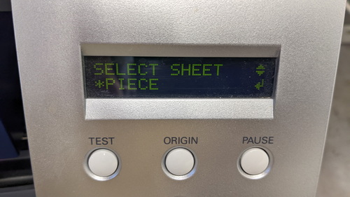
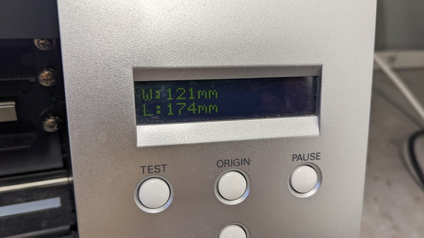
Now the machine automatically measures the size of the material and writes the available size on the display.
This size is different from the physical size of the piece, because the work of the needle, which cuts, is interfered by some parts of the machine in order to use all the space.
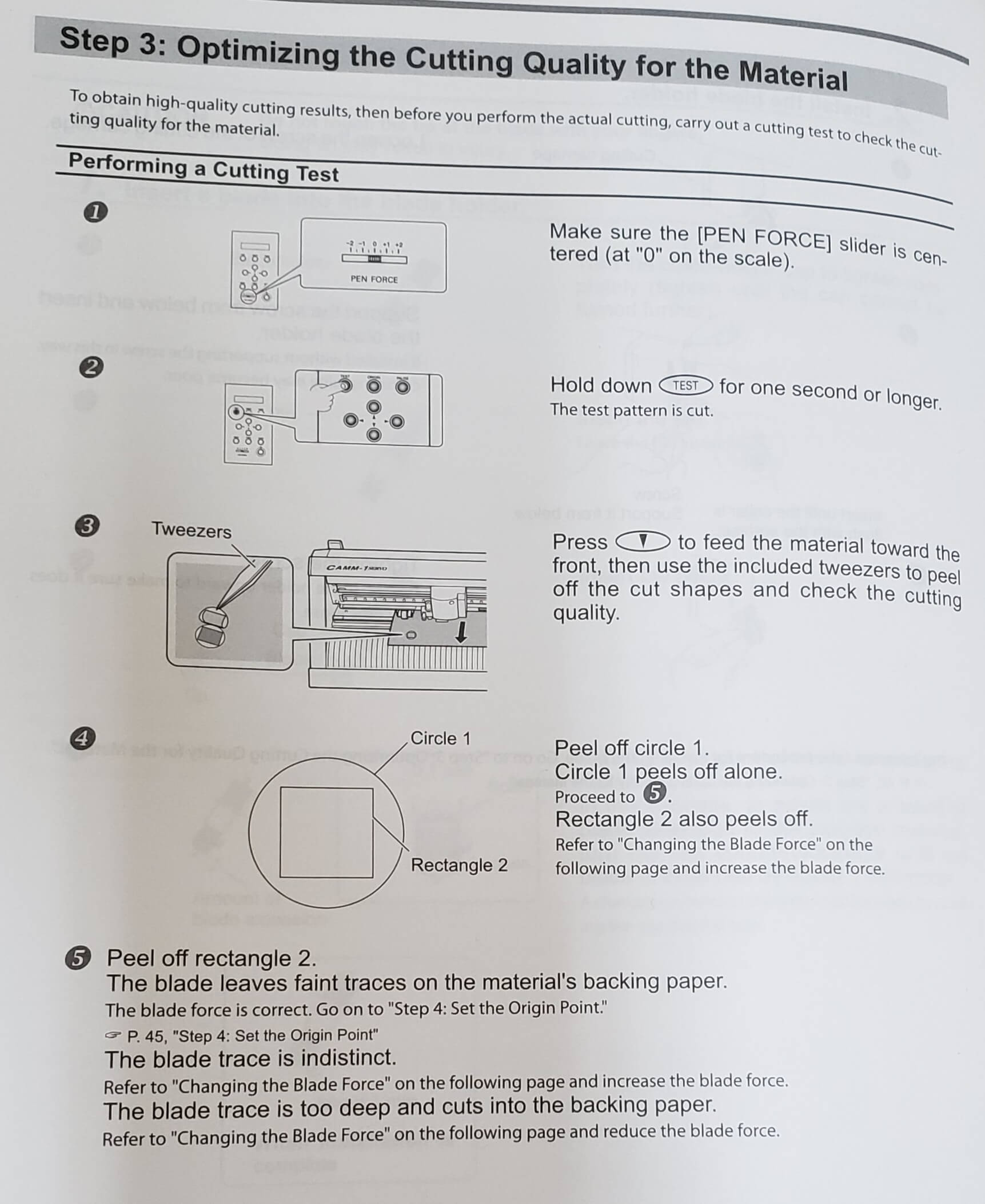
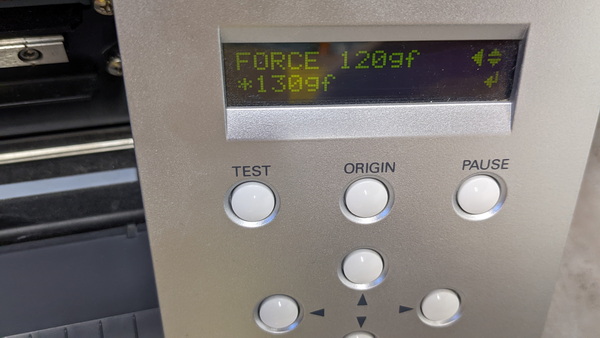
Now, it is essential for us to select the appropriate force value and conduct a test to determine if it is the optimal force required to cut this special vinyl sheet. The qualities of the vinyl sheet, such as thickness, flexibility, and composition, play a significant role in determining the ideal force setting. It’s essential to experiment and conduct tests to find the perfect balance between cutting depth and preserving the integrity of the vinyl. In the manual you can explore the steps:
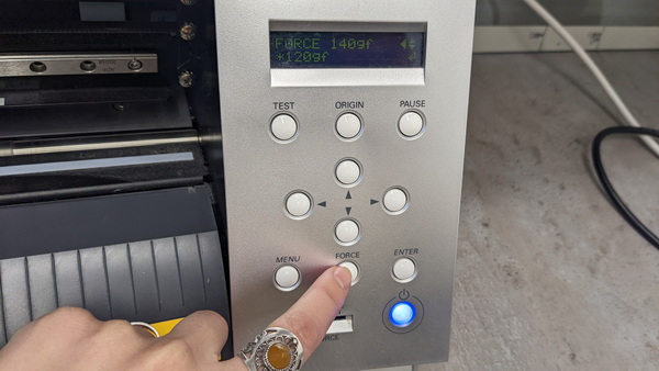
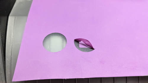
First I setup the Force: 120 gf.
As you can notice, I peel of the rectangle and it seemes to mee to chose the right force for cutting, but I noticed an uneven cutout and it was difficult to detach the rectangle from the circle.
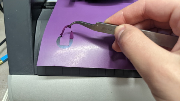
So I changed the Force: 130 gf.
This time, I found the result to be much more satisfying.
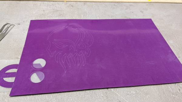
Now it’s time to use the tweezers and remove the bits of vinyl we don’t need.
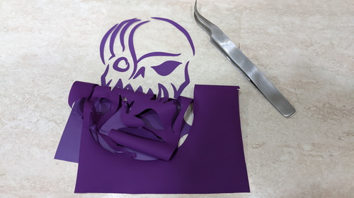
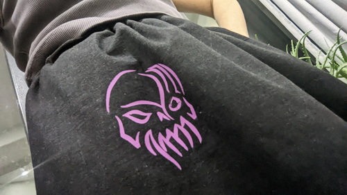
After going through the iron and taking off the transparent layer, I got the desired print on the skirt I made:
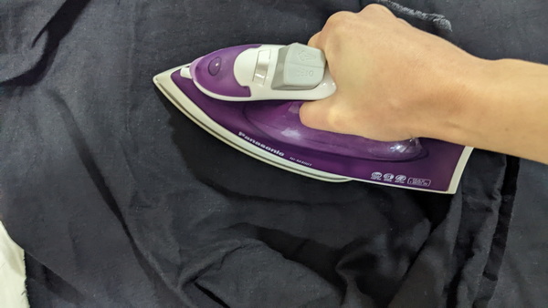
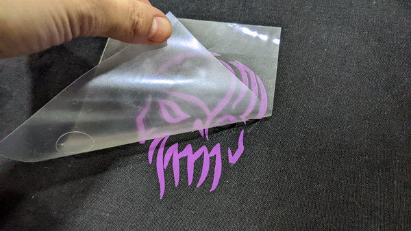
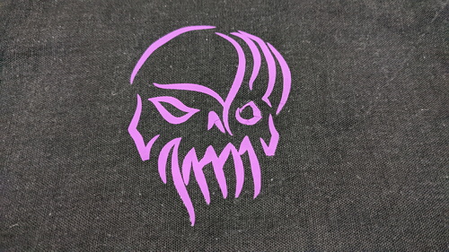
Voila! The rock ‘n’ roll skirt is now ready to be worn.
Conclusion
The week’s assignment on laser and vinyl cutting provided a valuable hands-on learning experience in the field of digital fabrication. By exploring laser cutting techniques, I gained a deeper understanding of how to transform designs into precise and intricate prototypes. The process allowed me to refine my attention to detail, problem-solving skills, and proficiency in FreeCAD software.
Moreover, vinyl cutting introduced me to the world of personalized graphics and signage. Through the creation of custom decals and designs, I discovered the power of visual communication and the importance of precise execution. This assignment expanded my creative capabilities and emphasized the significance of meticulous planning and execution.
This assignment enhanced my skills in laser and vinyl cutting, empowering me to bring my design ideas to life with precision and creativity. I look forward to applying these techniques in future projects and leveraging my newfound expertise to contribute to the field of digital fabrication.
Original files
Laser cut
Vinyl cut