12. Input devices
This week we our focus was on input devices and in particular sensors. Our local instructors pushed us to use I2C enabled sensors. You can find the group work here
Goals
Probe an input device(s)'s analog and digital signals
Document your work on the group work page and reflect on your individual page what you learned
Accomplishment
-
Successfully set up the BMP280 TEMP/Pressure sensor on multiple platforms included the RP2040 board "Fab Xiao"
-
Added color changing LED to sensor code to signal temp changes
-
Attempted to make my own Low Power 3D Hall Sensor with I2C Interface using the Infineon TLE493D-A2B6. reached the limit of my milling machine and had to switch to the BMP280 given time constraint for the week
-
I successfully milled, stuffed and coded a step response sensor based on the one Adrian Torres designed for the Fab Xiao
Infineon TLE493D-A2B6 Low Power 3D Hall Sensor with I2C Interface
You can find the data sheethere.
I read through the decided to use the circuit in the data sheet
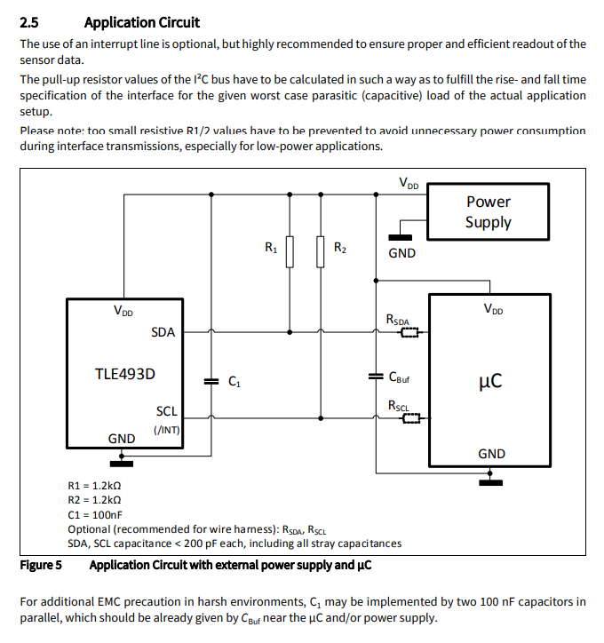
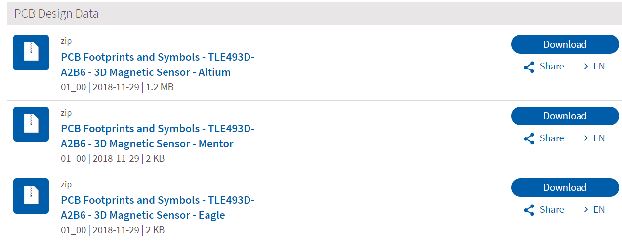
I found the sensor foot print for Eagle and downloaded the library
In eagle I created the circuit from the data sheet
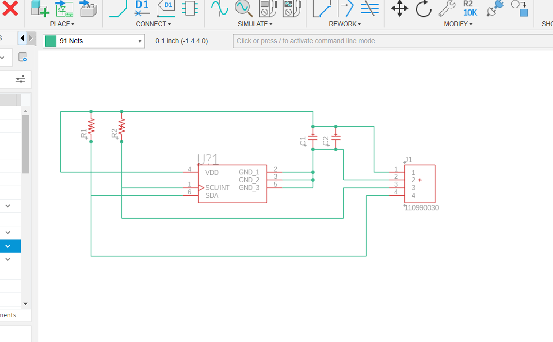
And then the board
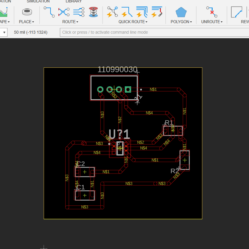
GOt it ready to mill
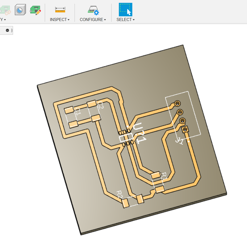
And had to use a 0.2mm bit to mill the board which was the smallest bit I had.
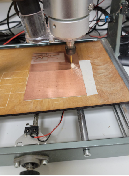
My milling machine requires manual Z calibration and while I got it to mill the size of the connector are so small that a slight off set of the Z access made the pad unsolderable for me given the size.
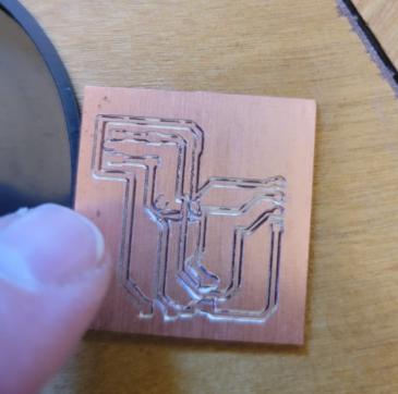
I repeated this a number of times with the same results. At this point I had to make a call if I spend more time on milling or focusing on working with the sensors. As this is input week I decided to move on and use a different sensor we have in the lab
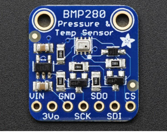
Adafruit BMP280 I2C or SPI Barometric Pressure & Altitude Sensor
As I spent a lot of time on the TLE493D sensor I had to change gears quickly. I decided to the the Adafruit BMP280 Barometric Pressure + Temperature Sensor as it was an I2C enabled sensor we had in the lab.
First of all I found the data sheet here
In the data sheet there is a clear pint out
I quickly set up the connection to the Fab Xiao and loaded the code and opened the serial monitor and ....nothing :(
I did not know if the issue was the board, the code or the sensor.... I decided to step back and start build up into the final solution with the following steps:
- I would test the sensor on an arduino - make sure the code and sensor work
- Get it working with an RP2040 and ensure any code adjustment needed work
- Get it working on the Fab Xiao board
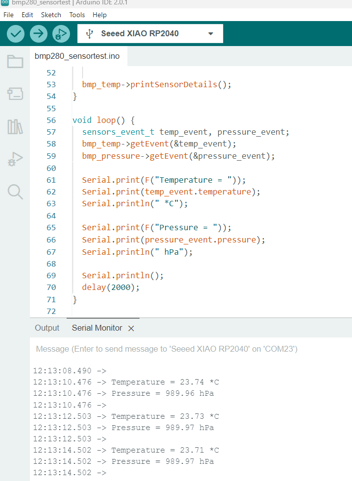
BMP280 and Arduino
I decided to to try it out on an arduino first.
I got it wired up as per the example in the data sheet
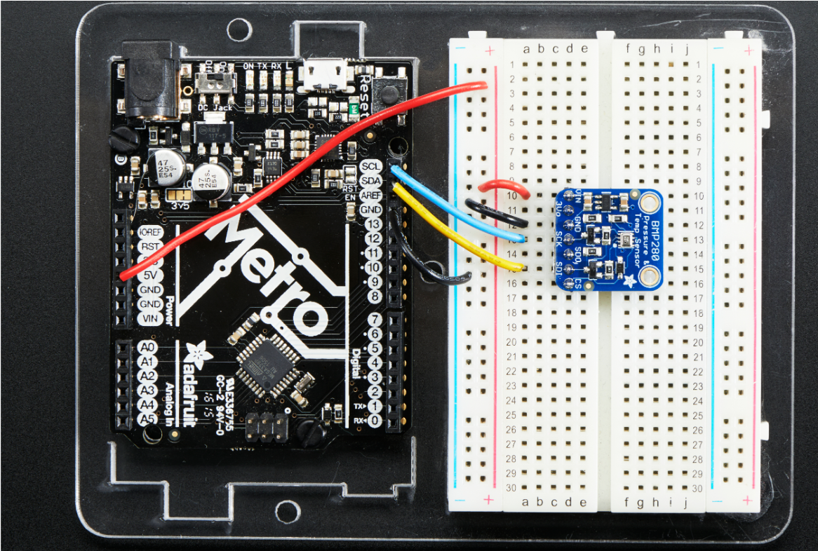
I downloaded the BMP library and ran the example test code
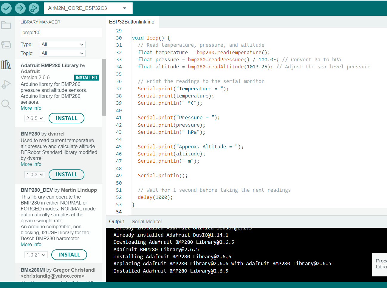
I uploaded the example code
/***************************************************************************
  This is a library for the BMP280 humidity, temperature & pressure sensor
  This example shows how to take Sensor Events instead of direct readings

  Designed specifically to work with the Adafruit BMP280 Breakout
  ----> http://www.adafruit.com/products/2651

  These sensors use I2C or SPI to communicate, 2 or 4 pins are required
  to interface.

  Adafruit invests time and resources providing this open source code,
  please support Adafruit and open-source hardware by purchasing products
  from Adafruit!

  Written by Limor Fried & Kevin Townsend for Adafruit Industries.
  BSD license, all text above must be included in any redistribution
 ***************************************************************************/

#include <Wire.h>
#include <SPI.h>
#include <Adafruit_BMP280.h>

Adafruit_BMP280 bmp; // use I2C interface
Adafruit_Sensor *bmp_temp = bmp.getTemperatureSensor();
Adafruit_Sensor *bmp_pressure = bmp.getPressureSensor();

void setup() {
  Serial.begin(9600);
  while ( !Serial ) delay(100);   // wait for native usb
  Serial.println(F("BMP280 Sensor event test"));

  unsigned status;
  //status = bmp.begin(BMP280_ADDRESS_ALT, BMP280_CHIPID);
  status = bmp.begin();
  if (!status) {
    Serial.println(F("Could not find a valid BMP280 sensor, check wiring or "
                      "try a different address!"));
    Serial.print("SensorID was: 0x"); Serial.println(bmp.sensorID(),16);
    Serial.print("        ID of 0xFF probably means a bad address, a BMP 180 or BMP 085\n");
    Serial.print("   ID of 0x56-0x58 represents a BMP 280,\n");
    Serial.print("        ID of 0x60 represents a BME 280.\n");
    Serial.print("        ID of 0x61 represents a BME 680.\n");
    while (1) delay(10);
  }

  /* Default settings from datasheet. */
  bmp.setSampling(Adafruit_BMP280::MODE_NORMAL,     /* Operating Mode. */
                  Adafruit_BMP280::SAMPLING_X2,     /* Temp. oversampling */
                  Adafruit_BMP280::SAMPLING_X16,    /* Pressure oversampling */
                  Adafruit_BMP280::FILTER_X16,      /* Filtering. */
                  Adafruit_BMP280::STANDBY_MS_500); /* Standby time. */

  bmp_temp->printSensorDetails();
}

void loop() {
  sensors_event_t temp_event, pressure_event;
  bmp_temp->getEvent(&temp_event);
  bmp_pressure->getEvent(&pressure_event);

  Serial.print(F("Temperature = "));
  Serial.print(temp_event.temperature);
  Serial.println(" *C");

  Serial.print(F("Pressure = "));
  Serial.print(pressure_event.pressure);
  Serial.println(" hPa");

  Serial.println();
  delay(2000);
}
I got the following error
16:19:39.376 -> BMP280 Sensor event test
16:19:40.949 -> Could not find a valid BMP280 sensor, check wiring or try a different address!
16:19:40.997 -> SensorID was: 0x0
16:19:41.030 -> ID of 0xFF probably means a bad address, a BMP 180 or BMP 085
16:19:41.096 -> ID of 0x56-0x58 represents a BMP 280,
16:19:41.128 -> ID of 0x60 represents a BME 280.
16:19:41.193 -> ID of 0x61 represents a BME 680.
16:20:11.940 -> BMP280 Sensor event test
16:20:11.974 -> Could not find a valid BMP280 sensor, check wiring or try a different address!
I reinspected my wiring and while it matched the once for the data sheet I did notice that I had put the I2C wires into the wrong place in the Arduino .... a quick correction and we are off to the races.
16:20:12.236 -> ID of 0x61 represents a BME 680.
16:20:47.963 -> BMP280 Sensor event test
16:20:48.086 -> ------------------------------------
16:20:48.119 -> Sensor: BMP280
16:20:48.119 -> Type: Ambient Temp (C)
16:20:48.185 -> Driver Ver: 1
16:20:48.185 -> Unique ID: 280
16:20:48.217 -> Min Value: -40.00
16:20:48.217 -> Max Value: 85.00
16:20:48.250 -> Resolution: 0.01
16:20:48.283 -> ------------------------------------
16:20:48.316 ->
16:20:48.316 -> Temperature = 27.73 *C
16:20:48.349 -> Pressure = 991.60 hPa
16:20:48.349 ->
16:20:50.315 -> Temperature = 27.67 *C
16:20:50.315 -> Pressure = 991.53 hPa
No I wanted to check the temp and so start blowing hot air on the sensor and quickly say the temp start to climb
16:35:41.981 -> Temperature = 23.54 *C
16:35:41.981 -> Pressure = 991.40 hPa
16:35:42.041 ->
16:35:43.962 -> Temperature = 23.54 *C
16:35:43.995 -> Pressure = 991.41 hPa
16:35:44.037 ->
16:35:45.998 -> Temperature = 23.53 *C
16:35:45.998 -> Pressure = 991.42 hPa
16:35:46.037 ->
16:35:47.984 -> Temperature = 24.20 *C
16:35:48.034 -> Pressure = 991.42 hPa
16:35:48.076 ->
16:35:50.007 -> Temperature = 25.51 *C
16:35:50.007 -> Pressure = 991.43 hPa
16:35:50.049 ->
16:35:51.982 -> Temperature = 26.59 *C
16:35:52.014 -> Pressure = 991.43 hPa
16:35:52.060 ->
16:35:53.994 -> Temperature = 27.44 *C
16:35:54.025 -> Pressure = 991.48 hPa
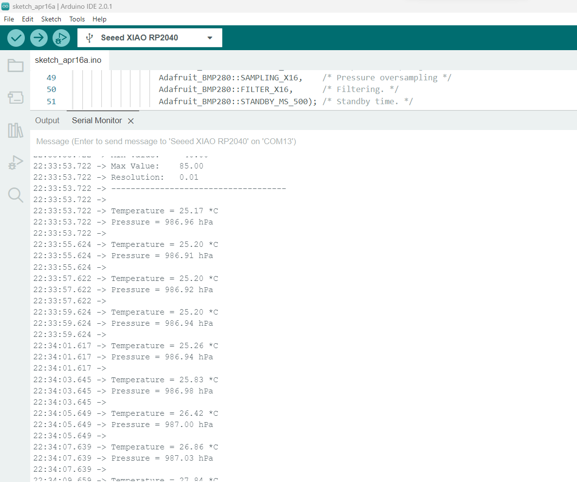
BMP280 moving to the RP2040
I set up the basic connection with the using the following pinout
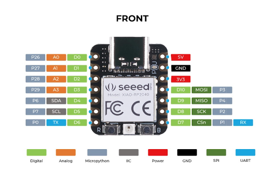
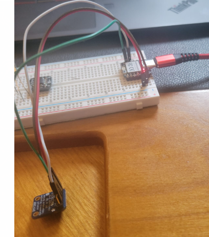
Made the connections to the sensor
All I see is an empty serial monitor..... some digging around and I found the issue
When I loaded up the RP2040 with the code in bootloader mode it was running off of port 6 in my PC. After the board restarts it disconnect with Port 6 and had a new port.
Once I went it and selected the new port (13) the connection was made and the serial monitor started to work.
And we are live:
BMP280 and Fab Xiao
I wanted to hook up the sensor the to board I made based on the fab xiao. It was pretty straight forward following the same code I used with the the RP2040 stand alone
The pinout for the board is (big thank you to Adrian Torres)
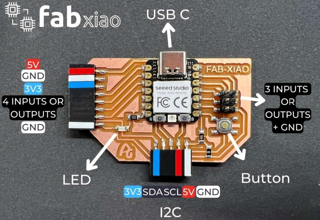
You can find more about the Fabxiao here
I hooked up the sensor
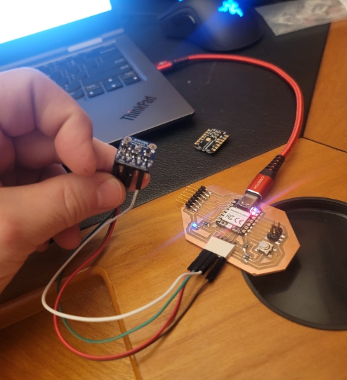
and here you go as I blow hot air the temp goes up:
Now I decided to add some code to make the onboard RGB color change based on the temp reading using on the RP2040 Xiao onboard neopixle as follows:
#include <Wire.h>
#include <SPI.h>
#include <Adafruit_BMP280.h>
#include <Adafruit_NeoPixel.h>

int Power = 11;
int PIN = 12;
#define NUMPIXELS 1

Adafruit_BMP280 bmp; // use I2C interface
Adafruit_Sensor *bmp_temp = bmp.getTemperatureSensor();
Adafruit_Sensor *bmp_pressure = bmp.getPressureSensor();
Adafruit_NeoPixel pixels(NUMPIXELS, PIN, NEO_GRB + NEO_KHZ800);

void setup() {
  Serial.begin(9600);
  while ( !Serial ) delay(100);   // wait for native usb
  Serial.println(F("BMP280 Sensor event test"));

  unsigned status;
  status = bmp.begin();
  if (!status) {
    Serial.println(F("Could not find a valid BMP280 sensor, check wiring or "
                      "try a different address!"));
    while (1) delay(10);
  }

  /* Default settings from datasheet. */
  bmp.setSampling(Adafruit_BMP280::MODE_NORMAL,
                  Adafruit_BMP280::SAMPLING_X2,
                  Adafruit_BMP280::SAMPLING_X16,
                  Adafruit_BMP280::FILTER_X16,
                  Adafruit_BMP280::STANDBY_MS_500);

  bmp_temp->printSensorDetails();

  pixels.begin();
  pinMode(Power,OUTPUT);
  digitalWrite(Power, HIGH);
}

void loop() {
  sensors_event_t temp_event, pressure_event;
  bmp_temp->getEvent(&temp_event);
  bmp_pressure->getEvent(&pressure_event);

  Serial.print(F("Temperature = "));
  Serial.print(temp_event.temperature);
  Serial.println(" *C");

 // pixels.clear();


  if (temp_event.temperature < 26) {
  pixels.setPixelColor(0, pixels.Color(15, 25, 205));
  } else if (temp_event.temperature >= 30) {
  pixels.setPixelColor(0, pixels.Color(233, 242, 205));
  } else {
  pixels.setPixelColor(0, pixels.Color(233, 23, 23));

  }
  pixels.show();


  Serial.print(F("Pressure = "));
  Serial.print(pressure_event.pressure);
  Serial.println(" hPa");

  Serial.println();
  delay(2000);
}
To show case it in the video I code an ice pack and a cup of hot water. You can see the serial monitor in the background
Step response sensor
I ended up have a little time on Tueday and did not want to give up on milling my own sensor board and was impressed with the Prof Gershenfeld's description of a step response sensor and so decided to try my hand at making one of these.
I decided to focus on the Step response design that Adrian Torres developed for the Fab Xiao that you can find here
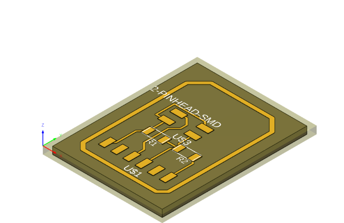
I downloaded the eagle design from his site here and uploaded to fusion
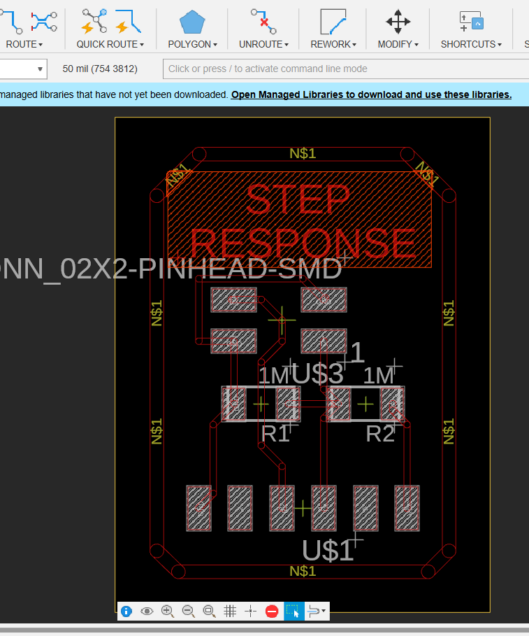
I then created the 3D board and made the milling paths
I proceeded to make the board following the example he had on the site

I have the board and layed out the components
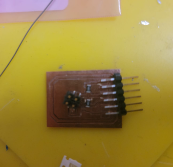
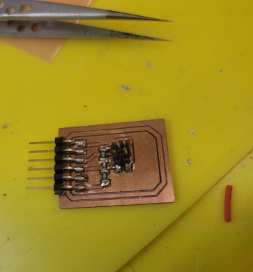
Stuffing and soldering
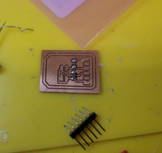
We are ready to go
I improvised electrodes from some scap PCBs
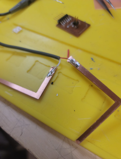
Here we are set up and ready to go.
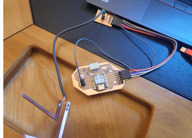
I took the example code from Adrian Torres here and added the same RGB color changing approach I used with the BMP280
#include <Adafruit_NeoPixel.h>

int Power = 11;
int PIN = 12;
#define NUMPIXELS 1

long result;   //variable for the result of the tx_rx measurement.
int analog_pin = 27; //  GPIO 27 of the XIA0 RP2040
int tx_pin = 28;  //     GPIO 28 of the XIAO RP2040
Adafruit_NeoPixel pixels(NUMPIXELS, PIN, NEO_GRB + NEO_KHZ800);


void setup() {
pinMode(tx_pin,OUTPUT);      //Pin 2 provides the voltage step
Serial.begin(115200);
pixels.begin();
  pinMode(Power,OUTPUT);
  digitalWrite(Power, HIGH);

}


long tx_rx(){         //Function to execute rx_tx algorithm and return a value
                      //that depends on coupling of two electrodes.
                      //Value returned is a long integer.
  int read_high;
  int read_low;
  int diff;
  long int sum;
  int N_samples = 100;    //Number of samples to take.  Larger number slows it down, but reduces scatter.

  sum = 0;

  for (int i = 0; i < N_samples; i++){
   digitalWrite(tx_pin,HIGH);              //Step the voltage high on conductor 1.
   read_high = analogRead(analog_pin);        //Measure response of conductor 2.
   delayMicroseconds(100);            //Delay to reach steady state.
   digitalWrite(tx_pin,LOW);               //Step the voltage to zero on conductor 1.
   read_low = analogRead(analog_pin);         //Measure response of conductor 2.
   diff = read_high - read_low;       //desired answer is the difference between high and low.
 sum += diff;                       //Sums up N_samples of these measurements.
 }
  return sum;
}                         //End of tx_rx function.


void loop() {

result = tx_rx();
result = map(result, 17000, 23000, 0, 1024);  //I recommend mapping the values of the two copper plates, it will depend on their size
Serial.println(result);

  if (result < 3000) {
  pixels.setPixelColor(0, pixels.Color(15, 25, 205));
  } else if (result >= 5000) {
  pixels.setPixelColor(0, pixels.Color(233, 242, 205));
  } else {
  pixels.setPixelColor(0, pixels.Color(233, 23, 23));

  }
  pixels.show();

delay(100);
}
And here you can see it in action
You can find the base BMP280 sensor test code here
You can find the BMP280 RGB color changing code here
You can find the step response RGB color changing code here
You can find the files for TLE493D board milling here
You can find the files for step response board milling here