0. Fab Academy prep
In the weeks leading to the start of Fab Academy we had weekly pre academy training. This was great experience both freshing up some old skills, picking up some new ones and starting to learn how to document.
Accomplishments
-
Learned basic surface mount soldering
-
Programed a Tiny412 for the first time
-
Built a mini Prusa 3D printer
-
Got a basic understanding of documentation
-
Milled my first PCB board
-
Gain some basic fusion 360 knowledge
Surface mount soldering
In the first session of the fab academy pre-work we were introduced to surface mount soldering. I had past experiences with through hole soldering and while I was no expert, I was very comfortable. This comfort was quickly replaced with squinting and concern as I barley was able to see the components we were tasked with surface mount soldering.
After a quick instruction we dove right in and quickly I realized that it is time for a new prescription for my glasses. However, with the help of the digital microscope I managed to get my first component down!!!
I watched a number of online videos showing techniques but none of them were that helpful and so I will not post a link. The key takeaway from the first video was "try different approaches and see what works for you"
I followed this advice and tried tweezers, solder past, hot plate etc. and I settled down on a 5 step approach that worked.
- Put some flux down
- Add solder to one pad
- Position component and solder in leg on pad that already has solder
- Use the soldering iron to lock in the one on the pad with solder
- Solder other legs
!! magnifying glasses/electronic microscope are very very important
We worked through mounting a 412 on a board
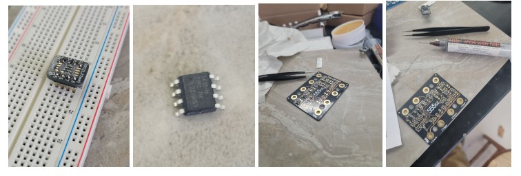
Off I went working through the rest of the 555 practice board.
After the first few resistor were in place got my multimeter out to check if resistors were positioned well and so far so good….. 2 hours later I got all the components down with little problem, however, I managed to get some solder into the connection bolts which made testing a little more complicated. After a little clean up…..success a blinking red light!
I did chuckle to myself as the factories I ran as President for Lenovo Latin America had 4 robotic SMD lines for board manufacturing. It was much easier to watch the robots then trying to nail down this components myself
Learning CAD - fusion 360
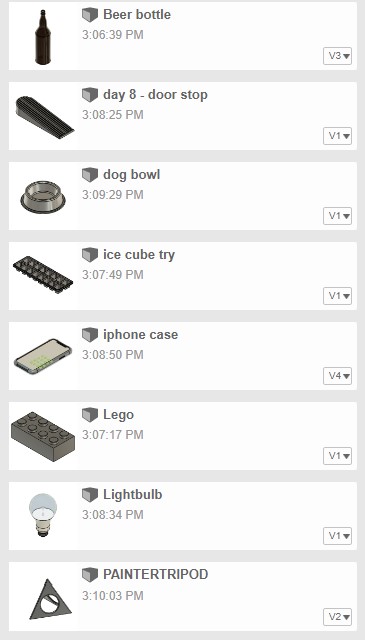
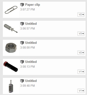
I had a little expreinace for CAD with limited use of TinkerCAD. Tom Dubick shared the Kevin Kennedy "Learning Fusion 360 in 30 days" Youtube playlist.
He is very good teacher and I have learned a lot working through his different videos. Here are some examples of the models I made:
|  |
|  |
|
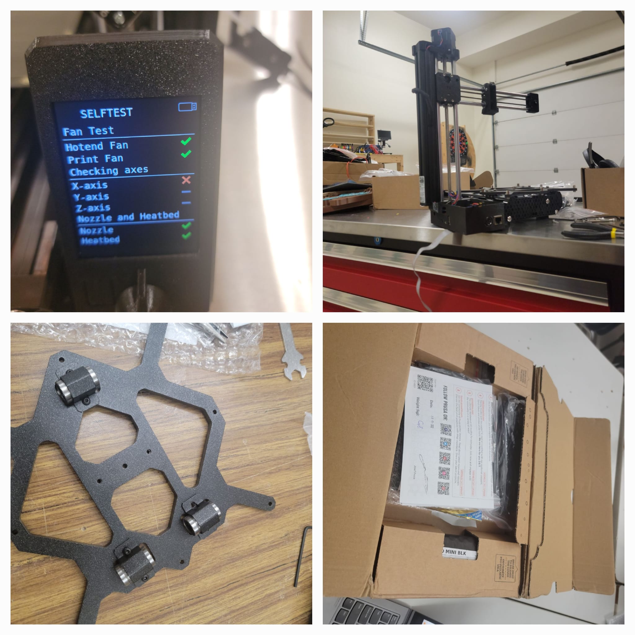
Building 3d Printer - Prusa mini
Next we tackeled building a Pursa mini. This project was pretty straight forward and I just followed instruction.
The challange enountered is that the final self test the X Axis failed.
A quick search found that the tension on the x belt is the likley issue and after a quick adjustment every passed and first print was on the way
Intro to the 412 - Blink
Today's session was all about ATTinty 412 using arduino IDE and JTAG. .
Step 1: IDE SET UP was to get JTAG set up in our IDEs, 20min into this process, I figured out that I had IDE 2.0 and needed IDE 1.8
1.1 Install Arduino IDE 1.8
You can find it at https://www.arduino.cc/en/software/OldSoftwareReleases
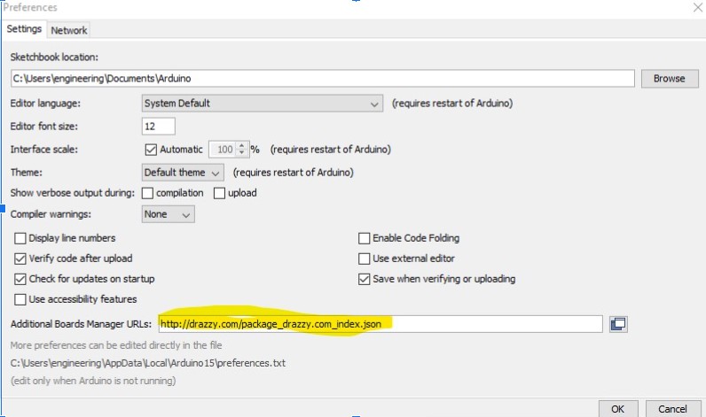
1.2: Add board to the board manager but pasting in link below
http://drazzy.com/package_drazzy.com_index.json
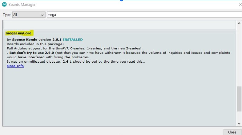
1. 3: Add the ATtiny mega board pack to board manager
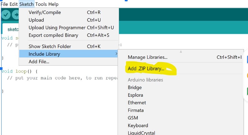
1.4) Add JTAG to library
Add  jtag2udpi library by downloading pack
Pulled the zipped folder out of downloaded file (remove master form name)
Include zipped folder into the library
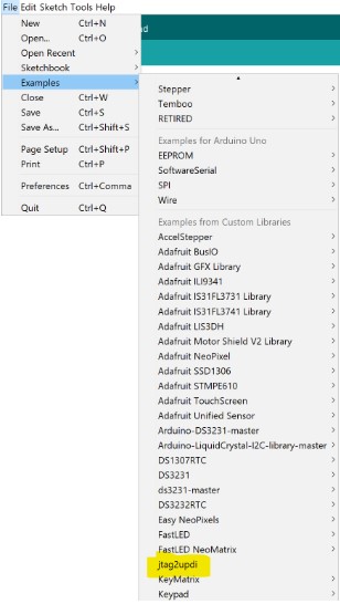
1.5) Open JTAG code and upload Ardunio Uno
1.6) Connect Uno board UDPI leg (6) to connect to UDPI leg on Tiny412 (6)
Ready to upload my first sketch

Another 20min and I am up and running!!
Step 2 - OUTPUT! get blink to on the ATTiny - a quick adjustment to the code based on the pinout map and we were up and running. This went over very smoothly and we had light!
I got the blink example sketch, a quick change to the code to use pin 2 and we are off to the races
Void setup() {
  // initialize digital pin LED_BUILTIN as an output.

  pinMode(2, OUTPUT);} // the loop function runs over and over again forever

void loop() {

  digitalWrite(2, HIGH);   // turn the LED on (HIGH is the voltage level)

  delay(500);                       // wait for a second

  digitalWrite(2, LOW);    // turn the LED off by making the voltage LOW

  delay(500);                       // wait for a second
}
Intro to the 412 - Input - Button
Step 3 - INPUT! Get a button press to input a “HIGH” reading and use a simple IF statement to have another pin to turn on a led…..
*void setup()

{ pinMode(1,INPUT);

pinMode(2,OUTPUT);

}


void loop ()

{   int button = LOW;

   button = digitalRead(1);

  if (button == HIGH) { digitalWrite(2,HIGH); } else {digitalWrite(2,LOW); }}
Led turned on no matter what I did :(. It was just constantly on.....time to troubleshoot
-
Code: First thing i set out to check code - I was sure I had the code right and even refreshed myself on the IF statement but still no go. Big thank you to my classmate Adam D. who reminded me the difference between = and ==..code issue solved but still noy joy...red light is constantly on
-
Wiring: I inspected the wiring 3 times - and it all seemed in place
-
Output: Decided to check my output pin code/set up - I disconnected the button and uploaded a sketch that only turned on led by setting pin 2 to HIGH / then uploaded another sketch with PIN 2 set to LOW. Led turn on + turned off--> we are good on output. I uploaded the original code still no joy the light was on all the time not only when I pressed the button
void setup()
{ pinMode(2,OUTPUT); }


void loop ()
{ digitalWrite(2,HIGH);}


And then


void setup()
{ pinMode(2,OUTPUT); }


void loop ()
{ digitalWrite(2,Low);}
Input: I was pretty sure all that was left was the input code and/or wiring - Pulled out the multimeter and started testing the connection and the button and ---> turns out the button was defective. A quick component replacement and we were off the the races

Intro to the 412 - Input - Photo resistor
In today's session we are going to use analogRead and AnalogWrite commands.\
We read the value from the Photoresistor and then use that value to drive the brightness of an LED.
One major roadblock is the value difference between LED brightness 0-255 and the reading from the Photo resistor 0-1023.
I used the command map(x, v1,v2,v3,v4) which returns the relative value from x in the range of V1-V2 from the range of V2-V4.
So the code looks like:
void setup()

{

  pinMode(2, INPUT);

  pinMode(3, OUTPUT);

}


void loop()

{

  int x;

  x = analogRead(2);

 analogWrite(3,map(x,0,1000,0,255));


}
Quick set up the on the breadboard having
Photoresistor feed pin 2 (leg 4) - can not forget the 10K pulldown resistor between the photoresistor and the ground
Led lights up from pin 3 (leg 5) adding a 330 resistor to ground
And we are off to the races
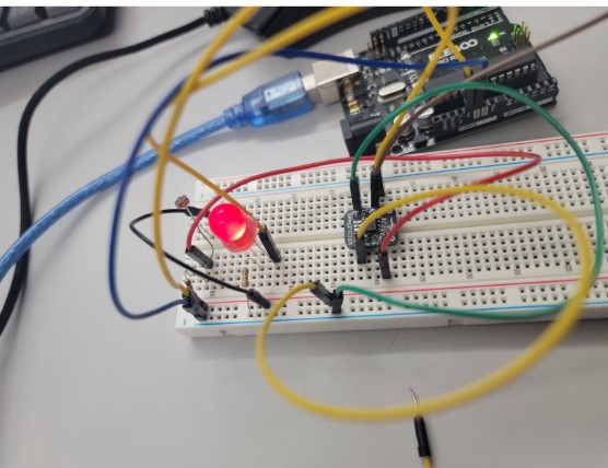
Here is the circuit in action

Milling our first board - blinking 412
We started learning how to mill. I was very excited for this one as it has long been a goal of mine. Mr. Dubick explained the workflow that you can find below:
INSERT WORKFLOW LINK
Then provided us with the files
https://drive.google.com/drive/u/2/folders/1a4XhhFa9FCj9YJwBPnYA_2pSD5SITNcf
And we were off to mill our own board.
Problem 1 - My first attempt failed as I did not remember to change out the bit from a 1/32 to 1/64
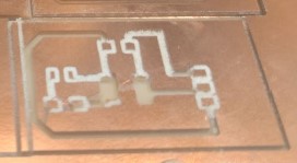
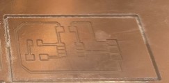
Should look like:
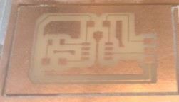 But looked like:
Solution (or so i thought) - change the milling bit
Problem 2 - bit broke as I only changed the bit physically and did not recalibrate the milling machine to the new bit.
`` Solution - press the change tool button at the top right and follow direction …..
Video of the milling process:

And we now have a milled board.
I collected the parts needed Capacitor (uf) 330 resistor LED 412 chip Connectors
Good time to test out my SMT soldering skills.
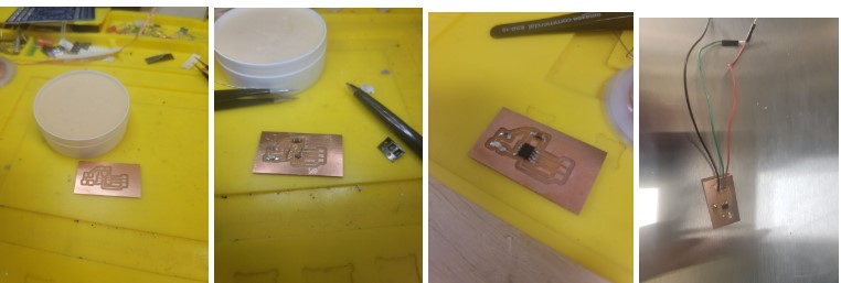
Took me a little time to figure out which side was the ground on the LED - luckily my SMT soldering practice kit had a guide.
Got my arduino IDE fired up and sketch set up
 void setup() {

  // initialize digital pin LED_BUILTIN as an output.

  pinMode (2, OUTPUT);
}

// the loop function runs over and over again forever

void loop() {

  digitalWrite(2, HIGH);   // turn the LED on (HIGH is the voltage level)

  delay(1000);                       // wait for a second

  digitalWrite(2, LOW);    // turn the LED off by making the voltage LOW

  delay(1000);                       // wait for a second

}
Now to use the arduino uno / JTAG to upload the sketch to 412 …. Blinking light the first time
Video of blinking light: