9. Electronics Production
This week was all about producing our own PCB using a milling machine.
For the group assignment our focus was to characterize the design rules for your in-house PCB production process. We used the OtherMill Pro in our lab. You can see the results here
Clearly understanding the machine you are going to use is key to ensure the design you have is possible to be produced
Goals
Individual assignment: make and test the development board that you designed to interact and communicate with an embedded microcontroller
Extra credit: make it with another process
Accomplishments
-
Design a new board that would fit my final project using an ESP32C3
-
I managed to mill the board using the Bantam milling machine
-
Coded a simple program with input (Button) and output (LED)
-
Got a second milling process working - Fusion 360 and my home Genmitsu 3020-Pro-Max.
Board
This week I decided to redesign my board using the Seeed ESP32C3 shall.
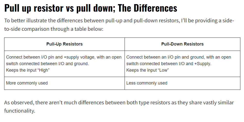
Following Prof. Gershenfeld comments about pull up vs. pull down resistors I educated myself and now can simplify my circuit by removing the pull down resistors and use the built in pull up resistors with some code changes you can see here
I used the SEEED and Fab libraries. I am still not sure what connectors to use for the button and motor/pump and so I just used the connectors in the Fab library.
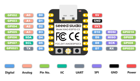
I pulled up the ESP32ESP pinout map
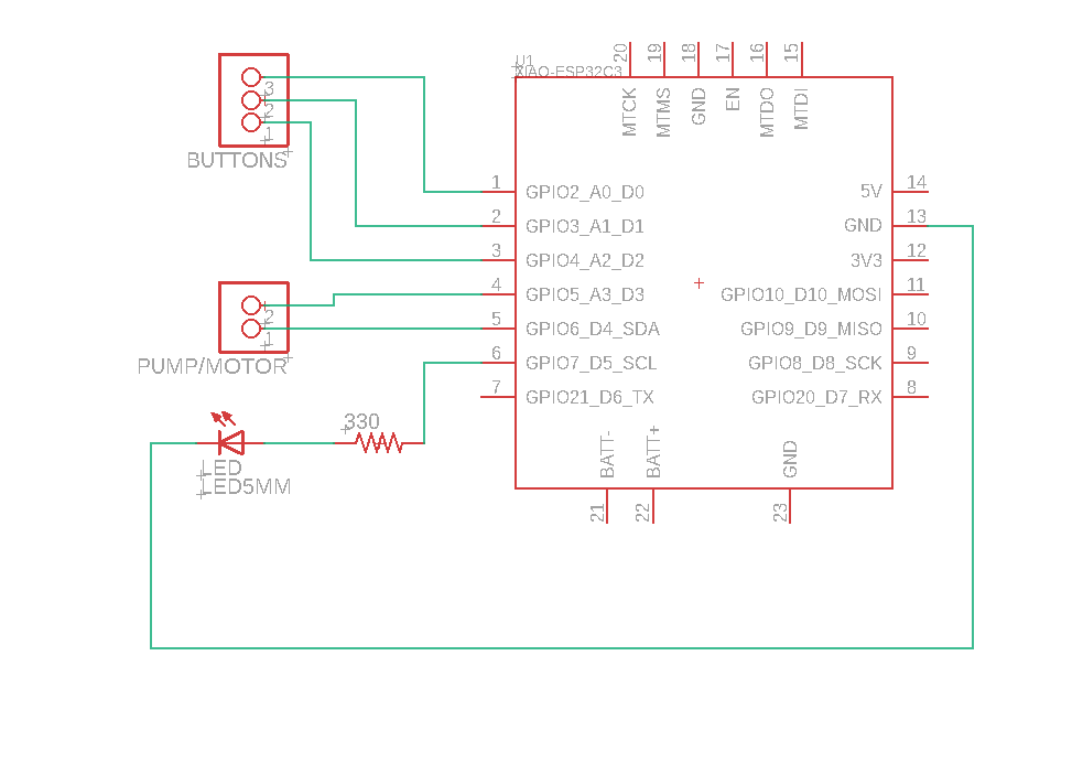
then got to updating the schematic
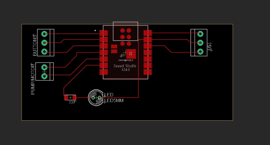
I moved to placing down the components
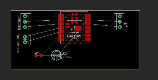
And next was routing
I finaly decided to shrink the foot print down a bit
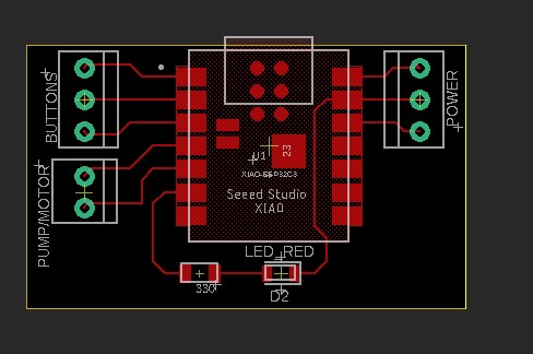
And now we can move to making the board
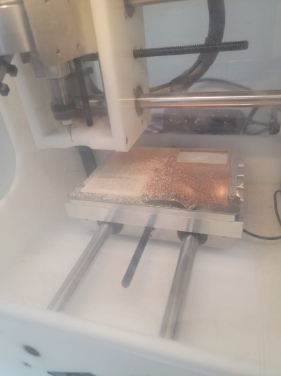
Bantam milling
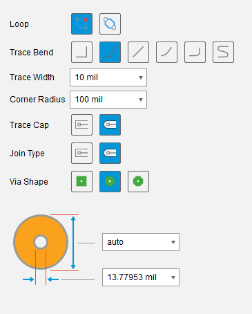
I use a 10mil trace width in the design.
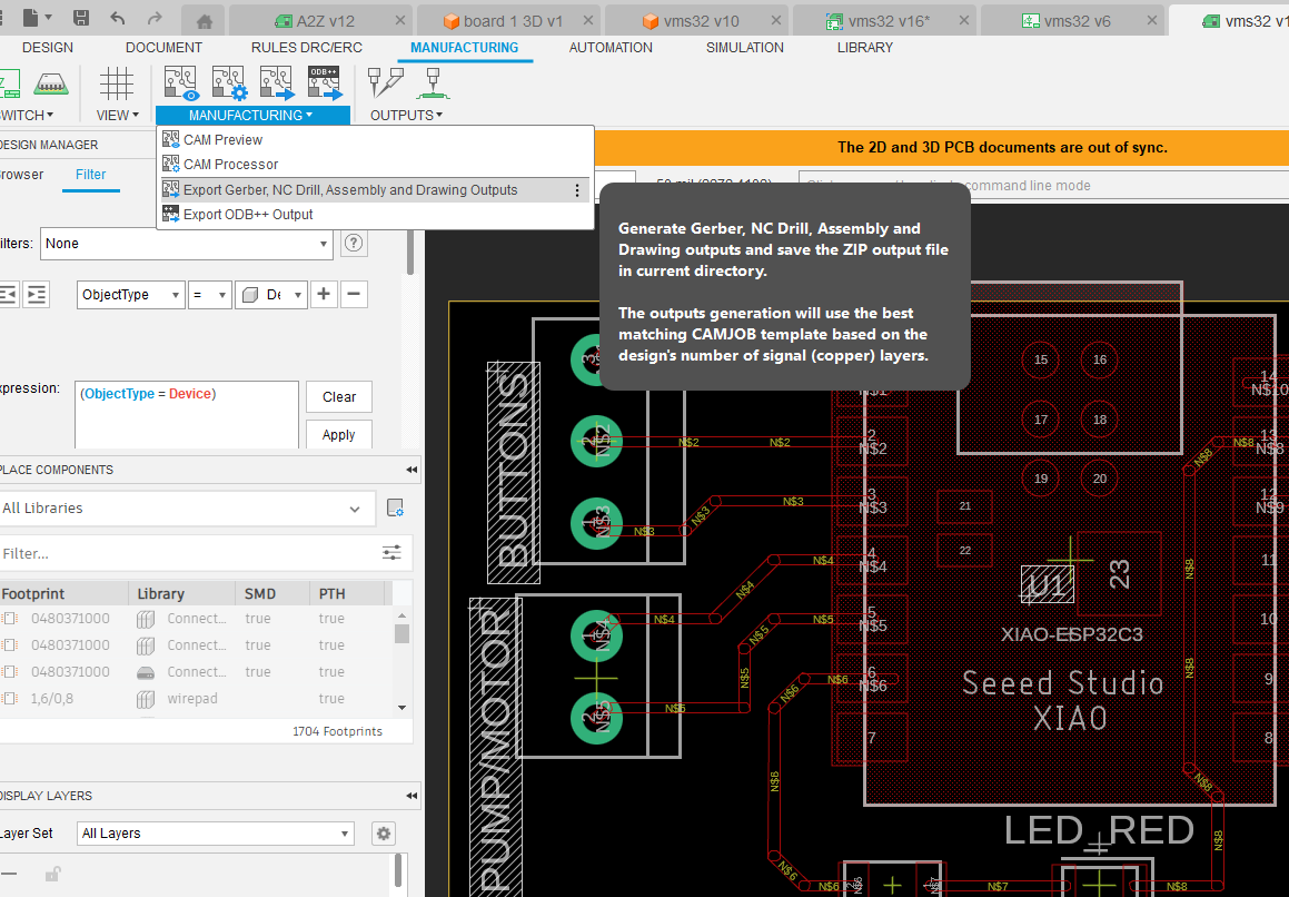
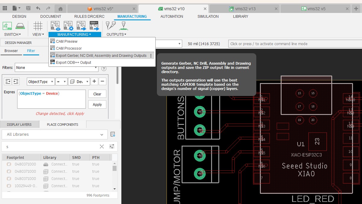
I then went to the manufacturing menu and selected "export Gerber..."
I then coped the copper_top and profile grbl files over the to Bantam milling machine.

I used the Bantam mill and it was very straight forward. I exported the file from Fusion using the postprocessing It switch between 1/32 and 1/64 inch endmill bits. The switch timing was dictated by the Bantam milling machine.
First in Fusion, I went to the manufacturing menue and experoted the files
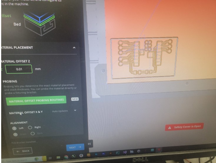
In Bantam I loaded the copper top and profile files
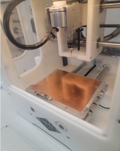
I used double sided tape and put the board in place
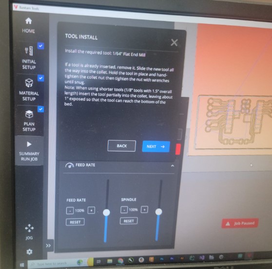
The machine made sure I loaded the right tips:
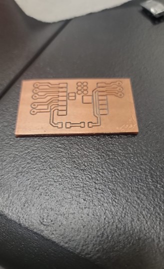
It ran through the cut
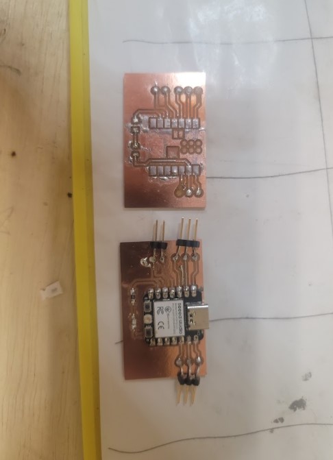
I cut 2 to make sure I had a back up without needed to set everything up again
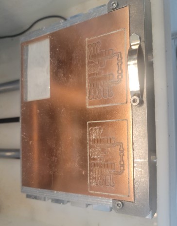
I cleaned the board with soap and water
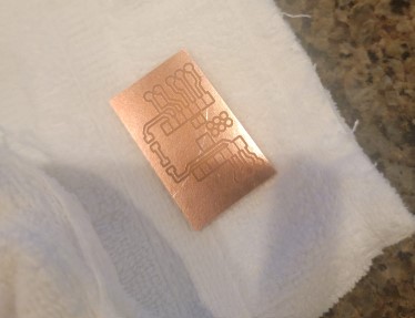
Assembly
I only had 3 components to solder the ESP32C3, a resistor and LED as well as connectors for the buttons
We did a good amount of Surface Mount Soldering during our Fab Academy prep so the getting the 3 components down was pretty straight forward
Not I the components in place (stuffing)
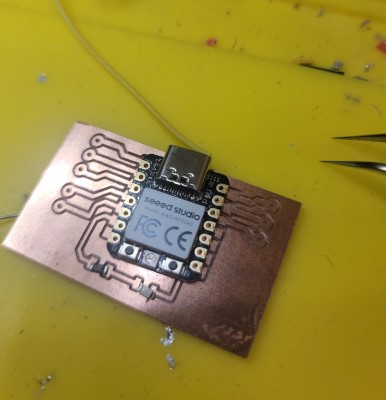
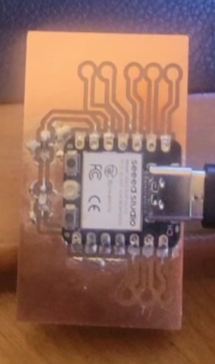
and soldered
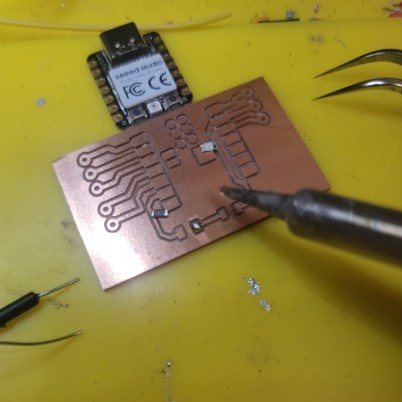
And here we have it
Coding
Here I wanted to try out Chat GPT 4.0 and so I asked him for simple blink code and he suggested
// Pin number for the LED (use the GPIO number, not the board's pin number)
const int ledPin = 7;

// Time interval for the LED to be on and off (in milliseconds)
const unsigned long interval = 1000;
unsigned long previousMillis = 0;

void setup() {
  // Set the LED pin as an output
  pinMode(ledPin, OUTPUT);
}

void loop() {
  // Get the current time
  unsigned long currentMillis = millis();

  // Check if the interval has passed
  if (currentMillis - previousMillis >= interval) {
    // Save the last time the LED state was toggled
    previousMillis = currentMillis;

    // Toggle the LED state
    digitalWrite(ledPin, !digitalRead(ledPin));
  }
}
I loaded it and we had a blinking light and we have blinking
Next I asked Chat GPT to add a button that when pressed would trigger the LED to blink 5 times
Here is the suggested code
const int ledPin = 7;
const int buttonPin = 2; // Change this to the GPIO number where the button is connected
const unsigned long interval = 1000;
unsigned long previousMillis = 0;
int flashCount = 0;
bool buttonPressed = false;

void setup() {
  pinMode(ledPin, OUTPUT);
  pinMode(buttonPin, INPUT_PULLUP); // Enable the internal pull-up resistor for the button
}

void loop() {
  unsigned long currentMillis = millis();

  if (digitalRead(buttonPin) == LOW) { // Check if the button is pressed
    buttonPressed = true;
  }

  if (buttonPressed && flashCount < 5) {
    if (currentMillis - previousMillis >= interval) {
      previousMillis = currentMillis;
      digitalWrite(ledPin, !digitalRead(ledPin));

      // Turn off the LED after it has been flashed an odd number of times
      if (digitalRead(ledPin) == LOW) {
        flashCount++;
      }
    }
  } else if (flashCount >= 5) {
    flashCount = 0;
    buttonPressed = false;
  }
}
However.....while I was getting the Button set up I pushed too hard on the connector and stripped the trace.
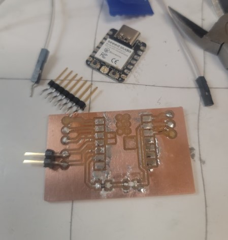
Luckily I had an extra board milled and use the heat gun to remove the components from the old board and soldered them to the new board. I got the button wired in (being more careful) and.....
We have success!!!
Milling in Fusion / Genmitsu 3020-Pro-Max
While I believe this is what we needed to get done for this week I also wanted to try and mill the board by setting up the tool path in fusion and running a small CNC mill I have at home the Genmitsu 3020-Pro-Max
Board milling set up in Fusion
I spend time watching a number of tutorials here and here
Set up was largely the same but they took different approach to the tool path choices.
Here is what I tried
First I exported the board to 3D board but made sure to uncheck the soldermask option as that will make selecting the copper traces for milling easier
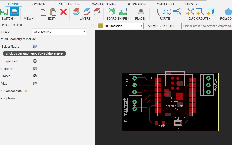
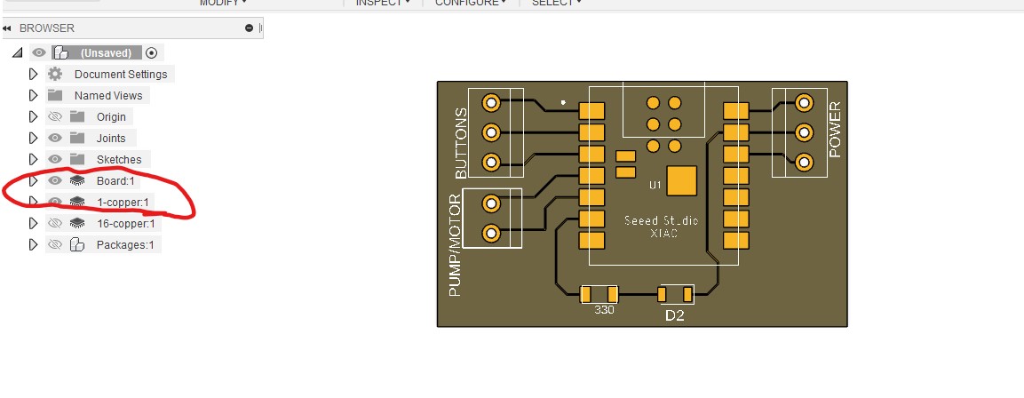
I kept the board the 1-copper layers visible which is what I want to mill
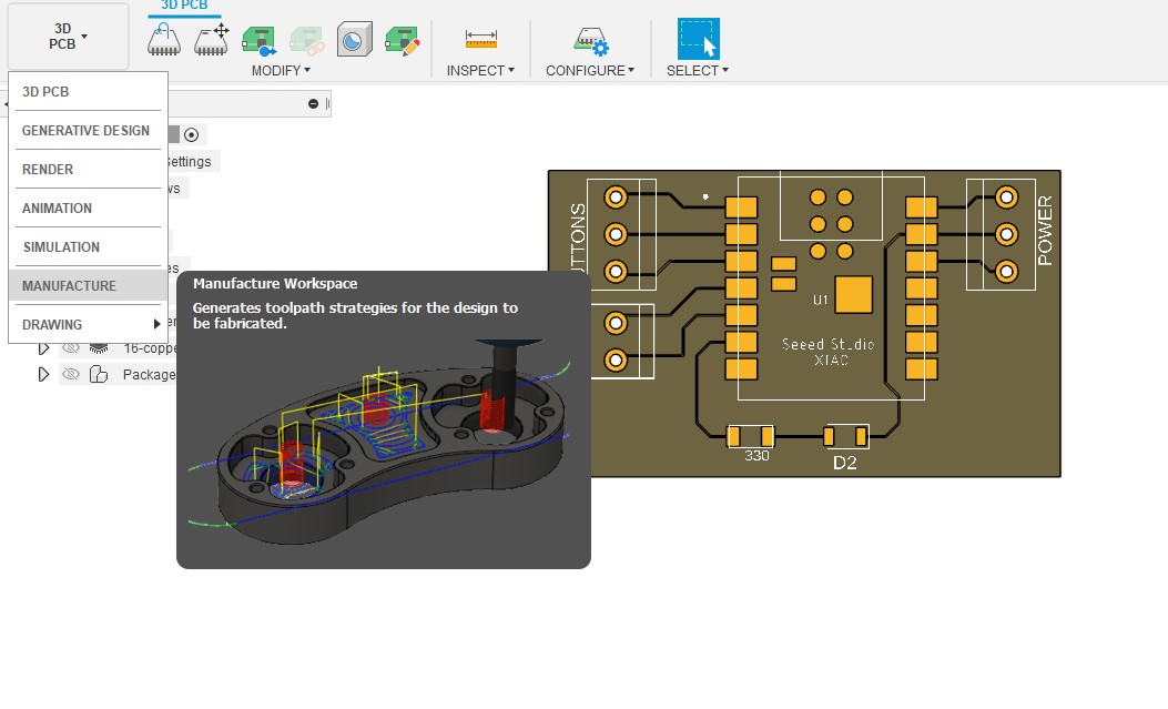
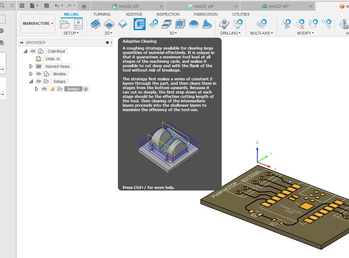
Next I moved the manufacturing workspace
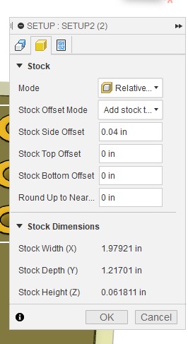
I started a new set up and selected the board as the model
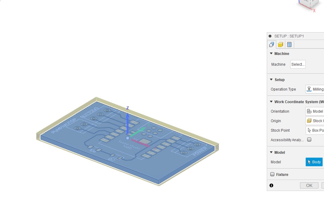
I change the top off set to 0
Tool path set up
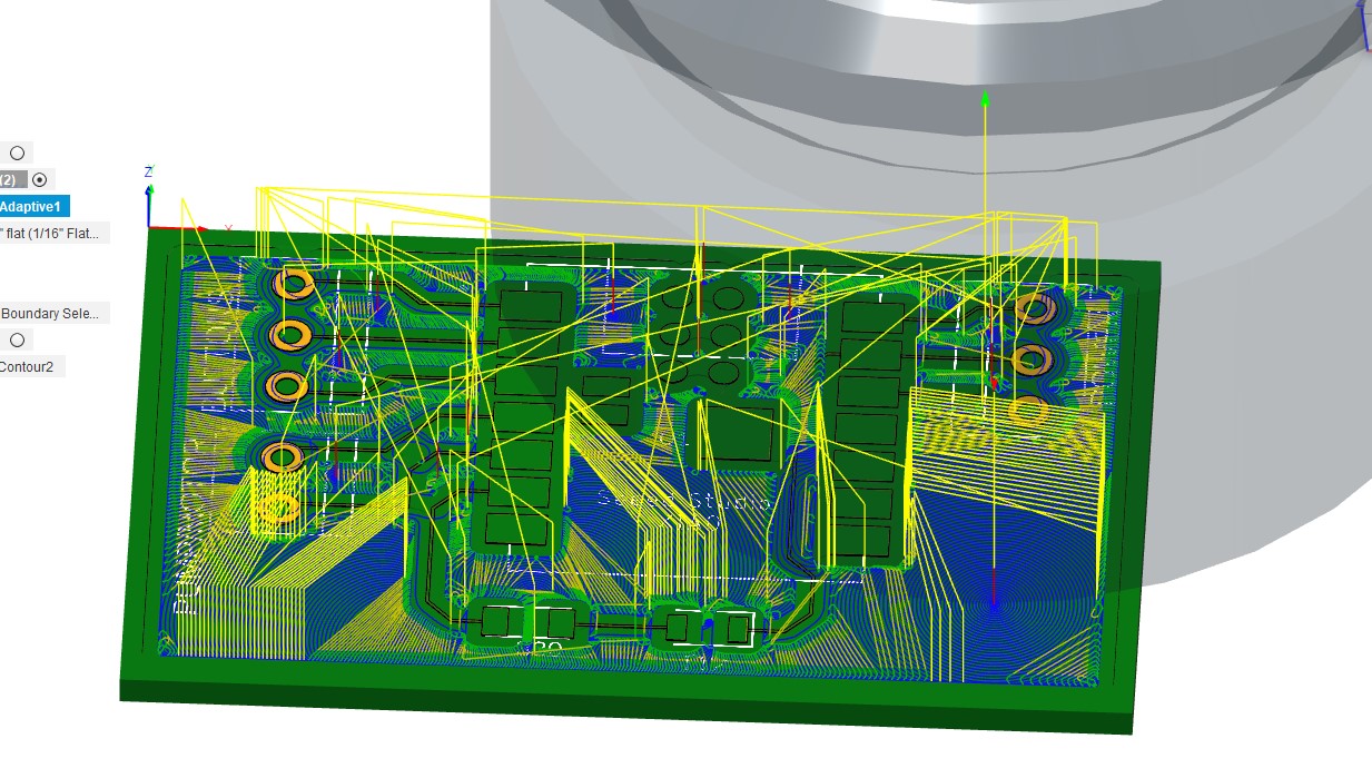
I started by the 3D adaptive clearing tool path
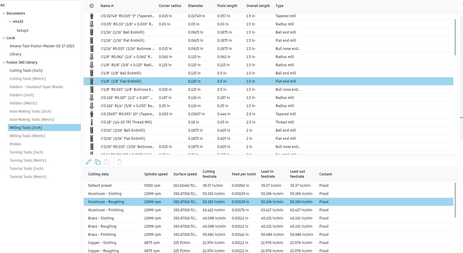
I choose a 1/8 end mill with aluminum roughing which is what they used in the tutorial (this will turn out to be a mistake for my board)
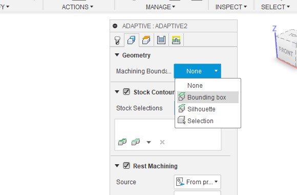
Next I set the bounding box to the shape of the board and change Tool containment to "tool inside"
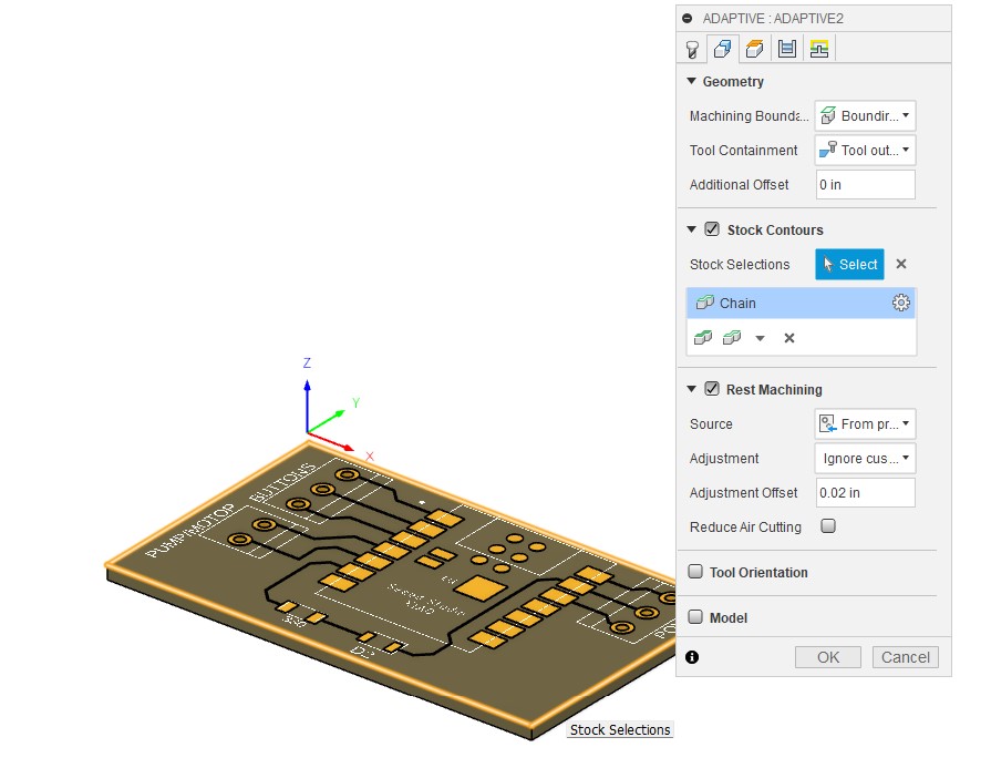
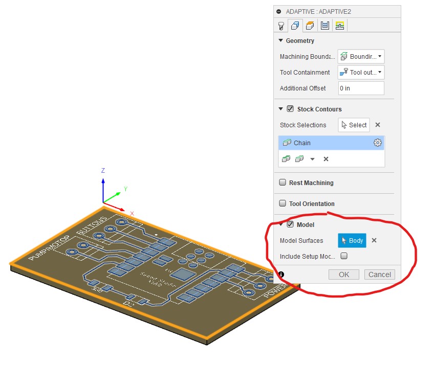
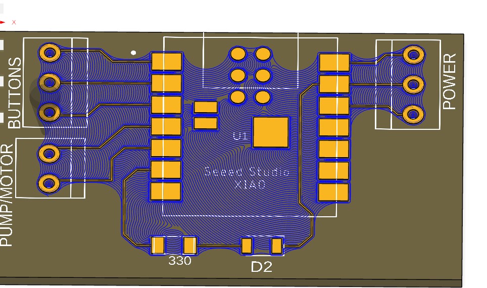
Then in the Model section I choose the copper traces
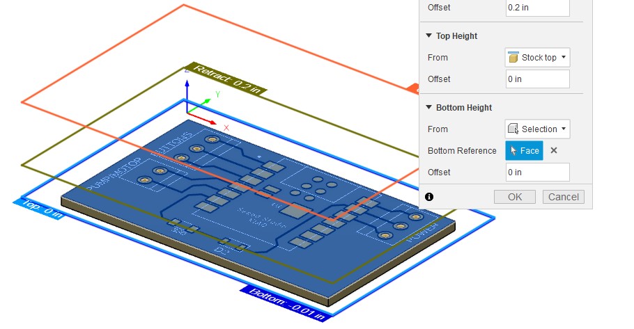
Next I selected the board surface as the Bottom height
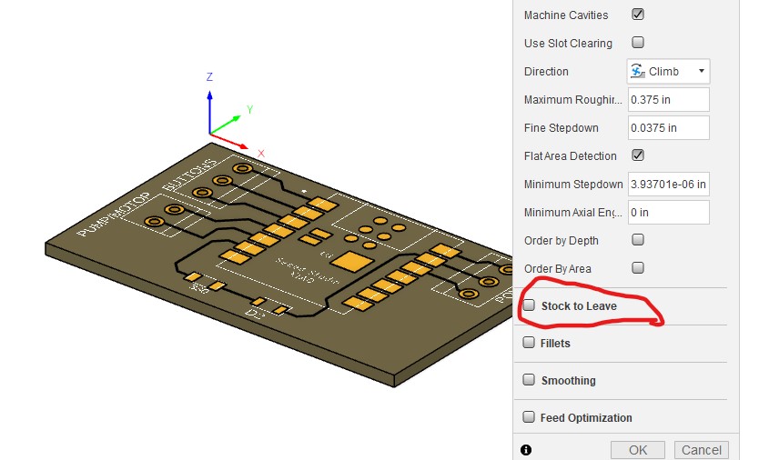
Unchecked the "stock to leave" option
what we can see here is that the tool was not cutting detailed enough.
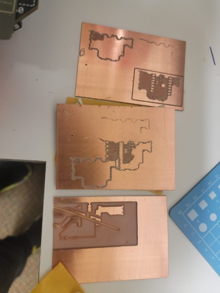
I also tried to run the machine and as you can see it did not go well
So I went and reviewed the tutorial and some more google searches and decided to make some changes. I then reviewed my set up with one of our instructors and got some more feedback and made the following changes :
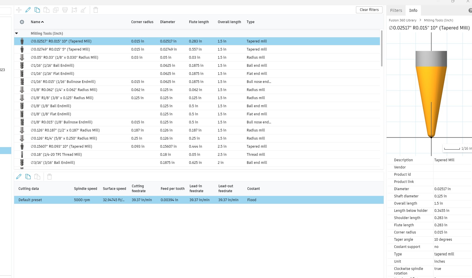
I changed the tool to a smaller one
and change the ramp type to plunge
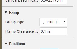
It looks much better
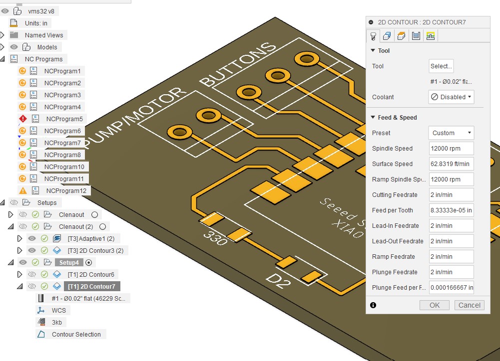
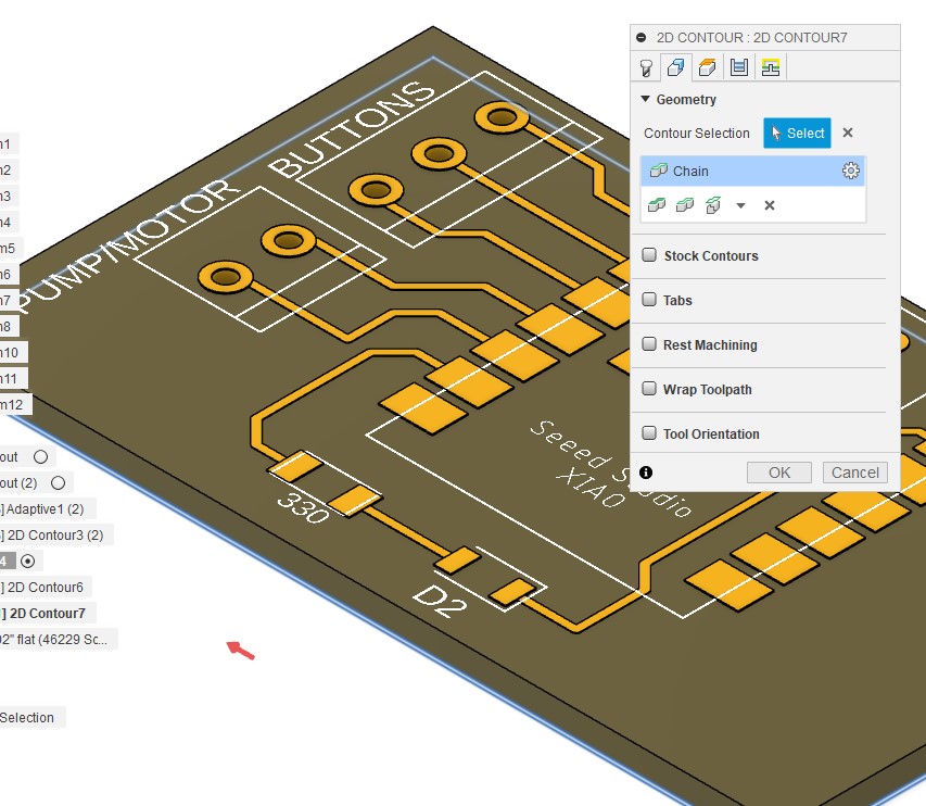
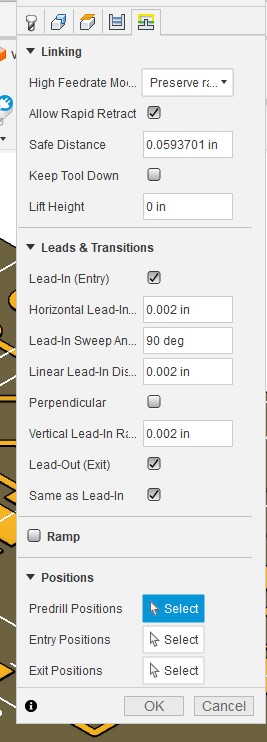
Now to add the cut around the board using the 2D countor with the following settings:
I slowed down the feed rate
Selected the bottom circumference to ensure it get all the way down
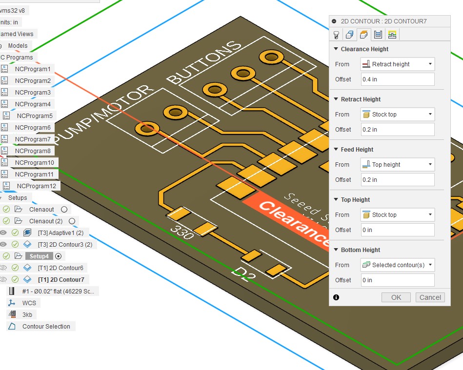
Made sure we have enough clerence on top
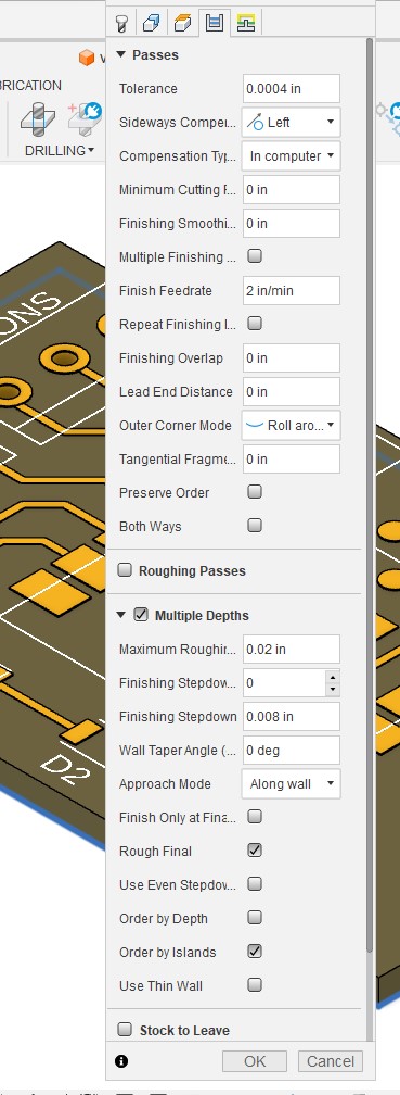
Slowed down the finish feedrate and added multiple cut depth with a 0.002 max depth
And I was good to go.
I used the same post process to get the cut file
Lef click on the set up and select post process
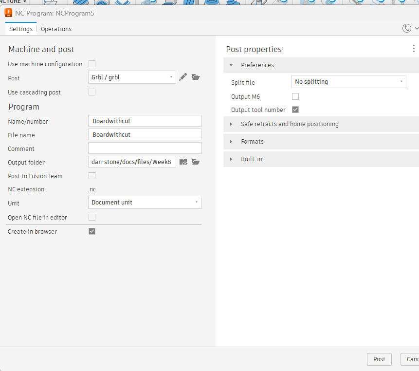
I used the GRBL output for the Genmitsu and got the needed .nc file type.

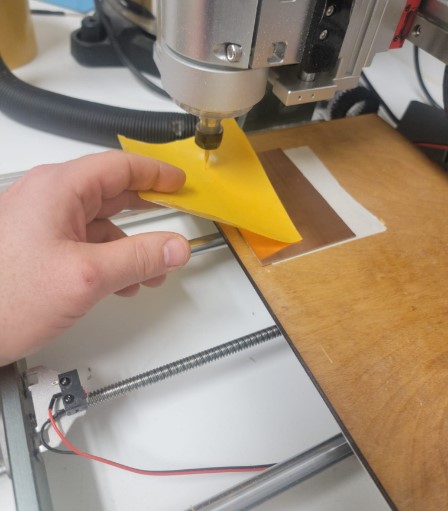
I loaded into the candle software for the cut. Put in the 0.5mm endmill bit and made sure the Zero out the Z using a paper. Making sure is hard to get out
Here is how it went
Success!!!
Reflections about using Bantam vs. Genmitsu milling machines.
The output for both milling machines were similar, the Genmitsu only used one bit and was slower while the Bantam automatically switch bit and took about half of the time.
Given the much lower cost of the Genmitsu it is a good solution for my home use given the lower volume of work compared to the lab.
File for this week here
Thank you to Adrian Torres, you can find the design files and png for the fab xiao on his site here