14. Networking and communications
This was a tough week. I was optimistic at the bringing as I got I2C to work between 2 Arduino quickly but ended up spending a lot of time trying to get I2C wired communication going on the xiao with no success.
As we were running out of time I pivoted and focused on URTI communication between the Xiao board I designed and the Fax Xiao board. I coded a simple chat set up which worked well. As I do not use Micropython very much it was a good stretch.
We then used the Xiao board to communication with my group mate's 1614 based board using I2C here. This gave me hope that maybe moving to Micropython maybe be the key to getting the I2C effort to work.
Goals Individual assignment: design, build, and connect wired or wireless node(s) with network or bus addresses
Accomplishment
-
Set up URTI communication between two differnt Xiao RP2040 based boards
-
Got I2C to work with 2 Arduinos
-
Learned how to scan for I2C devices
-
Partial success in sending I2C messages between 2 xiao RP2040 using micropython
URTI communication with 2 Xiao RP2040
I followed the tutorial that our local instructor recommended
I typicaly work in Arduino/C code but had to move to micro python on this one
Thank you stuart-christhilf who followed the same tutorial and was very clear in the code set up which was a bit confusing for someone who does not use python easly.
Here is the network I will be making
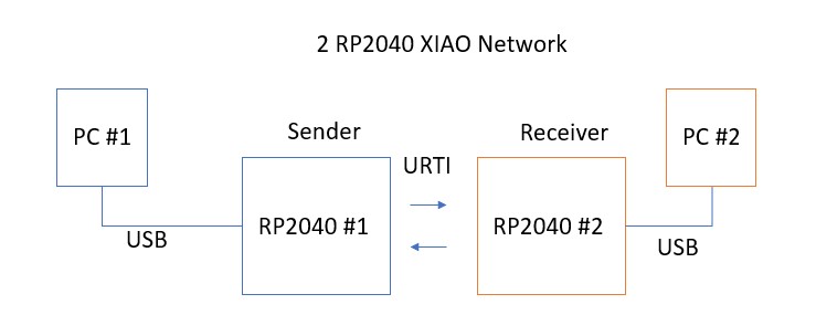
I save the library to both RP2040 Xiao - one on the board I designed and one on a breadboard
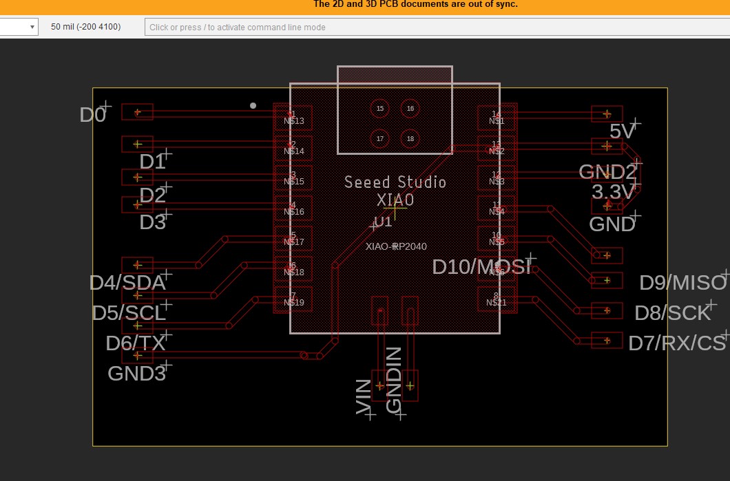
I connected thier RX and Tx to each other based on the RP2040 pinout as well as the GND.
GND-->GND PIN 8 --> Pin 9 Pin 9 --> Pin 8
I saved the following file on both so we have the required library on both name easy_comms.py
#Easy comms is a simple class that allows you to send and receive messages over a serial port.

from machine import UART, Pin
from time import time_ns

class Easy_comms:

    uart_id = 0
    baud_rate = 9600
    timeout = 1000 # milliseconds

    def __init__(self, uart_id:int, baud_rate:int=None):
        self.uart_id = uart_id
        if baud_rate: self.baud_rate = baud_rate

        # set the baud rate
        self.uart = UART(self.uart_id,self.baud_rate)

        # Initialise the UART serial port
        self.uart.init()

    def send(self, message:str):
        print(f'sending message: {message}')
        message = message + '\n'
        self.uart.write(bytes(message,'utf-8'))

    def start(self):
        message = "ahoy\n"
        print(message)
        self.send(message)

    def read(self)->str:
        start_time = time_ns()
        current_time = start_time
        new_line = False
        message = ""
        while (not new_line) or (current_time <= (start_time + self.timeout)):
            if (self.uart.any() > 0):
                message = message + self.uart.read().decode('utf-8')
                if '\n' in message:
                    new_line = True
                    message = message.strip('\n')
                    # print(f'received message: {message}')
                    return message
        else:
            return None
I then loaded Thonny on anothre computer and ran one piece of code for the receiver and one for the sender
Receiver code:
# Pico_comms_a
# Sends commands and listens to responses from pico_comms_b

from easy_comms import Easy_comms
from time import sleep

com1 = Easy_comms(uart_id=0, baud_rate=9600)
com1.start()

while True:
    message = ""
    message = com1.read()

    if message is not None:
        print(f"message received: {message.strip('\n')}")
    sleep(1)
Sender code:
# Pico_comms_b
# Sends commands and listens to responses from pico_comms_a

from easy_comms import Easy_comms
from time import sleep

com1 = Easy_comms(uart_id=0, baud_rate=9600)
com1.start()

count = 0
while True:
    # send a message
    com1.send(f'hello, {count}')

    #check for messages
    message = com1.read()

    if message is not None:
        print(f"message received: {message.strip('\n')}")
    sleep(1)
    count +=1
and then ran them.... initial this did not work but that is because I did not have the GND connected. Once I got the GND connected it was all good as per the video:
Simple chat on RP2040s
I wanted to change it up and replace the set message with something the user types into the shell.
As my Python code is very rudimentary I decided to ask ChatGPT for help. I asked ChatGPT to replace the set message with input that is typed into the shell by the user.
I got the code change and make the following adjustments: 1. Remove the count 2. Changed the order so a message is reieceved and then user is asked for a response
from easy_comms import Easy_comms
from time import sleep

com1 = Easy_comms(uart_id=0, baud_rate=9600)
com1.start()

count = 0
while True:
    # check for messages
    received_message = com1.read()

    if received_message is not None:
        print(f"Received message: {received_message.strip('\n')}")

    # prompt user for message
    message = input("Enter a message: ")

    # send the message
    com1.send(f'{message}')

    sleep(1)
    count += 1
i
and
from easy_comms import Easy_comms
from time import sleep

com1 = Easy_comms(uart_id=0, baud_rate=9600)
com1.start()

count = 0
while True:
    # check for messages
    received_message = com1.read()

    if received_message is not None:
        print(f"Received message: {received_message.strip('\n')}")

    # prompt user for message
    user_input = input("Enter a message: ")

    # send the message
    com1.send(f'{user_input}')

    sleep(1)
    count += 1
and here you can see it in action:
And we have wired networking working!!!
I2C 2 RP2040
I have 2 RP2040 boards that I have been using one is the Fab Xiao and one is the board I designed for my final project. (big thank you to Adrian Torres)
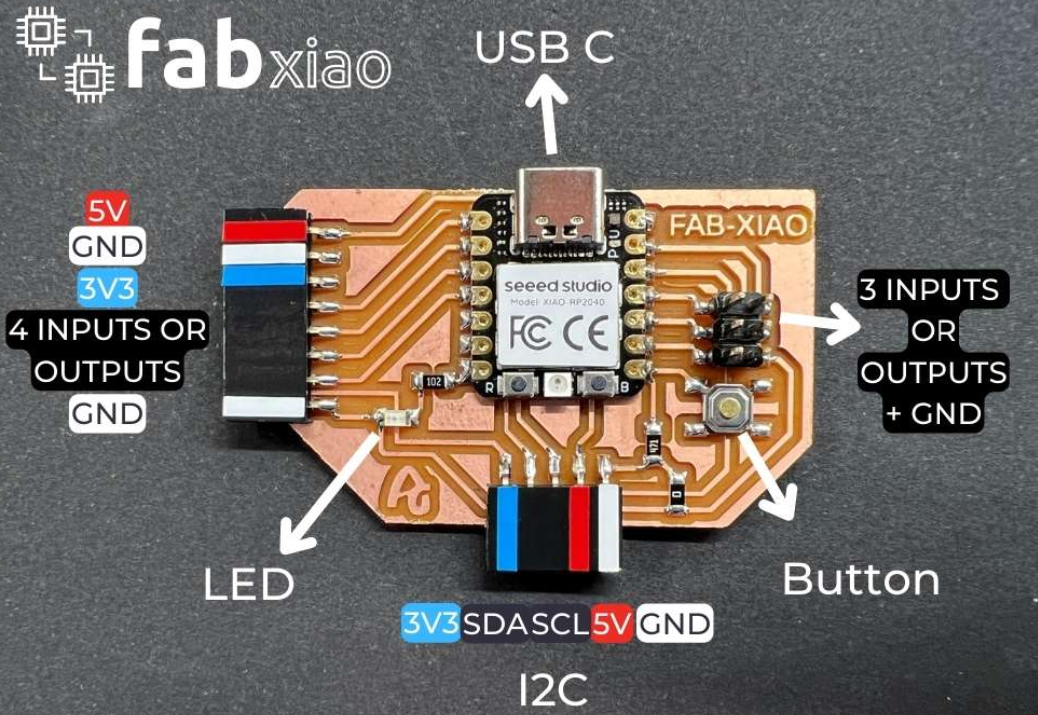
You can find more about the Fabxiao here
I started off by planning to connect them via I2C and get have one of the board connected to the PC typing in a number from the keyboard. That number would be sent from the Server/Main RP2040 the client RP2040 that would flash the onboard LED that number of times and print that number on the serial number as well.
I asked GPT for code to achieve the above and after some tweaking to the answer here is the code I started with for the server RP2040
#include <Wire.h>

#define KEY_PIN 1

void setup() {
  pinMode(KEY_PIN, INPUT_PULLUP);
  Wire.begin(); // Start I2C communication
  Serial.begin(9600); // Start serial communication


}

void loop() {

      if (digitalRead(KEY_PIN) == LOW) {
    int num = readSerialInput(); // Read input from the Serial Monitor
    Wire.beginTransmission(0x40); // Set I2C address to 0x40
    Wire.write(num);
    Wire.endTransmission();
    Serial.print("Sent number: ");
    Serial.println(num);
  }
}

int readSerialInput() {
  while (!Serial.available()) {}
  int num = Serial.parseInt();
  return num;
     Serial.write("input");
        Serial.write(num);
}
and for the receiver
#include <Wire.h>

#define LED_BUILTIN

void setup() {
  pinMode(LED_BUILTIN, OUTPUT);

  Wire.begin(0x40); // Set I2C address to 0x40
  Wire.onReceive(receiveEvent);
  Serial.begin(9600); // Start serial communication
}

void loop() {}

void receiveEvent(int numBytes) {
  int num = 0;
  while (Wire.available()) {
    num = Wire.read();
  }
  flashLED(num);

  // Print the received number to the Serial Monitor
  Serial.print("Received number: ");
  Serial.println(num);
}

void flashLED(int num) {
  for (int i = 0; i < num; i++) {
    digitalWrite(LED_BUILTIN, HIGH);
    delay(100);
    digitalWrite(LED_BUILTIN, LOW);
    delay(100);
  }
}
I2C address each one had a different address:
Server: The command c Wire.begin(); sets the default address as 0x08
Client: The command c Wire.begin(0x40); sets the address as 0x40
I wired the SCL and SDI across both board and connected the ground as I saw that as a suggestion online.
It did not work :(
Testing I2C on each board!
I wanted to make sure sure both board had I2C working since one of the boards were working so I hooked up the BMP280 I2C temp sensor I used in input week you can see [here[https://fabacademy.org/2023/labs/charlotte/students/dan-stone/assignments/week12/#bmp280-moving-to-the-rp2040]] to both and loaded the code....they both worked create.
To make sure the boards LED also works I loaded Blink and made sure both blinked.
So Both board work and both I2C work.
Checking the connection
I wanted to see if I had both of them connected and I found the following code that scans every address and let you know if there is an I2CA device connected.
#include <Wire.h>

void setup() {
  Wire.begin();
  Serial.begin(9600);
  while (!Serial);
  Serial.println("\nI2C Scanner");
}

void loop() {
  byte error, address;
  int nDevices;

  Serial.println("Scanning...");

  nDevices = 0;
  for (address = 1; address < 127; address++) {
    Wire.beginTransmission(address);
    error = Wire.endTransmission();

    if (error == 0) {
      Serial.print("I2C device found at address 0x");
      if (address < 16) {
        Serial.print("0");
      }
      Serial.print(address, HEX);
      Serial.println("  !");

      nDevices++;
    }
    else if (error == 4) {
      Serial.print("Unknow error at address 0x");
      if (address < 16) {
        Serial.print("0");
      }
      Serial.println(address, HEX);
    }
  }
  if (nDevices == 0) {
    Serial.println("No I2C devices found\n");
  }
  else {
    Serial.println("done\n");
  }
  delay(5000);
}
I loaded this code onto server and connection seems good:

Running I2C connection on Arduino
Here is the network I will be making using Arduinos to test the code
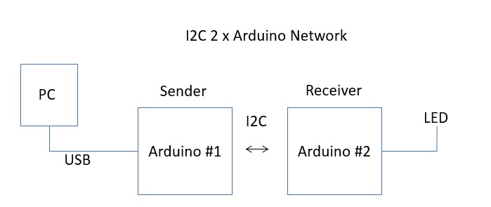
I hooked up to arduino and ran simple communication code.
Here is the code for the sender
// Wire Peripheral Sender
// by Nicholas Zambetti <http://www.zambetti.com>

// Demonstrates use of the Wire library
// Sends data as an I2C/TWI peripheral device
// Refer to the "Wire Master Reader" example for use with this

// Created 29 March 2006

// This example code is in the public domain.


#include <Wire.h>

void setup() {
  Wire.begin(8);                // join i2c bus with address #8
  Wire.onRequest(requestEvent); // register event
  Serial.begin(9600);

}

void loop() {
  delay(100);

}

// function that executes whenever data is requested by master
// this function is registered as an event, see setup()
void requestEvent() {
  Wire.write("hello "); // respond with message of 6 bytes
  // as expected by master
  Serial.println("sent");
}
and code for the receiver
// Wire Controller Reader
// by Nicholas Zambetti <http://www.zambetti.com>

// Demonstrates use of the Wire library
// Reads data from an I2C/TWI peripheral device
// Refer to the "Wire Peripheral Sender" example for use with this

// Created 29 March 2006

// This example code is in the public domain.


#include <Wire.h>

void setup() {
  Wire.begin();        // join i2c bus (address optional for master)
  Serial.begin(9600);  // start serial for output
   pinMode(LED_BUILTIN, OUTPUT);
}

void loop() {

   Serial.println("ready");
   Wire.requestFrom(8, 6);    // request 6 bytes from peripheral device #8
  while (Wire.available()) { // peripheral may send less than requested
    char c = Wire.read(); // receive a byte as character
    Serial.println(c);         // print the character
      digitalWrite(LED_BUILTIN, HIGH);  // turn the LED on (HIGH is the voltage level)
  delay(250);                      // wait for a second
  digitalWrite(LED_BUILTIN, LOW);   // turn the LED off by making the voltage LOW
  delay(250);                      // wait for a second
  }

  delay(100);
}
I hook up SCL --- SCL SDA --- SDA GND --- GND and.....it worked well!!
Coding the Xiao RP2040 for I2C in Arduino'
I tried to run the same code I ran on the arduino, the code above that I put together and no matter what I do the code compiles, loads and then .... nothing happens.
After working with the Adam Durrett from my team we got the I2C to work with Micro python across out two projects so after many many hours for trouble shooting the C code I decide to pivot and give I2C a try on the Xiaos with Micropython instead.
Coding the Xiao RP2040 for I2C in Micropython
I set up 2 simple pieces of code a sender:
import machine
import utime

led = machine.Pin(25, machine.Pin.OUT)

i2c = machine.I2C(1, scl=machine.Pin(7), sda=machine.Pin(6), freq=400000)
address = 25

while True:
    try:
        # Read 2 bytes of data from the I2C device at the specified address
        print(i2c.scan())
        print(i2c.writeto(address, b'1'))


    except OSError as e:
        x=5
# Wait for 1 second before reading data again
and a receiver
import machine
import utime

led = machine.Pin(25, machine.Pin.OUT)

i2c = machine.I2C(1, scl=machine.Pin(7), sda=machine.Pin(6), freq=400000)
address = 25

# Define a buffer to store received data
buffer_size = 1
buffer = bytearray(buffer_size)

def on_receive(data):
    print("Received message: ", data)

while True:
    try:
        # Read data from the I2C device into the buffer
        i2c.readfrom_into(address, buffer)

        # Check if any data was received
        if buffer[0] != 0:
            on_receive(buffer)

    except OSError as e:
          x=5

    # Wait for 100 milliseconds before checking for new data again
Here is the network I will be making
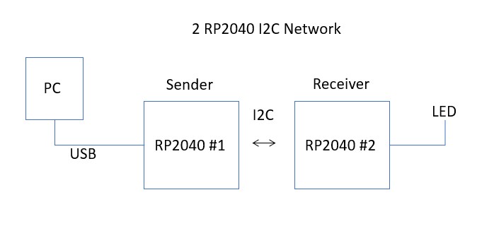
I connected the SDA and SCL and GNDs.
We got some communication going as you can see in the video but it still need some tweaking.
Unfortunately, a misstep when I adjusted the wires led to some smoke coming from one of the boards and a dead RP2040 which was the last one I had. I believe the URTI completed the requirement for the week and so I will stop here on the I2C as I am out of time and will need to get a new RP2040/board etc. and will refocus on final project and next week assignment
Here are the files for the week