7. Electronics design
Goals
In this week group work our goal was to use the test equipment in your lab to observe the operation of a micro controller circuit board.
Our group used an oscilloscope and spectrum analyzer to measure elements of the RP2040 based board we build Fab Xiao made buy ADRIÁN TORRES here as well the RP2040 based Morse Code generator I created in embedded programming week
You can see our results here
Clearly knowing how to use the right testing equipment is critical in trouble shooting boards.
Individual:
Design a development board to interact and communicate with an embedded microcontroller
Extra credit: try another design workflow
Extra credit: make a case for it
Extra credit: simulate its operation
Accomplishments
-
Learned basic use of eagle via a set of tutorials
-
Designed my first board based on a design I made during embedded programming week
-
Designed my second board that can potentially be the main board for my final project
Learning Eagle and board #1
I have never design a board and so I was very excited to get going on this one. I decided to try out Eagle as that is the focus on most of my classmates this week.
I went through the 5 part tutorial as a starting point here
I then decided to try an replicate the Vegetable Washing Machine control board I programed in embedded programming week you can see Here
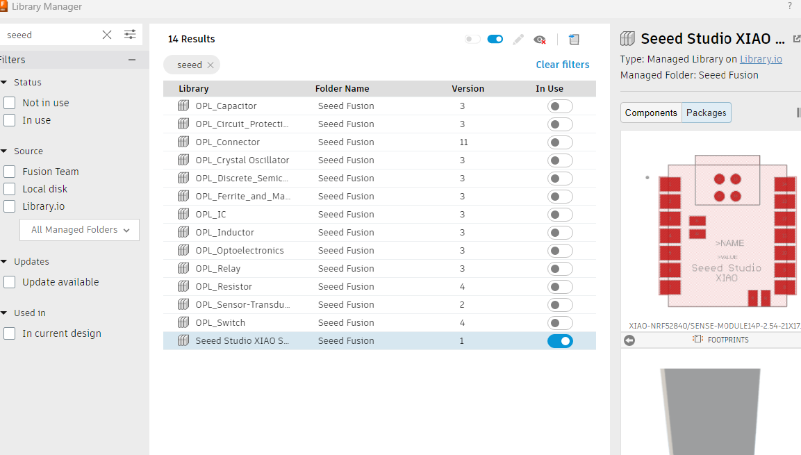
I started off by set up my Eagle work space and enabling some libraries, in particular finding the one for SEEED RP2040
I then pulled the parts into place
Next was adding all the rest of the parts and made the base set of connections
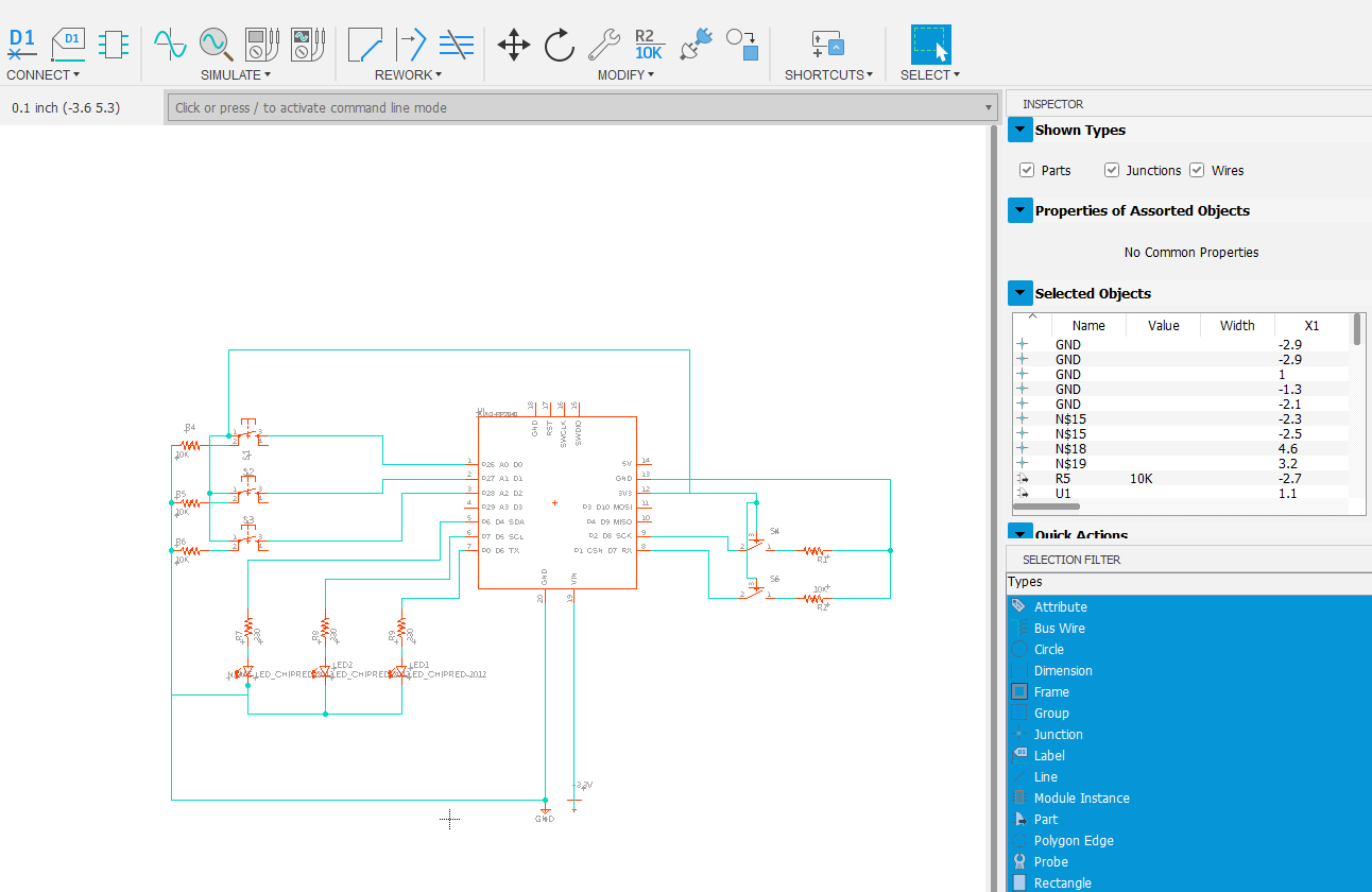
I wanted to get the board all clean and so added the values of each resistor
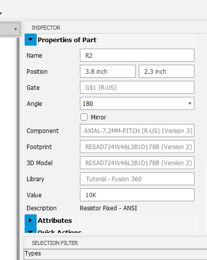
I used the inspector window on the side to quickly access info to speed things up
I then grouped and labeled parts - please note that I used LEDs to stand in for a motor and pump and will replace with connectors in the next rev
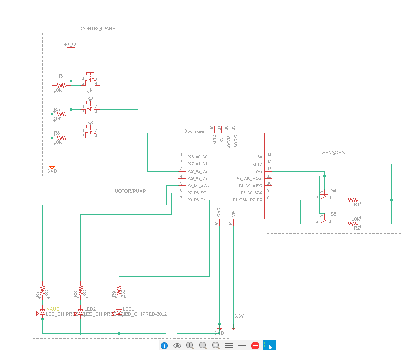
and finally put a frame around it and we are good to put to the parts placement
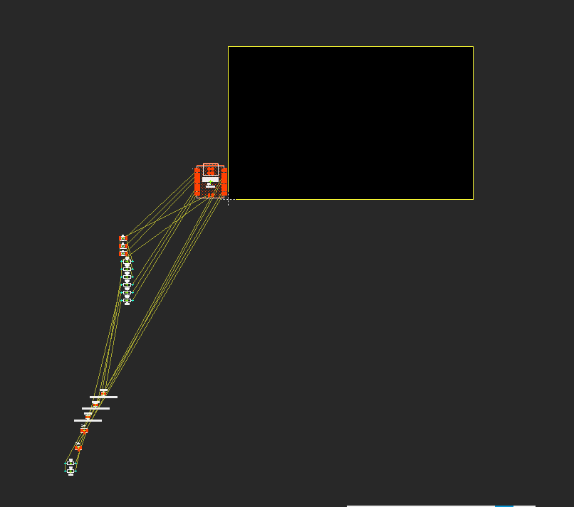
I then started to move the parts into the general areas I had in mind for them
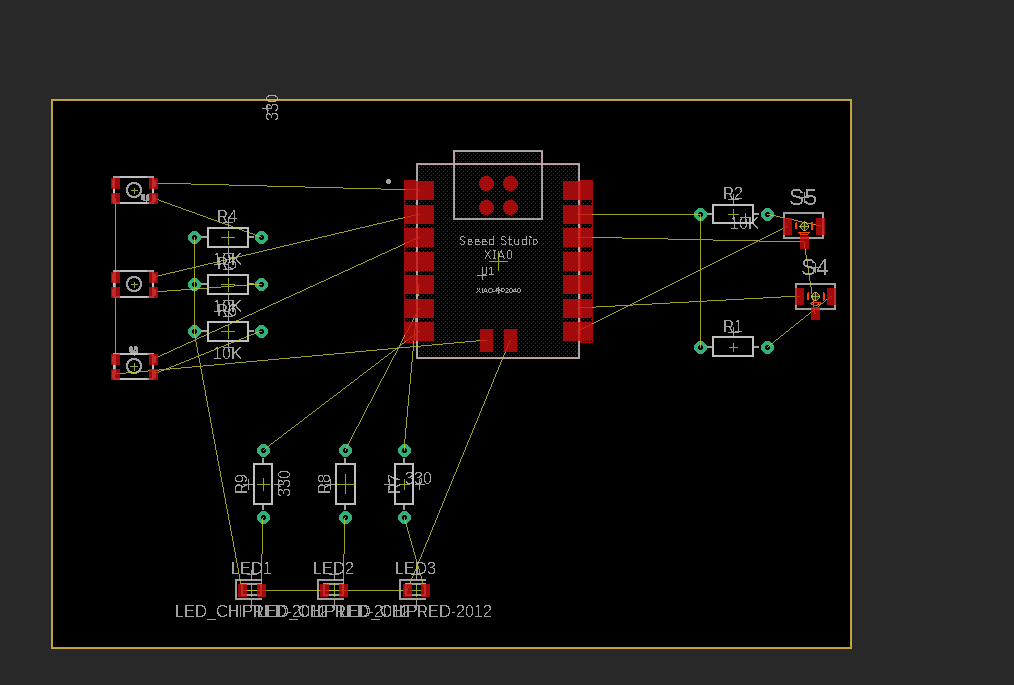
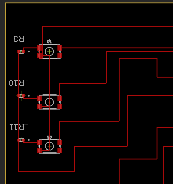
I started putting down the routes but ran into the puzzle in the top right with a landlocked connection.
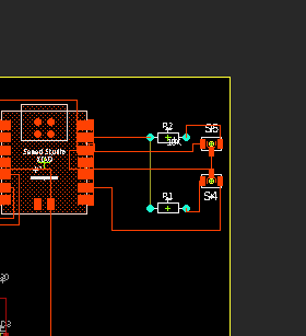
I used the resistor as a bridge
I however figured out at this point that I was using the wrong resistors and needed the surface mound components rather then the drill through and so I had to go back and start replacing the resistor in my schematic
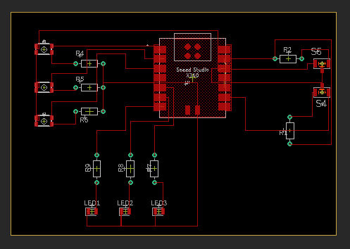
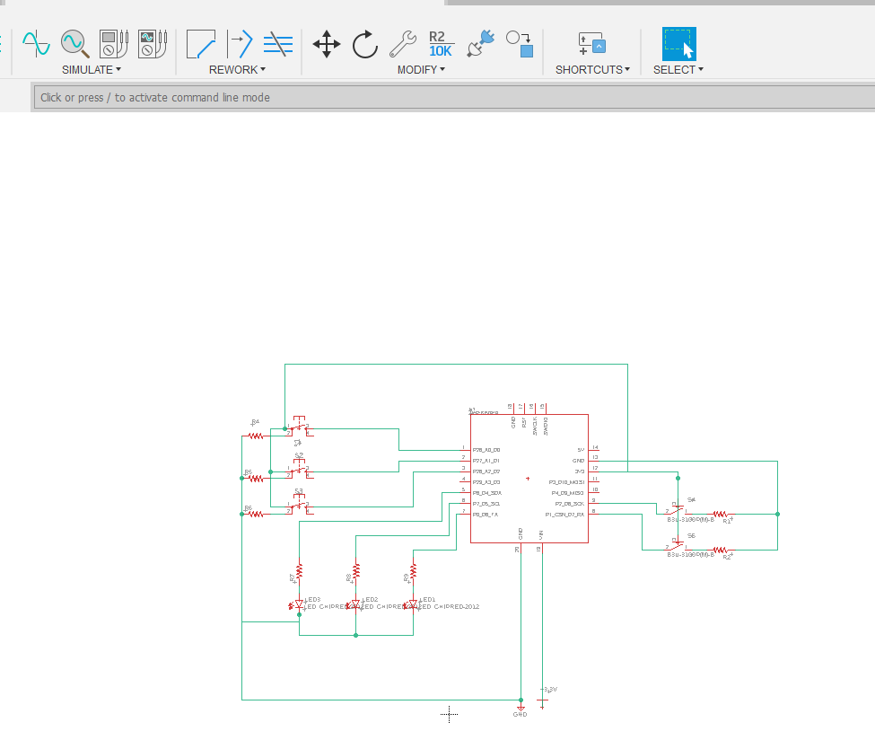
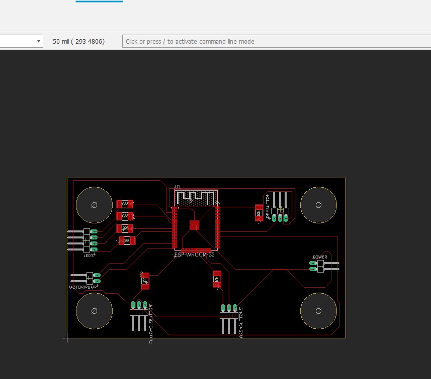
I had to redo the placement and routing with the new components
That seem to work well and so I did the same for all of them
I still had the land locked resistor and now the SMD component I choose was too small to be a bridge and so I used one of the larger resistors as a bridge
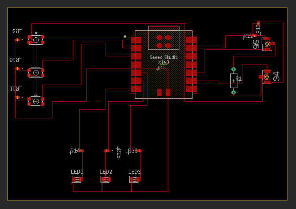
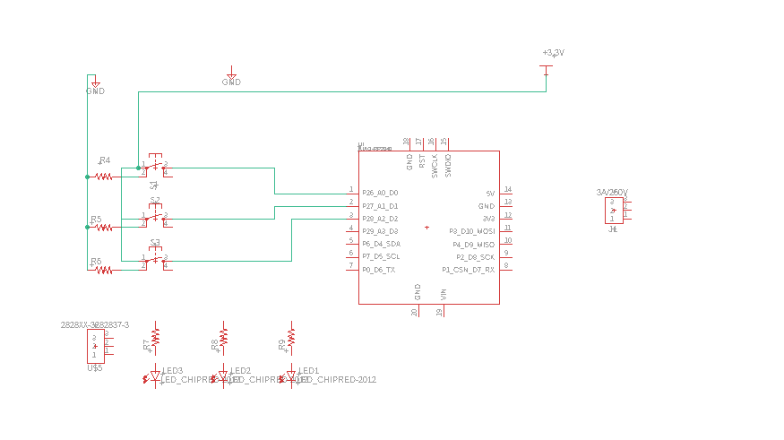
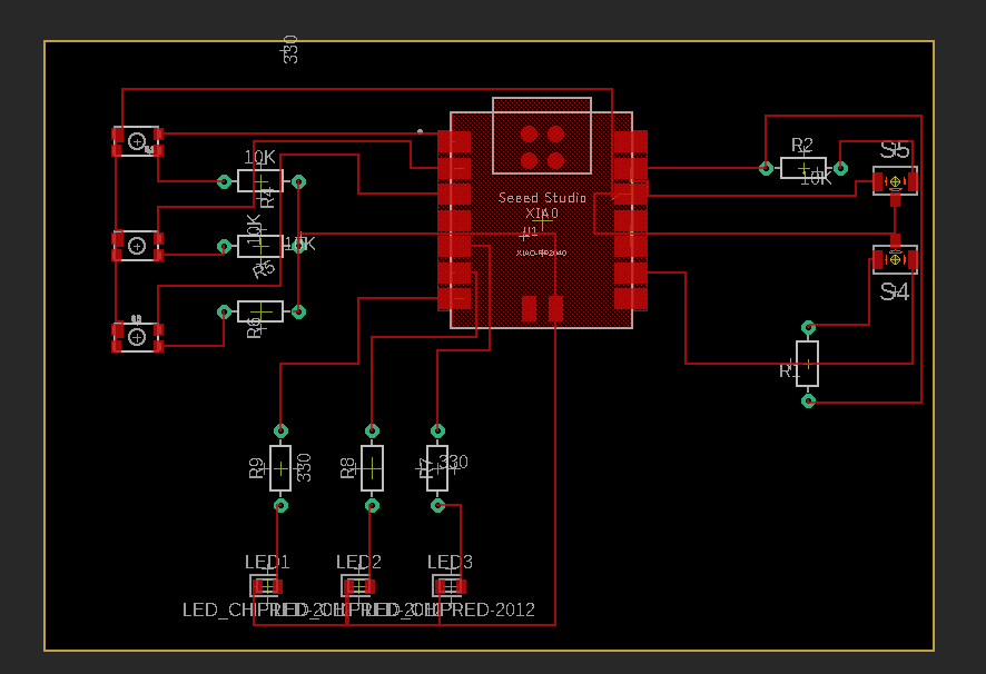
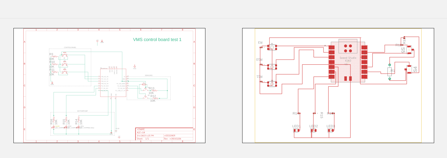
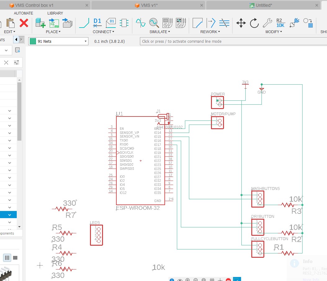
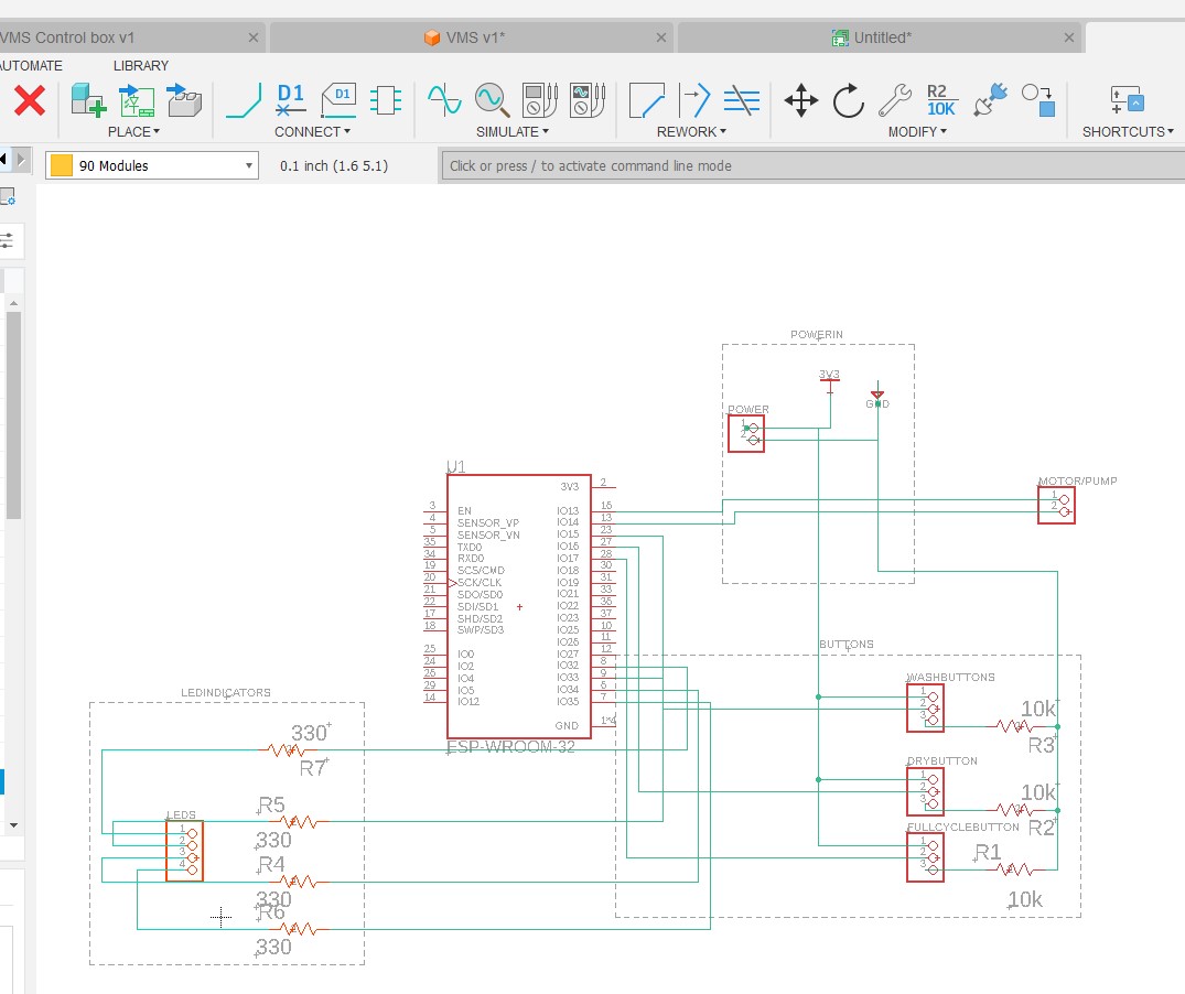
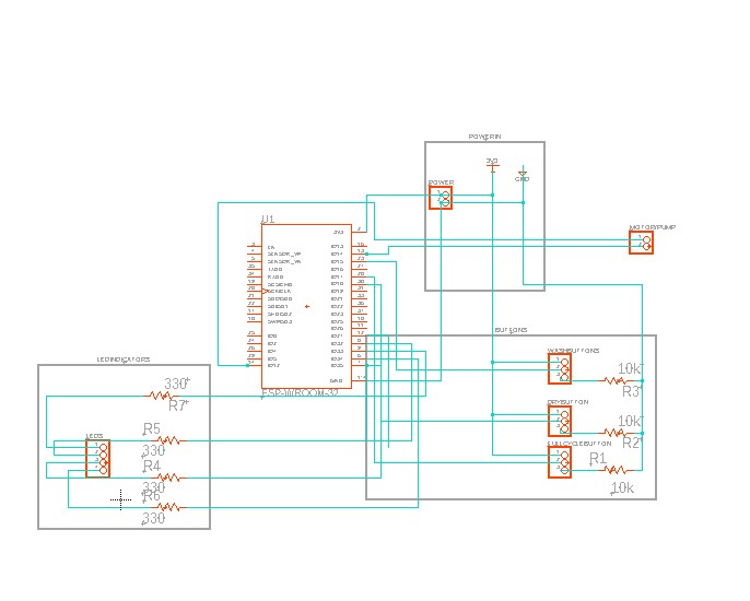
And here is the overview of the schematic
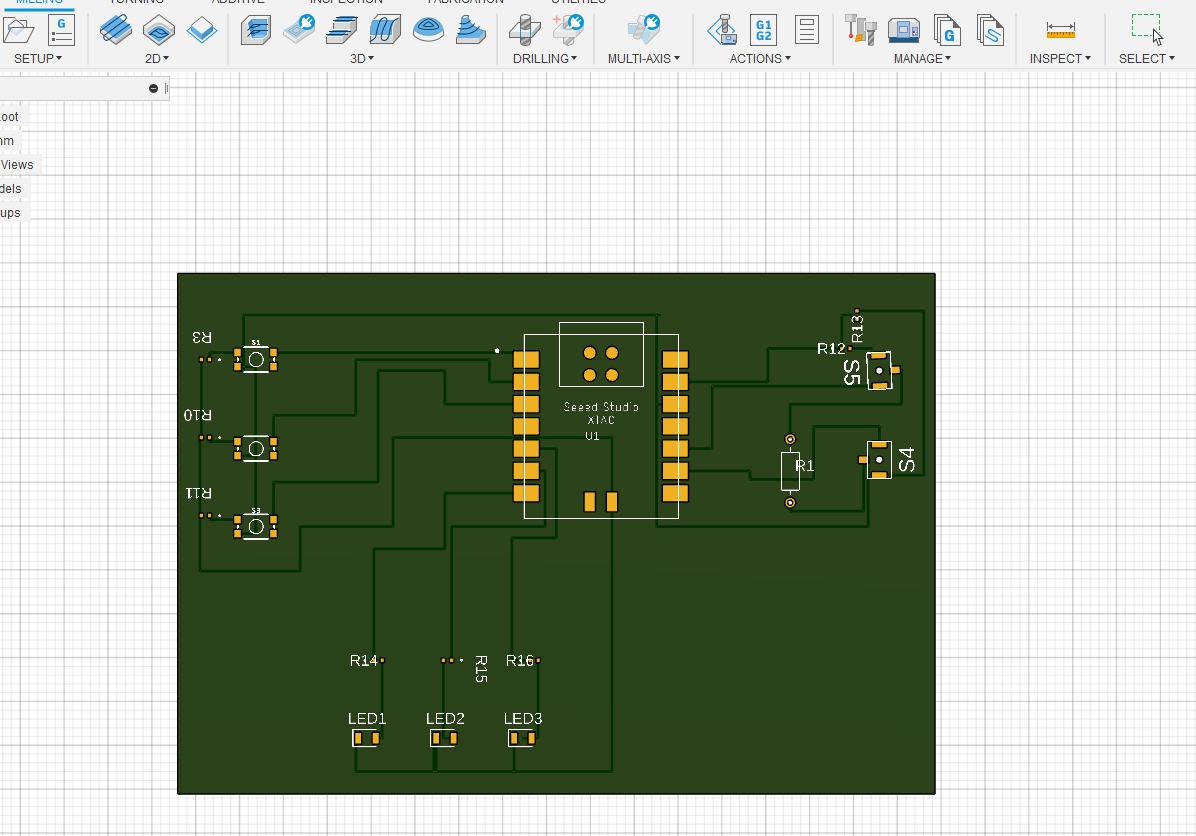
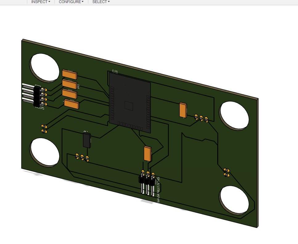
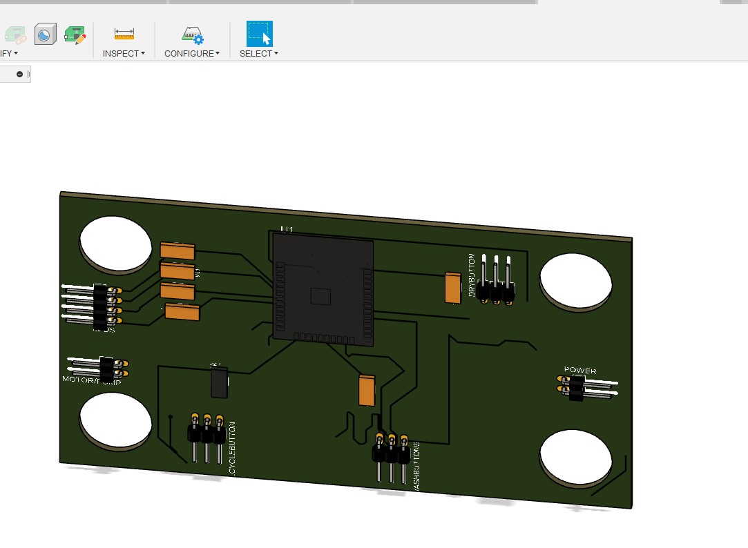
and the 3D view
Making a box and board #2
What I have found to be most confusing so far are libraries and which ones to use but I think that I bit more practice and this will become clearer
I decided to start over and this time use the ESP32 and focus what could be the board for my final project. Since I plan to break out the electronics to main board and break outs for LEDs, buttons etc. so the main board should have connectors set up.
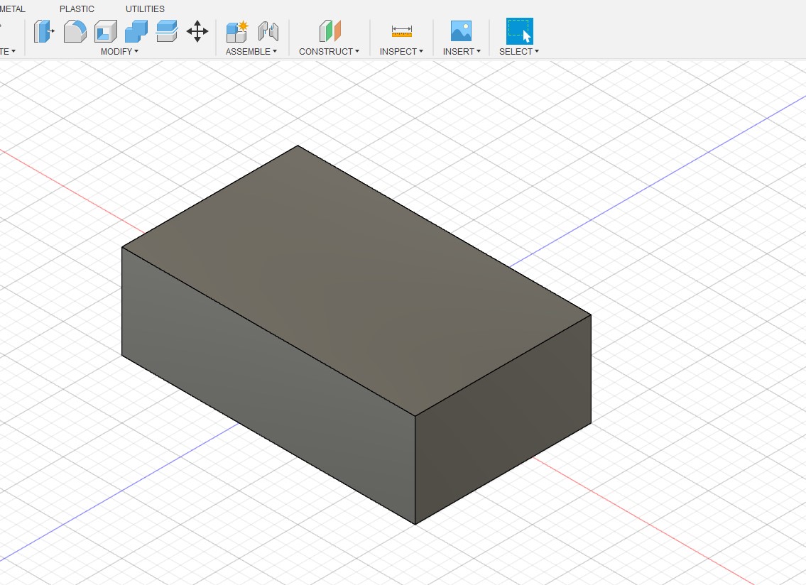
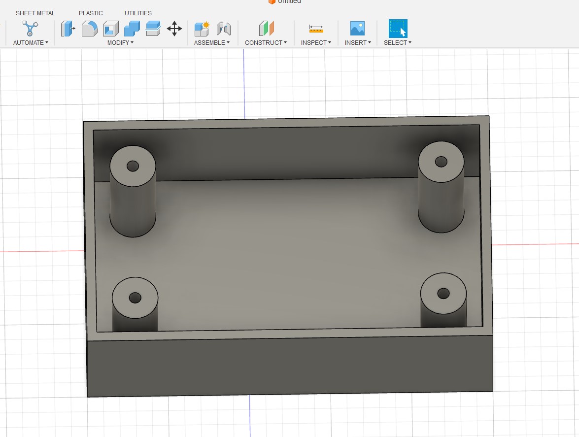
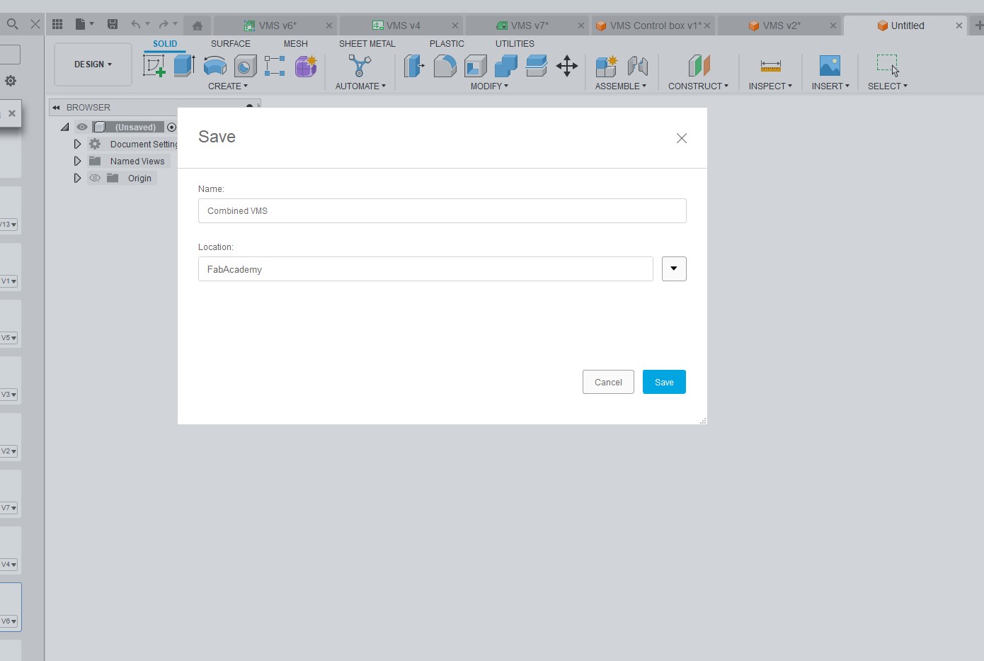
I started off by designing the box for the board
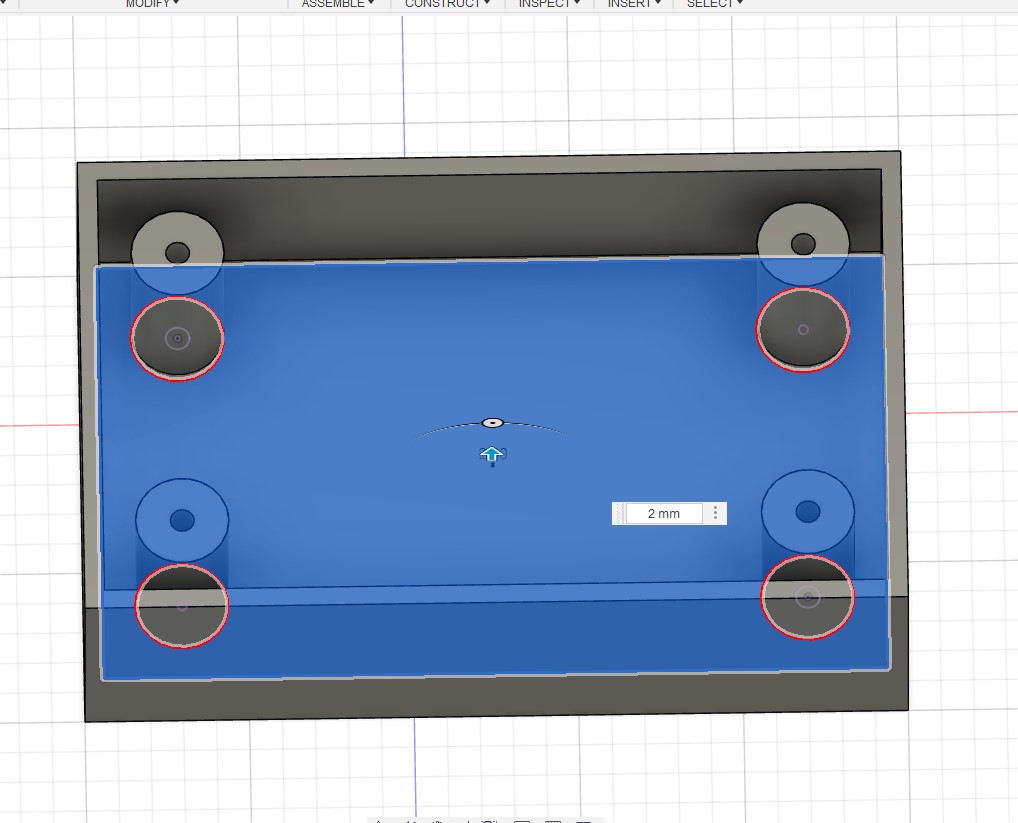
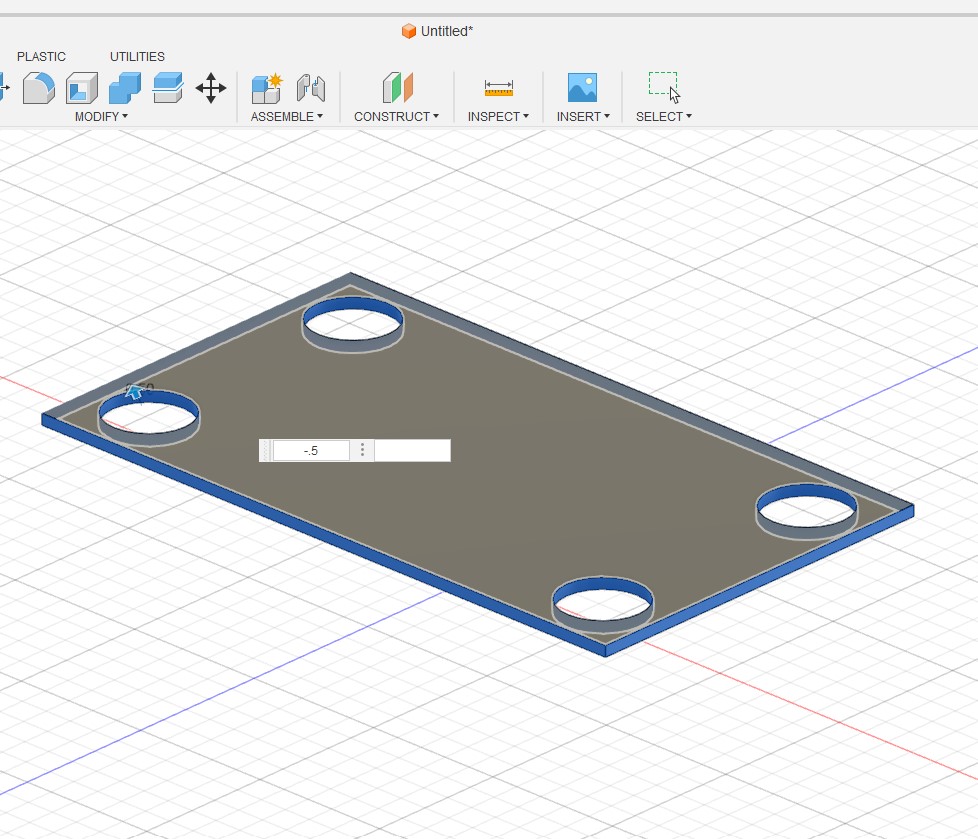
I then created the board profile
I connected it to the schematic
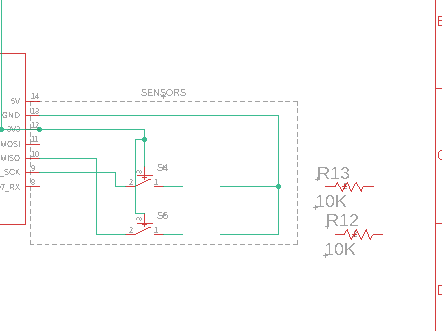
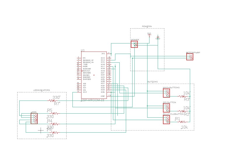
I got the connectors set up for the motor and water pump, operatings button including the pull down resistors LED indicators and power
I group and labeled everything
and started to place the components
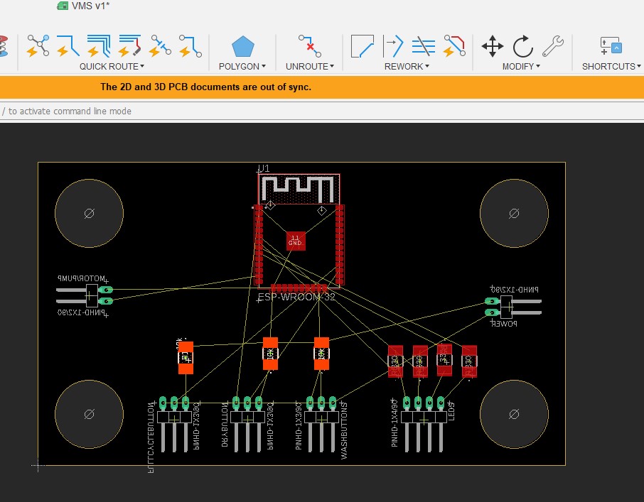
An routing .... however I hit road blocks with too many crossing connections
I took a 2 part approach both rewiring some of the connection by switching IO pins which did not matter to my code and moving some of the connection around on the board
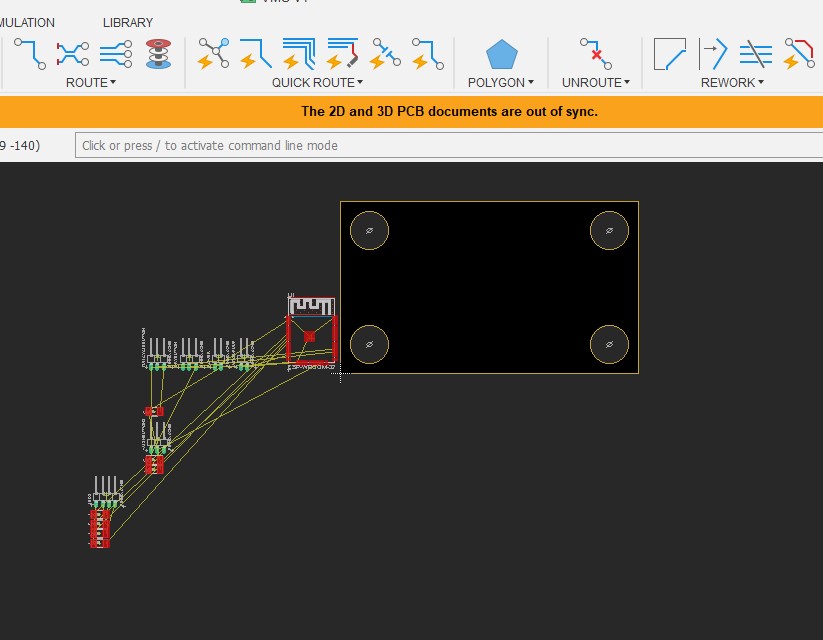
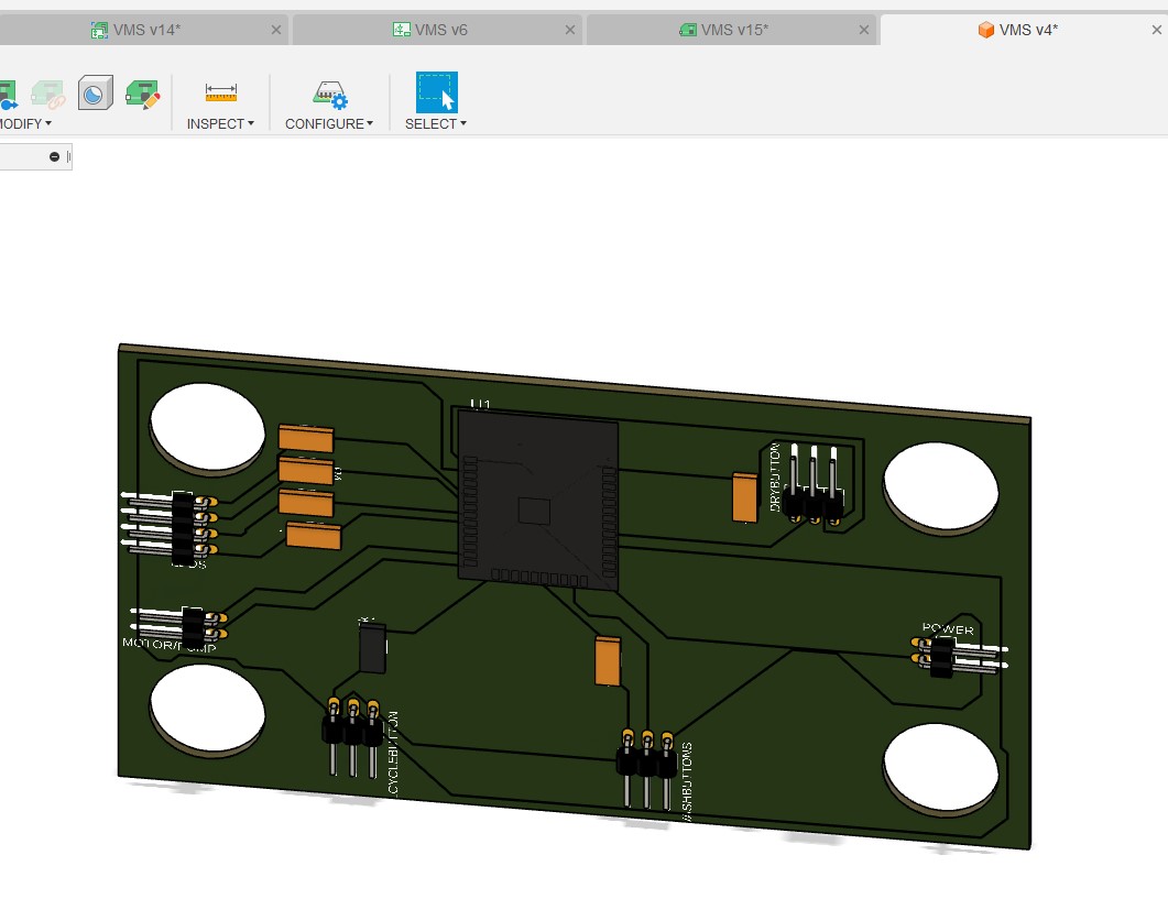
That allowed me to get everthing routed and pushed to 3D
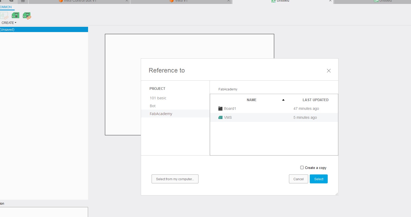
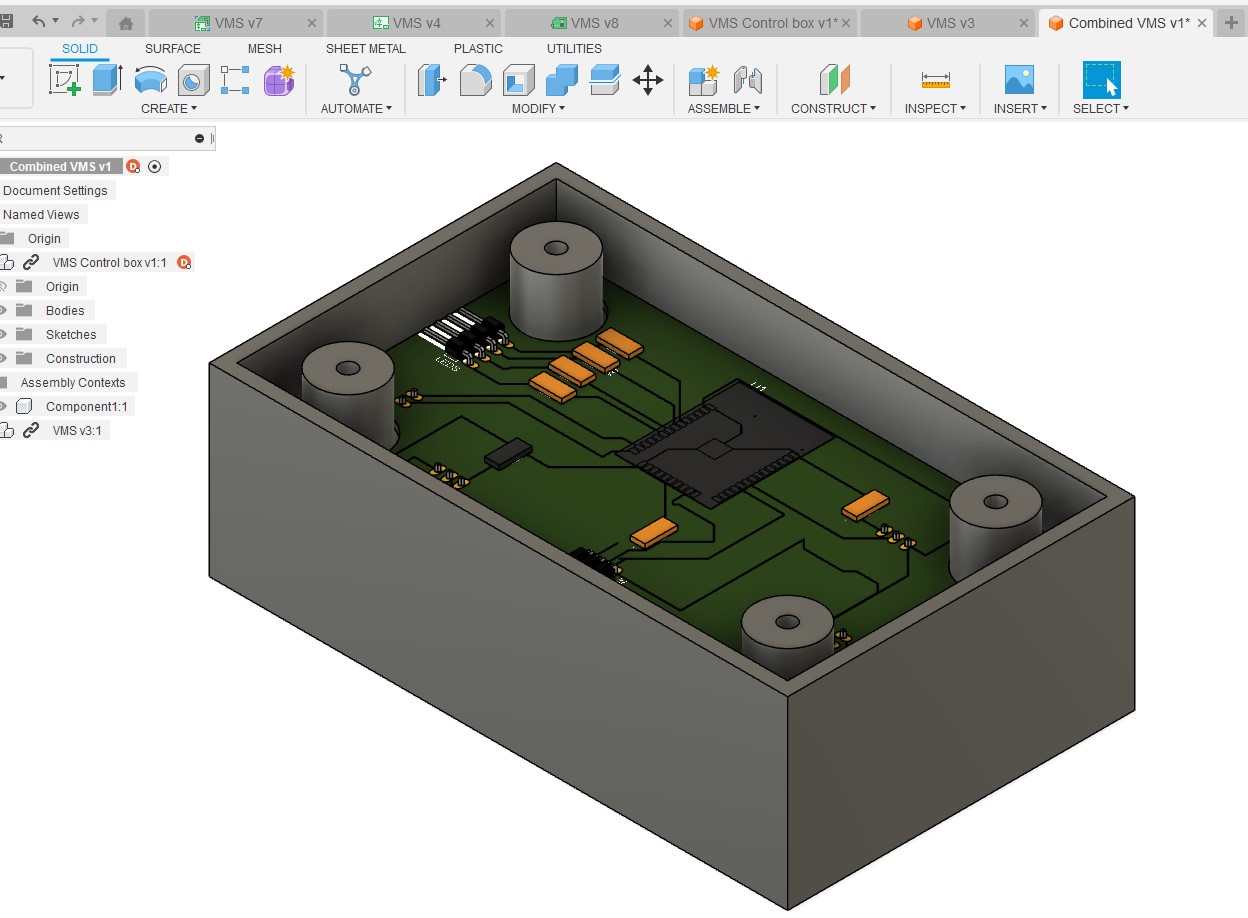
Now I wanted to see it in the box I created. So I made a new file so I can bring in the box and the board
I inserted the box
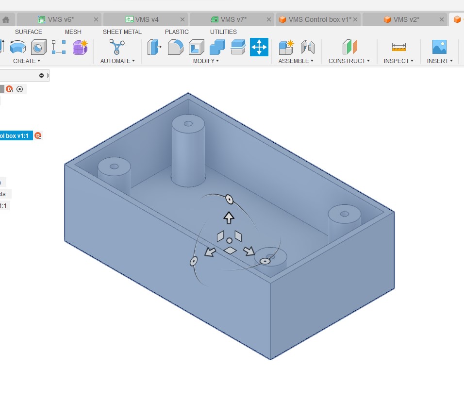
and the board
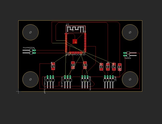
No when I move to 3D I noticed that moved a number of connectors to the wrong side and so after a bunch of research online I found out this was due to using the Mirror command the wrong way.
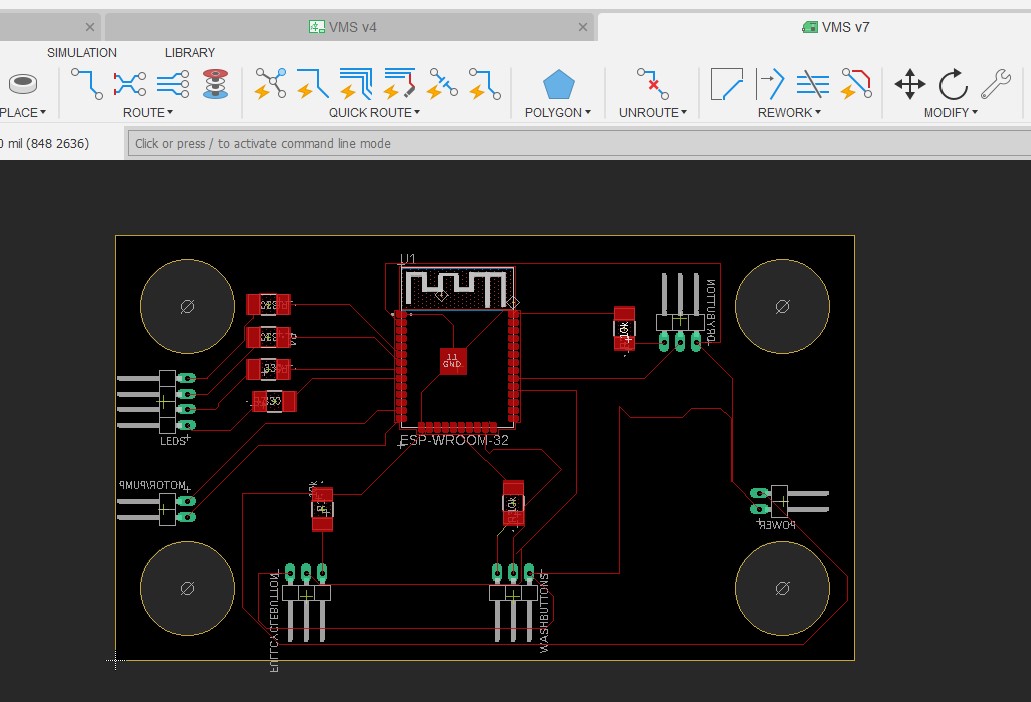
Now I had the components in the right side and had to reroute the components
I tweaked the schematic
and redid the view in the box
Here are my files for this week