10. Output Devices
Goals
Measure the power consumption of an output device. Document your work on the group work page and reflect on your individual page what you learned.
In our group assignment we measured the power consumption of a 12-24V / 80W motor I am planning to use in my final project. We did this by used an ESC and running the motor at minimum and top speed when powered by 12V, 13V, 14v, 15V and 16V. Our power supply showed us the power consumption for each combination. You can see our results here
Clearly these is a large range of power consumption by a single device such as a motor. We need to really understand the use case and workload that the motor will have to be able to plan the rest of the electronics and power supply successfully.
Individual assignment:
Add an output device to a microcontroller board you’ve designed and program it to do something.
Accomplishment
-
Set up the a servo (for locking mechanism) to be controlled by the board I designed last week
-
Designed a sub board to connect the servo (output device 1), button and 2 status LEDs (outputs 2 and 3)
-
Milling, stuffed and soldered the servo control board
-
Coded the microcontroller, connected the control boards and servo board and got it to work!!
5 Tackled a 4th output device - a spinning motor controled by and ESC
-
Designed my own solution for my micrcontroller to control the ESC
-
Use a transistor and a capacitor in my circuit design for the first time
-
Milled and soldered my Motor control sub board
-
Connected my Motor control board with main board
-
Hit a road black with transistor and wating for delivery of new batch to finish
ESP32 servo set up/test
My final project is a vegetable washing machine. It may be useful to lock the lid of the so that a user does not open it and get all when or get injured by stick his hand into the mechanism while it is spinning.
To do this I plan to use a servo motor and so I for this week I will start but have a button turn the servo 90 degrees to "lock" and another press will "unlock"
I start off by using my ESP32C3 control board i designed last week. You can find here
So I started off my work on my code and found out the that library for the servo on the ESP32C3 is different so I installed ServoESP32 library
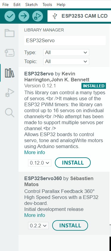
I then used the basic servo example for a sweep of 180 Degrees
#include <ESP32Servo.h>

// Define the pin number for the servo signal
const int servoPin = 5;

// Create a Servo object
Servo myservo;
int pos = 0;    // variable to store the servo position

void setup() {
  // Attach the servo to the pin
  myservo.attach(servoPin);
}

void loop() {
  // Move the servo to 90 degrees
  for (pos = 0; pos <= 180; pos += 1) { // goes from 0 degrees to 180 degrees
    // in steps of 1 degree
    myservo.write(pos);              // tell servo to go to position in variable 'pos'
    delay(15);                       // waits 15 ms for the servo to reach the position
  }
  for (pos = 180; pos >= 0; pos -= 1) { // goes from 180 degrees to 0 degrees
    myservo.write(pos);              // tell servo to go to position in variable 'pos'
    delay(15);                       // waits 15 ms for the servo to reach the position
}}
I hooked up the servo motor to my control board to test the code
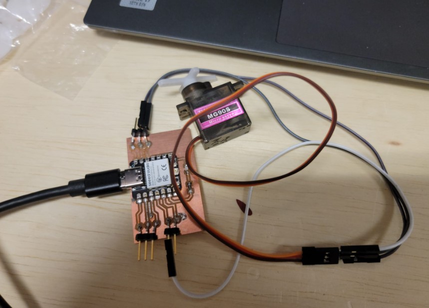
I used the onboard power to power the servo and then connector from the control pin (pin 5 in arduino)
And we have success
Locking mechanism servo board design
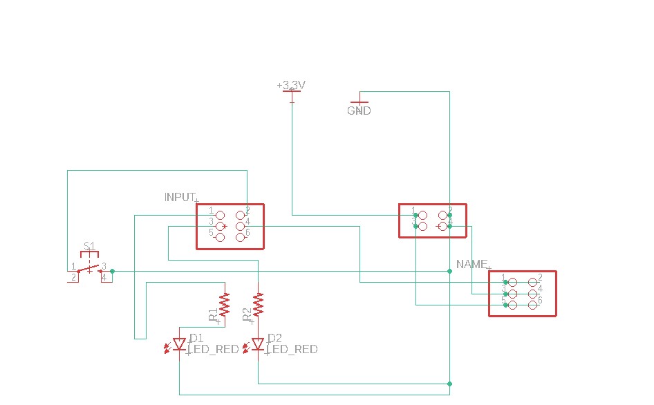
Now I wanted to make a sub board that will have a button, LED to show that the door is locking an provide power to the servo
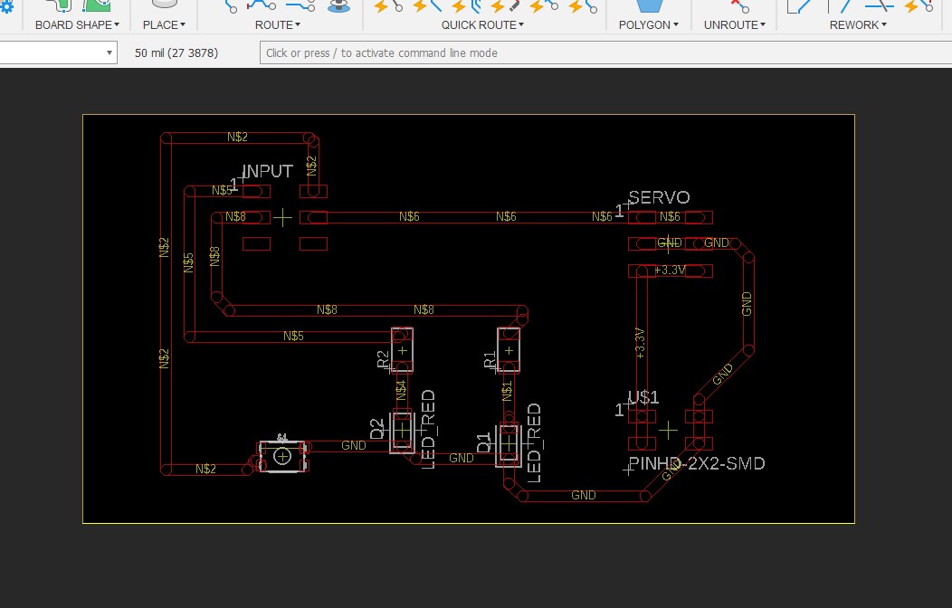
Here is my schematic
Started placing components
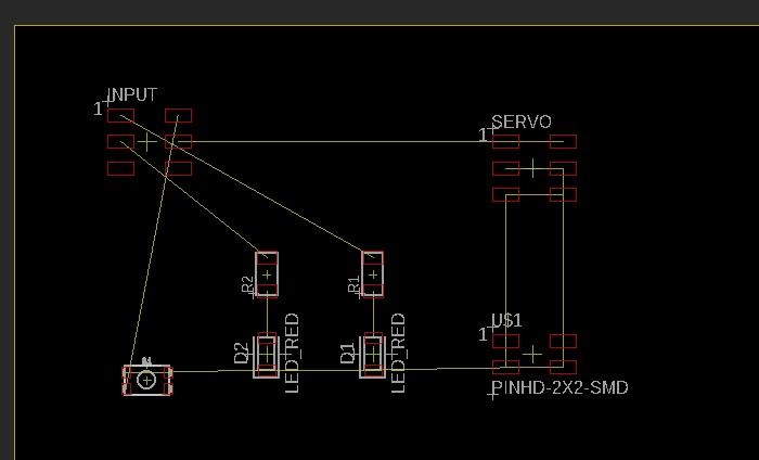
Added traces (extra thick ones)
Moved to 3D board to get tool path set up
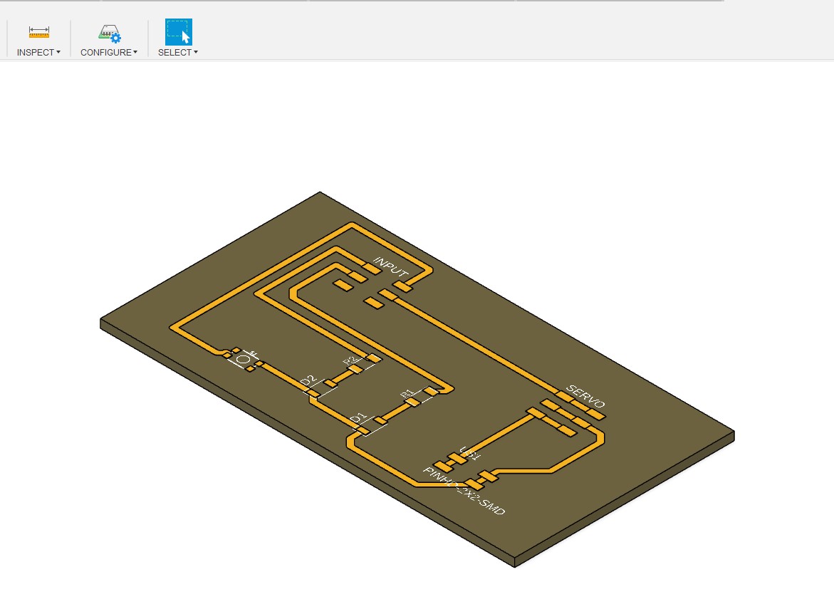
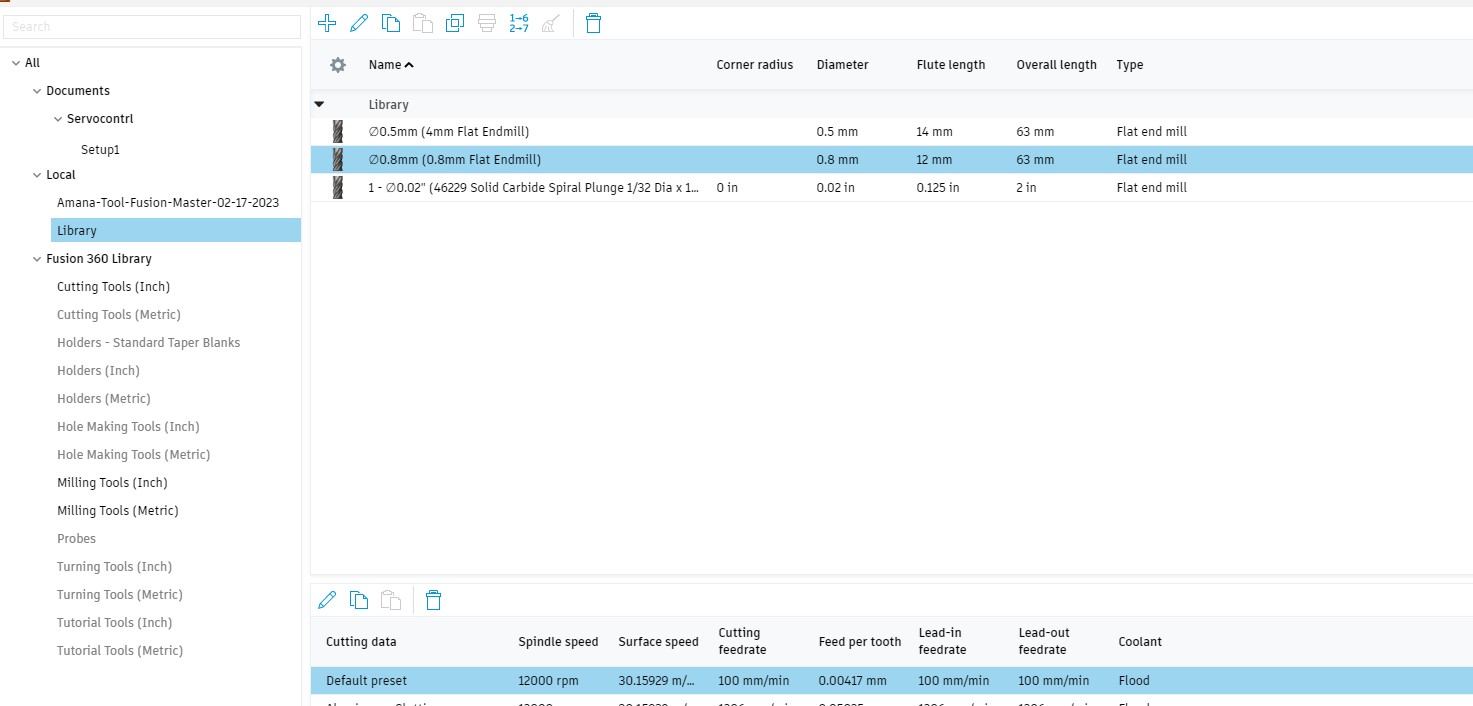
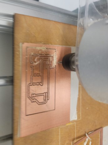
using a 0.8 mm endmill bit on the Genmitsu 3020-pro-max
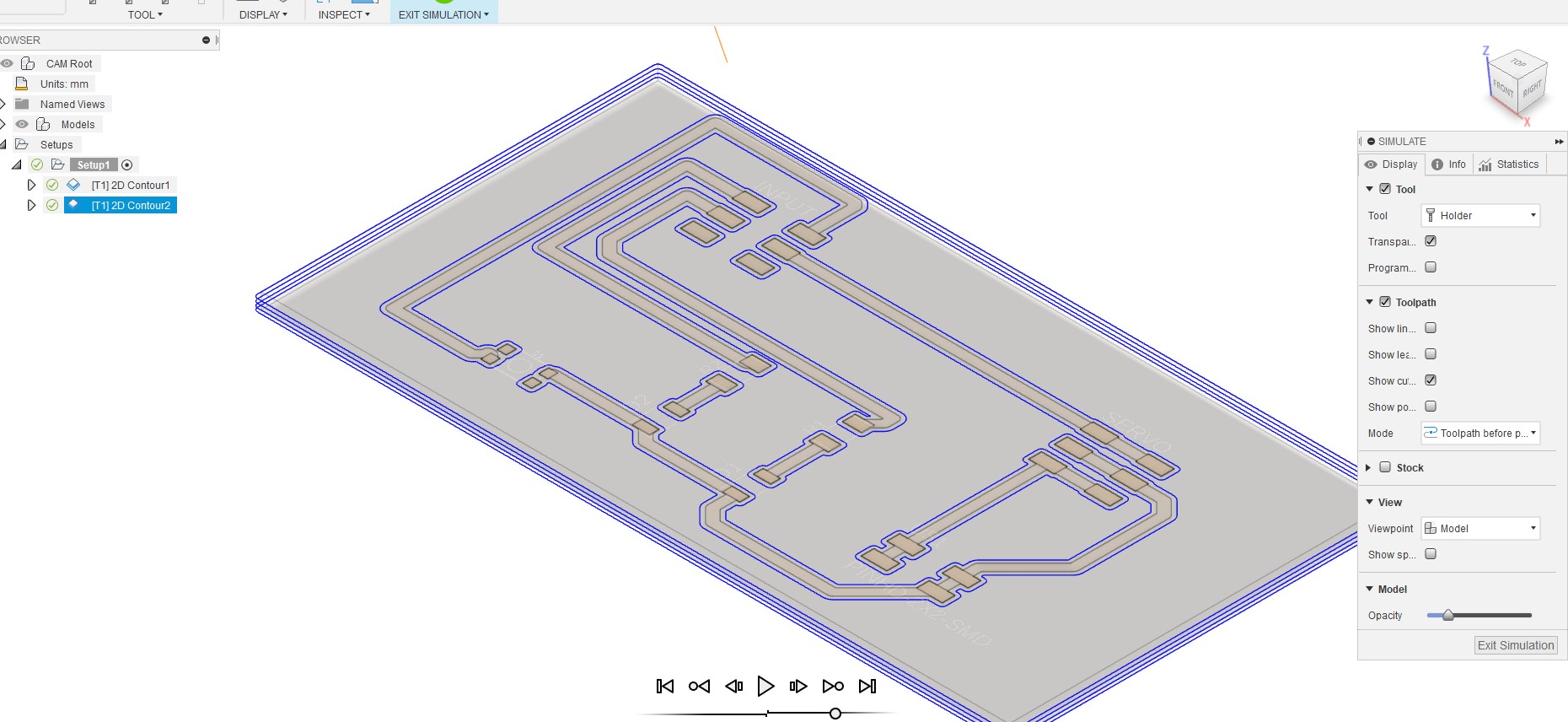
Simulation looks good ... time to mill
Milling servo board
Post porcess got the milling machine file set up
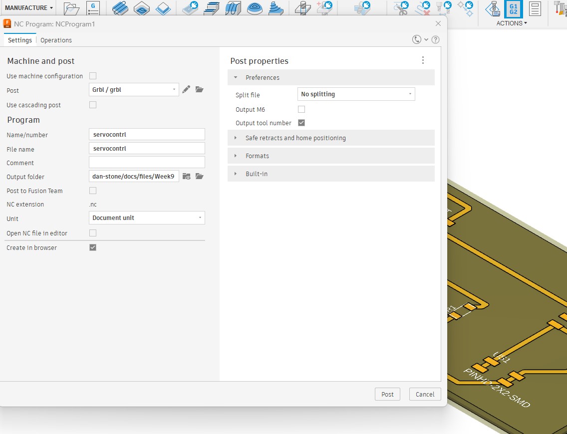
Looks good on the Candle SW used to control the milling machine
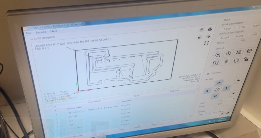
I set up the board and got the X,Y,Z zeroed
And we have a board I can start stuffing and soldering
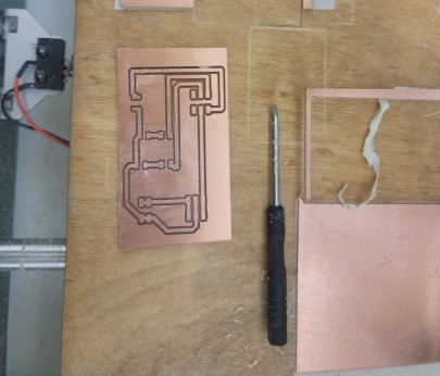
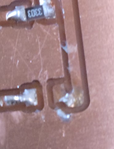
I started soldering but after getting the 2 resistors and LEDs in place I noticed that I was using a 330K resistors instead of the 330 by mistake
As i started to remove the resistor I stripped the board....
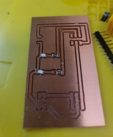
Milling machine was ready to go and 15min later I have a new board
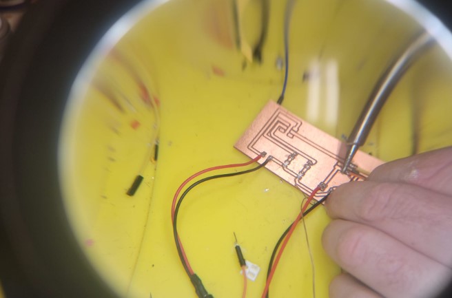
This time I take extra time to make sure I have everything in the right place and stuff and solder the board.
I also did not have enough connectors for both boards and so i had to use wires right off the board
Coding the servo
I am not sure about the mechanical lock set up and so for now I will just move the servo back and forth everytime I push the button. I use the following code
#include <ESP32Servo.h>

// Define the pin number for the servo signal
const int servoPin = 5;

// Create a Servo object
Servo myservo;
int pos = 0;    // variable to store the servo position
const int ledPin = 6;
const int ledPin2 = 3;
const int buttonPin = 2; // Change this to the GPIO number where the button is connected
const unsigned long interval = 1000;
unsigned long previousMillis = 0;
int flashCount = 0;
bool buttonPressed = false;

void setup() {
  // Attach the servo to the pin
  myservo.attach(servoPin);

  pinMode(ledPin, OUTPUT);
  pinMode(buttonPin, INPUT_PULLUP); // Enable the internal pull-up resistor for the button
  pinMode(ledPin, OUTPUT);
  pinMode(ledPin2, OUTPUT);

}

void loop() {

   if (digitalRead(buttonPin) == LOW) { // Check if the button is pressed
 digitalWrite(ledPin2,LOW);
 digitalWrite(ledPin,HIGH);
   for (pos = 0; pos <= 180; pos += 1) { // goes from 0 degrees to 180 degrees
    // in steps of 1 degree
    myservo.write(pos);              // tell servo to go to position in variable 'pos'
    delay(15);                       // waits 15 ms for the servo to reach the position
  }
  for (pos = 180; pos >= 0; pos -= 1) { // goes from 180 degrees to 0 degrees
    myservo.write(pos);              // tell servo to go to position in variable 'pos'
    delay(15);                       // waits 15 ms for the servo to reach the position
}
  } else {digitalWrite(ledPin,LOW); digitalWrite(ledPin2,HIGH);}

}
And we have success!!!
Here are the files for this week