5. Embedded Programming
This week we are starting off on the embedded programming topics.
Goals
Our group assignment was the compare different architecture of micro controller. It is clear to me that choosing the right micro controller is key given to a successful project. The different features, cost, speed form factor etc. will make your project either easier or harder and so taking the time to define that would work best is worth it
Individual:
-
Browse through the data sheet for your microcontroller
-
write program for a microcontroller development board to interact (with local input &/or output) and communicate (remotely)
extra credit: use different languages &/or development environments
extra credit: connect external components to the board
Accomplishments: I have had some experience working with Arduino and 412 in the fab academy prep session we have had and so I revisited the 412 for bare metal programming but focused mainly on the RP2040 and the Arduino.
- Reviewed the Data sheet for RP2040 and ESP32-s2
- Made a Morse Code "transmitter" using the RP2040 and C
- Used Micro python for the first time to make the RP2040 blink a LED
- Built a first cut at final project circuitry using the Arduino and C
- Tried out ChatGPT for some of the code development - got a basic structure in place but had to do clean up/changes
- Reviewed the 412 work we did in Prep week with input (Button Photo resistor) and outputs (LEDs)
- Wrote my first bare metal program for the ATTiny 412 to blink an LED
Reading the data sheets RP2040 / ESP32-S2
I reviewed through the data sheetS FOR RP2040 and the ESP32-s2. They are both ery dense and after reading the intro and skimming some of the other areas looking for answers to our group assignment some things start to look more familiar. Especially given the bare metal programming that reviewed in our Lab last week.
R2040 in C
I wanted to start with programming the R2040 to blink using C in the Arduino IDE and MicroPython
I got a set of parts and given the availability in our lab will use the Raspberry Pico for this excersize.
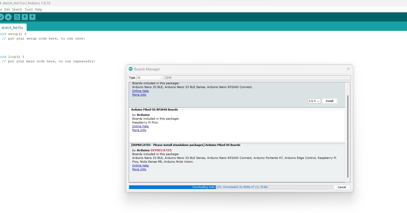
First added the RP2040 to the board manager in the Arudino IDE
I used the Blink built in example in Arudino
// the setup function runs once when you press reset or power the board
void setup() {
  // initialize digital pin LED_BUILTIN as an output.
  pinMode(LED_BUILTIN, OUTPUT);
}

// the loop function runs over and over again forever
void loop() {
  digitalWrite(LED_BUILTIN, HIGH);   // turn the LED on (HIGH is the voltage level)
  delay(1000);                       // wait for a second
  digitalWrite(LED_BUILTIN, LOW);    // turn the LED off by making the voltage LOW
  delay(1000);                       // wait for a second
}
I plugged the Pico in, complied and had the onboard led blinking
I wanted to add button and LED and so first off looked for the pinout map
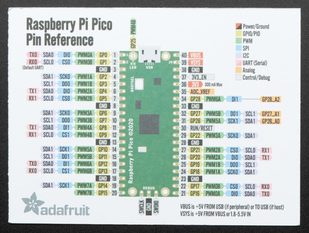
Then I connect the LED to the 20th leg. I change to the code to
// the setup function runs once when you press reset or power the board
void setup() {
  // initialize digital pin 20 as an output.
  pinMode(20, OUTPUT);
}

// the loop function runs over and over again forever
void loop() {
  digitalWrite(20, HIGH);   // turn the LED on (HIGH is the voltage level)
  delay(1000);                       // wait for a second
  digitalWrite(20, LOW);    // turn the LED off by making the voltage LOW
  delay(1000);                       // wait for a second
}
But no joy.....a few steps of trouble shooting and another look at the pinout map and i noticed I got confused between the physical leg number and the GPIO number and so quick correction replacing the 20 with 15
[void setup()  {
  // initialize digital pin 15 as an output.
  pinMode(15, OUTPUT);
}

// the loop function runs over and over again forever
void loop() {
  digitalWrite(15, HIGH);   // turn the LED on (HIGH is the voltage level)
  delay(1000);                       // wait for a second
  digitalWrite(15, LOW);    // turn the LED off by making the voltage LOW
  delay(1000);                       // wait for a second
And we are good!!
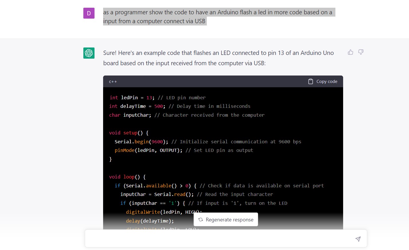
now for the input I decided to try 2 different things for the first time. Using the serial input and using Chat GPT as the starting point.
I gave chat ChatGPT the following prompt:
I did not see any of the morse code coming out in the code and so I went back and noticed my typo. I quick correction to the question and we have a better looking code
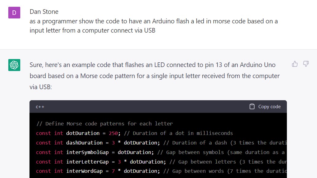
Here is the full code from Chat GPT
// Define Morse code patterns for each letter
const int dotDuration = 250; // Duration of a dot in milliseconds
const int dashDuration = 3 * dotDuration; // Duration of a dash (3 times the duration of a dot)
const int interSymbolGap = dotDuration; // Gap between symbols (same duration as a dot)
const int interLetterGap = 3 * dotDuration; // Gap between letters (3 times the duration of a dot)
const int interWordGap = 7 * dotDuration; // Gap between words (7 times the duration of a dot)
const char* morseTable[] = {
  ".-",   // A
  "-...", // B
  "-.-.", // C
  "-..",  // D
  ".",    // E
  "..-.", // F
  "--.",  // G
  "....", // H
  "..",   // I
  ".---", // J
  "-.-",  // K
  ".-..", // L
  "--",   // M
  "-.",   // N
  "---",  // O
  ".--.", // P
  "--.-", // Q
  ".-.",  // R
  "...",  // S
  "-",    // T
  "..-",  // U
  "...-", // V
  ".--",  // W
  "-..-", // X
  "-.--", // Y
  "--.."  // Z
};

int ledPin = 13; // LED pin number
char inputChar; // Character received from the computer
const char* morsePattern; // Morse code pattern for the input character

void setup() {
  Serial.begin(9600); // Initialize serial communication at 9600 bps
  pinMode(ledPin, OUTPUT); // Set LED pin as output
}

void loop() {
  if (Serial.available() > 0) { // Check if data is available on serial port
    inputChar = Serial.read(); // Read the input character
    inputChar = toupper(inputChar); // Convert input character to uppercase
    if (isalpha(inputChar)) { // Check if input is a letter
      morsePattern = morseTable[inputChar - 'A']; // Get the Morse code pattern for the input letter
      for (int i = 0; i < strlen(morsePattern); i++) { // Loop through the Morse code pattern
        if (morsePattern[i] == '.') { // If current symbol is a dot, turn on the LED for the duration of a dot
          digitalWrite(ledPin, HIGH);
          delay(dotDuration);
          digitalWrite(ledPin, LOW);
          delay(interSymbolGap);
        } else if (morsePattern[i] == '-') { // If current symbol is a dash, turn on the LED for the duration of a dash
          digitalWrite(ledPin, HIGH);
          delay(dashDuration);
          digitalWrite(ledPin, LOW);
          delay(interSymbolGap);
        }
      }
      delay(interLetterGap); // Add gap between letters
    } else if (inputChar == ' ') { // If input is a space, add gap between words
      delay(interWordGap);
    }
  }
}
I reviewed the code and it all seemed to make sense . I change the pin from 13 to 15 and gave it a try with both an "SOS" message and a "FAB". It works!!
RP2040 in Micropython
I do not know python so I first took a basic tutorial
I used the following direction to get Micropython loaded here and Thonny installed as an IDE here
No I ran through a basic python tutorial and it was straight forward.
Using the following code:
from machine import Pin, Timer

led = Pin(15, Pin.OUT)
timer = Timer()

def blink(timer):
    led.toggle()

timer.init(freq=2.5, mode=Timer.PERIODIC, callback=blink)
Here it is in action
Arduino and the Vegetable Washing Machine basic set up
To keep this week in sync with my final project I decided to test a set up for the basic VMS functionality replacing the water pump and motor with LED and the sensors with buttons.
Here is the functionality I was aiming for:
| Button | Label | FUnctionality |
|---|---|---|
| Button 1 | Wash cycle | 1. Check Lid / Water sensor -> 2. Turn on Water pump and motor for a set time |
| Button 2 | Dry cycle | 1. Check Lid -> 2. Turn on motor for a set time |
| Button 3 | Total cycle | 1. Run Wash cycle -> 2. Run Dry cycle |
| Sensors | If either sensor is triggered then stop and turn on error LED |
So I turned to ChatGPT and ask for the following:
"As a programmer write the code in Arduino for an RP 2040 to control a dishwasher. When you press button a the wash cycle will start checking the water level sensor making sure there's enough water, checking that the lid is shut, starting to spin the drum inside the washing machine and turning on the water pump for 60 seconds"
They generated a basic set of code.
// Define the pin numbers for the sensors and actuators
const int LED_PIN = 25;
const int BUTTON_PIN = 15;
const int WATER_SENSOR_PIN = 2;
const int LID_SENSOR_PIN = 3;
const int DRUM_PIN = 4;
const int WATER_PUMP_PIN = 5;

void setup() {
    // Initialize the RP 2040
    Serial.begin(9600);
    pinMode(LED_PIN, OUTPUT);
    pinMode(BUTTON_PIN, INPUT_PULLUP);
    pinMode(WATER_SENSOR_PIN, INPUT);
    pinMode(LID_SENSOR_PIN, INPUT);
    pinMode(DRUM_PIN, OUTPUT);
    pinMode(WATER_PUMP_PIN, OUTPUT);
}

void loop() {
    // Wait for the button press
    while (digitalRead(BUTTON_PIN) == HIGH) {
        digitalWrite(LED_PIN, LOW);
        delay(100);
        digitalWrite(LED_PIN, HIGH);
        delay(100);
    }

    // Check the water level and lid status
    if (digitalRead(WATER_SENSOR_PIN) == LOW && digitalRead(LID_SENSOR_PIN) == LOW) {
        // Start the wash cycle
        digitalWrite(DRUM_PIN, HIGH);
        digitalWrite(WATER_PUMP_PIN, HIGH);
        delay(60000);
        digitalWrite(DRUM_PIN, LOW);
        digitalWrite(WATER_PUMP_PIN, LOW);
    } else {
        Serial.println("Not enough water or lid is open.");
    }
}
I then decided to add dry and total cycles
"Now add a dry cycle that if we press a different button will spin slowly and then fast the drum for 120 seconds"
// Define the pin numbers for the sensors and actuators
const int LED_PIN = 25;
const int WASH_BUTTON_PIN = 15;
const int DRY_BUTTON_PIN = 14;
const int WATER_SENSOR_PIN = 2;
const int LID_SENSOR_PIN = 3;
const int DRUM_PIN = 4;
const int WATER_PUMP_PIN = 5;

void setup() {
    // Initialize the RP 2040
    Serial.begin(9600);
    pinMode(LED_PIN, OUTPUT);
    pinMode(WASH_BUTTON_PIN, INPUT_PULLUP);
    pinMode(DRY_BUTTON_PIN, INPUT_PULLUP);
    pinMode(WATER_SENSOR_PIN, INPUT);
    pinMode(LID_SENSOR_PIN, INPUT);
    pinMode(DRUM_PIN, OUTPUT);
    pinMode(WATER_PUMP_PIN, OUTPUT);
}

void loop() {
    // Wait for the wash button press
    if (digitalRead(WASH_BUTTON_PIN) == LOW) {
        // Check the water level and lid status
        if (digitalRead(WATER_SENSOR_PIN) == LOW && digitalRead(LID_SENSOR_PIN) == LOW) {
            // Start the wash cycle
            digitalWrite(DRUM_PIN, HIGH);
            digitalWrite(WATER_PUMP_PIN, HIGH);
            delay(60000);
            digitalWrite(DRUM_PIN, LOW);
            digitalWrite(WATER_PUMP_PIN, LOW);
        } else {
            Serial.println("Not enough water or lid is open.");
        }
    }

    // Wait for the dry button press
    if (digitalRead(DRY_BUTTON_PIN) == LOW) {
        // Start the slow spin
        digitalWrite(DRUM_PIN, HIGH);
        delay(10000);

        // Start the fast spin
        digitalWrite(DRUM_PIN, LOW);
        delay(1000);
        digitalWrite(DRUM_PIN, HIGH);
        delay(10000);
        digitalWrite(DRUM_PIN, LOW);
    }
}
and finally added a total
"Now add a full cycle button that will run the wash and then the dry cycle"
Here ChatGPT kept stopping in the middle and I had to prompt it to finish
// Define the pin numbers for the sensors and actuators
const int LED_PIN = 25;
const int WASH_BUTTON_PIN = 15;
const int DRY_BUTTON_PIN = 14;
const int FULL_BUTTON_PIN = 13;
const int WATER_SENSOR_PIN = 2;
const int LID_SENSOR_PIN = 3;
const int DRUM_PIN = 4;
const int WATER_PUMP_PIN = 5;

void setup() {
    // Initialize the RP 2040
    Serial.begin(9600);
    pinMode(LED_PIN, OUTPUT);
    pinMode(WASH_BUTTON_PIN, INPUT_PULLUP);
    pinMode(DRY_BUTTON_PIN, INPUT_PULLUP);
    pinMode(FULL_BUTTON_PIN, INPUT_PULLUP);
    pinMode(WATER_SENSOR_PIN, INPUT);
    pinMode(LID_SENSOR_PIN, INPUT);
    pinMode(DRUM_PIN, OUTPUT);
    pinMode(WATER_PUMP_PIN, OUTPUT);
}

void loop() {
    // Wait for the wash button press
    if (digitalRead(WASH_BUTTON_PIN) == LOW) {
        // Check the water level and lid status
        if (digitalRead(WATER_SENSOR_PIN) == LOW && digitalRead(LID_SENSOR_PIN) == LOW) {
            // Start the wash cycle
            digitalWrite(DRUM_PIN, HIGH);
            digitalWrite(WATER_PUMP_PIN, HIGH);
            delay(60000);
            digitalWrite(DRUM_PIN, LOW);
            digitalWrite(WATER_PUMP_PIN, LOW);
        } else {
            Serial.println("Not enough water or lid is open.");
        }
    }

    // Wait for the dry button press
    if (digitalRead(DRY_BUTTON_PIN) == LOW) {
        // Start the slow spin
        digitalWrite(DRUM_PIN, HIGH);
        delay(10000);

        // Start the fast spin
        digitalWrite(DRUM_PIN, LOW);
        delay(1000);
        digitalWrite(DRUM_PIN, HIGH);
        delay(10000);
        digitalWrite(DRUM_PIN, LOW);
    }

    // Wait for the full cycle button press
    if (digitalRead(FULL_BUTTON_PIN) == LOW) {
        // Perform the wash cycle
        if (digitalRead(WATER_SENSOR_PIN) == LOW && digitalRead(LID_SENSOR_PIN) == LOW) {
            // Start the wash cycle
            digitalWrite(DRUM_PIN, HIGH);
            digitalWrite(WATER_PUMP_PIN, HIGH);
            delay(60000);
            digitalWrite(DRUM_PIN, LOW);
            digitalWrite(WATER_PUMP_PIN, LOW);
        } else {
            Serial.println("Not enough water or lid is open.");
            return;
        }

        // Perform the dry cycle
        // Start the slow spin
        digitalWrite(DRUM_PIN, HIGH);
        delay(10000);

        // Start the fast spin
        digitalWrite(DRUM_PIN, LOW);
        delay(1000);
        digitalWrite(DRUM_PIN, HIGH);
        delay(10000);
        digitalWrite(DRUM_PIN, LOW);
    }
}
Reviewing the code there were a number of things I wanted to change:
-
Pin numbers - I decided to use the Arduino and so change the pin numbers
-
Button functionality - I wanted to trigger the cycle when button is pressed and there for input would be HIGH. For some reason ChatGPT used INPUT_PULLUP when would do the opposite so I adjusted that
-
No sensor checks for Dry cycle or total - added those + changed the trigger from low to high
-
Decided to have LED flashing rather then "fast/low spin" and reduce the time for the sake of our test
-
Add a error led to the sensor trigger
Here is my updated code:
// Define the pin numbers for the sensors and actuators
const int LED_PIN = 7;
const int WASH_BUTTON_PIN = 11;
const int DRY_BUTTON_PIN = 10;
const int FULL_BUTTON_PIN = 9;
const int WATER_SENSOR_PIN = 2;
const int LID_SENSOR_PIN = 3;
const int DRUM_PIN = 4;
const int WATER_PUMP_PIN = 5;

void setup() {
    Serial.begin(9600);
    pinMode(LED_PIN, OUTPUT);
    pinMode(WASH_BUTTON_PIN, INPUT);
    pinMode(DRY_BUTTON_PIN, INPUT);
    pinMode(FULL_BUTTON_PIN, INPUT);
    pinMode(WATER_SENSOR_PIN, INPUT);
    pinMode(LID_SENSOR_PIN, INPUT);
    pinMode(DRUM_PIN, OUTPUT);
    pinMode(WATER_PUMP_PIN, OUTPUT);
}

void loop() {
    // Wait for the wash button press
    if (digitalRead(WASH_BUTTON_PIN) == HIGH) {
        // Check the water level and lid status
        if (digitalRead(WATER_SENSOR_PIN) == LOW && digitalRead(LID_SENSOR_PIN) == LOW) {
            // Start the wash cycle
            digitalWrite(DRUM_PIN, HIGH);
            digitalWrite(WATER_PUMP_PIN, HIGH);
            delay(600);
            digitalWrite(DRUM_PIN, LOW);
            digitalWrite(WATER_PUMP_PIN, LOW);
              delay(400);
              digitalWrite(WATER_PUMP_PIN, HIGH);
           delay(400);
            digitalWrite(WATER_PUMP_PIN, LOW);
        } else {
            Serial.println("Not enough water or lid is open.");
                        digitalWrite(LED_PIN, HIGH);

        }
    }

    // Wait for the dry button press
    if (digitalRead(DRY_BUTTON_PIN) == HIGH) {
        // Start the slow spin
                if (digitalRead(LID_SENSOR_PIN) == LOW) {

        digitalWrite(DRUM_PIN, HIGH);
        delay(600);

        // Start the fast spin
        digitalWrite(DRUM_PIN, LOW);
        delay(300);
        digitalWrite(DRUM_PIN, HIGH);
        delay(300);
        digitalWrite(DRUM_PIN, LOW);
                }     else {
            Serial.println("lid is open.");
                        digitalWrite(LED_PIN, HIGH);

        }
    }

    // Wait for the full cycle button press
    if (digitalRead(FULL_BUTTON_PIN) == HIGH) {
        // Perform the wash cycle
        if (digitalRead(WATER_SENSOR_PIN) == LOW && digitalRead(LID_SENSOR_PIN) == LOW) {
            // Start the wash cycle
            digitalWrite(DRUM_PIN, HIGH);
            digitalWrite(WATER_PUMP_PIN, HIGH);
            delay(600);
            digitalWrite(DRUM_PIN, LOW);
            digitalWrite(WATER_PUMP_PIN, LOW);
                delay(400);
            digitalWrite(WATER_PUMP_PIN, HIGH);
           delay(400);
            digitalWrite(WATER_PUMP_PIN, LOW);
        } else {
            Serial.println("Not enough water or lid is open.");
             digitalWrite(LED_PIN, HIGH);
            return;
        }

        // Perform the dry cycle
        // Start the slow spin
        if (digitalRead(LID_SENSOR_PIN) == LOW) {
        digitalWrite(DRUM_PIN, HIGH);
        delay(200);

        // Start the fast spin
        digitalWrite(DRUM_PIN, HIGH);
        delay(200);
        digitalWrite(DRUM_PIN, LOW);
        delay(200);
        digitalWrite(DRUM_PIN, HIGH);
        delay(100);
        digitalWrite(DRUM_PIN, LOW);

       } else {
            Serial.println("Not enough water or lid is open.");
             digitalWrite(LED_PIN, HIGH);
            return;
        }

    }}
Here is the basic circuit I am planning
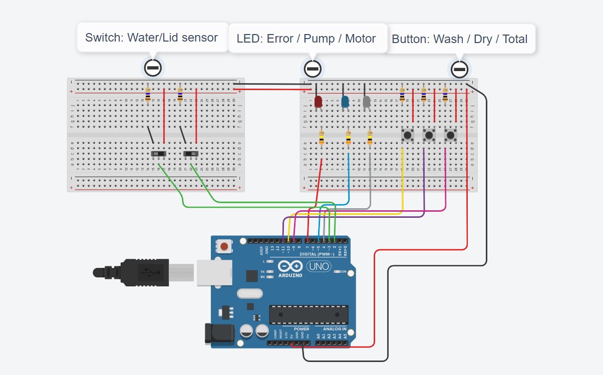
I followed this diagram (except for the different colored wires) and it went pretty smoothly
Here is the one I built in action:
412 Blinking and Button and Photo resistor
We covered this in the Fab Academy prep 412 documentation
412 Bare metal blinking
I start off by getting my Arudino Uno loaded with JTAG based on the same process I documented in Fab Prep week
Once I have that set up, I reviewed the lecture we had in class and watch a number of tutorials about bare metal programing
I looked up the pinout map for the ATTiny412
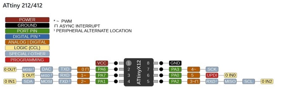
Now it was time to start the coding
Based on the map and the ATTiny I wanted to take the Blink code and start replacing some of the code turning PIN2 to out put and then turning it one and off
Here is the starting code:
void setup() {
  // initialize digital pin LED_BUILTIN as an output.
  pinMode(1, OUTPUT);
}

// the loop function runs over and over again forever
void loop() {
  digitalWrite(1, HIGH);   // turn the LED on (HIGH is the voltage level)
  delay(1000);                       // wait for a second
  digitalWrite(1, LOW);    // turn the LED off by making the voltage LOW
  delay(1000);                       // wait for a second
}
To start off I replaced
pinMode(2, OUTPUT); with DDRB = 1; based on many of the example I have seen however it seemed the DDRB was not recognized....a LOT of googleing later I found out that for 412 the code is differnt then for the Ardunio and I need to use PORT.DIR;
So I set up PORT.DIR = 1; and....no blinking.
Reviewing the lecture and discuss with a class mate I was reminded that this is index 0 so PA1 is actualy the second slot and so I need to set it to 2 to turn on, not 1.
PORT.DIR = 2;
worked!
Now to replace digitalWrite(1, HIGH);
For the 412 I needed to us PORTA.OUT = 2; which again was differnt then the other examples and so here is the final code I used:
void setup() {
  // initialize digital pin LED_BUILTIN as an output.
 PORTA.DIR = 1;
}

// the loop function runs over and over again forever
void loop() {
  PORTA.OUT = 2;   // turn the LED on (HIGH is the voltage level)
  delay(200);                       // wait for a second
  PORTA.OUT = 0;   // turn the LED on (HIGH is the voltage level)
  delay(200);                       // wait for a second
}
Here are the files from this week work
Vegetable Washing Machine V1.0 Code