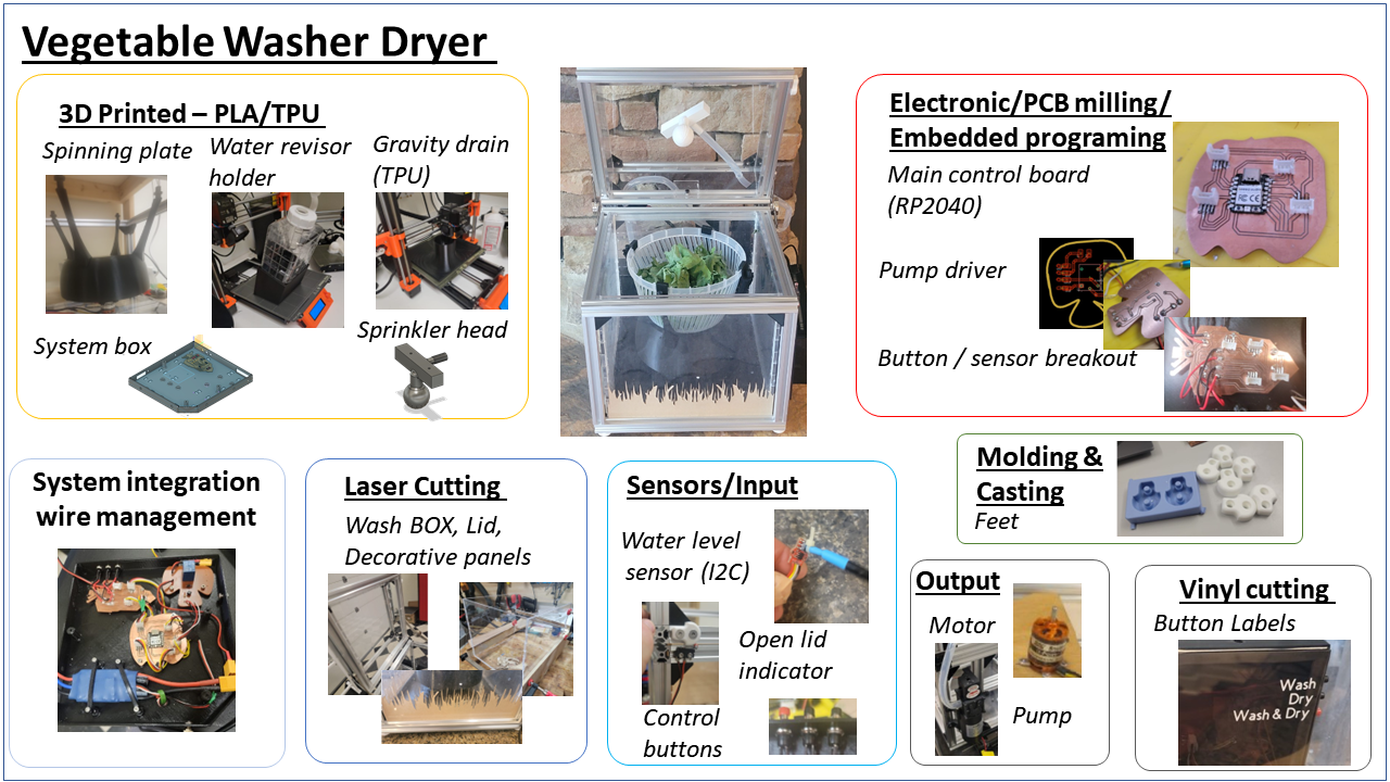
Final Project
My project is a vegetable washing machine
Research
What will it do?
Goal is to create a kitchen appliance that can wash and dry greens and other vegetables via a pre set cycle both saving time (and potentially water)
Who's done what beforehand?
So far I only found limited similar project within the fab academy community and a few outside.
Fab Academy projects
1) here
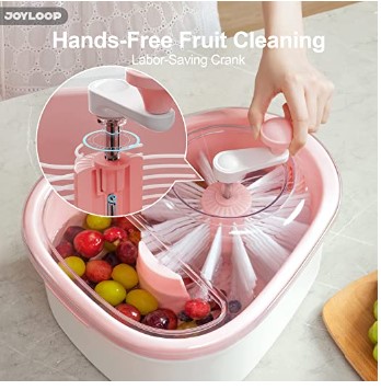
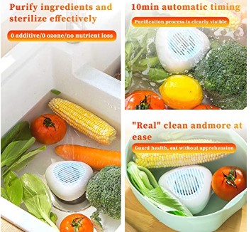
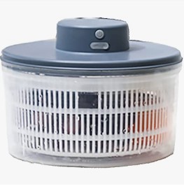
Outside of fab academy:
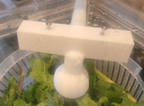
- I like the automated spinning salad dryer that the You Tuber The Practical Engineer designed
I think that he has a good spinner design and using this approach can allow me to allow users to put in any colander they wish.
- Commercial solution are mainly ultrasonic, manual or focused on drying (salad spinners)
Here are some examples
What will you design? I will design all aspect of the project with 4 major components
1) The box / frame of the machine and water reservoir
2) The spinning mechanism
3) The machine lid and water dispensing mechanism
4) Control board electronics - main board, pump breakout board, motor breakout board, button breakout board
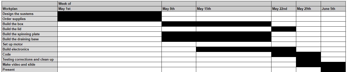
Here is a basic work plan for the final build
What materials and components will be used?
The main materials are 1) T Rails + Plexiglass
2) 3D print filament - TPU, PLA and XTC3D finishing resin
3) Electronic components and PCB boards, motor/ESC and pump
4) Molding plastic / rubber
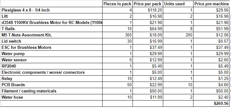
Below is a full BOM
You can find the link to the suppliers in the attached file
Where will come from?
Most are either provided by lab, purchased from Digi key or Amazon
How much will they cost?
What parts and systems will be made?
Washbasin/box/frame, drain/skirt, spinning plate, lid, water reservoir, electronics boards.
Only things not made are: Motor + ESC, pump, salad spinner bowl, water tube, sprinkler head, power supply
What processes will be used? - 3D print - Laser cutting - PCB Board milling - Molding and casting / resin - System integration
What questions need to be answered?
- Spinning mechanism - chain/band vs. direct drive (already answered)
- Frame materials - (already answered - TRail )
- Water drainage approach - TPU printed sloped base
How will it be evaluated?
- does it wash and clean greens / veggies
Under what license is the project
The project is published under the Creative Commons Attribution-NonCommercial 4.0 International License
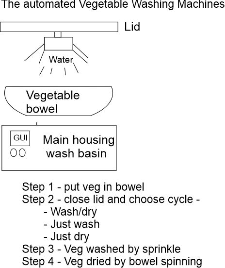
Project description
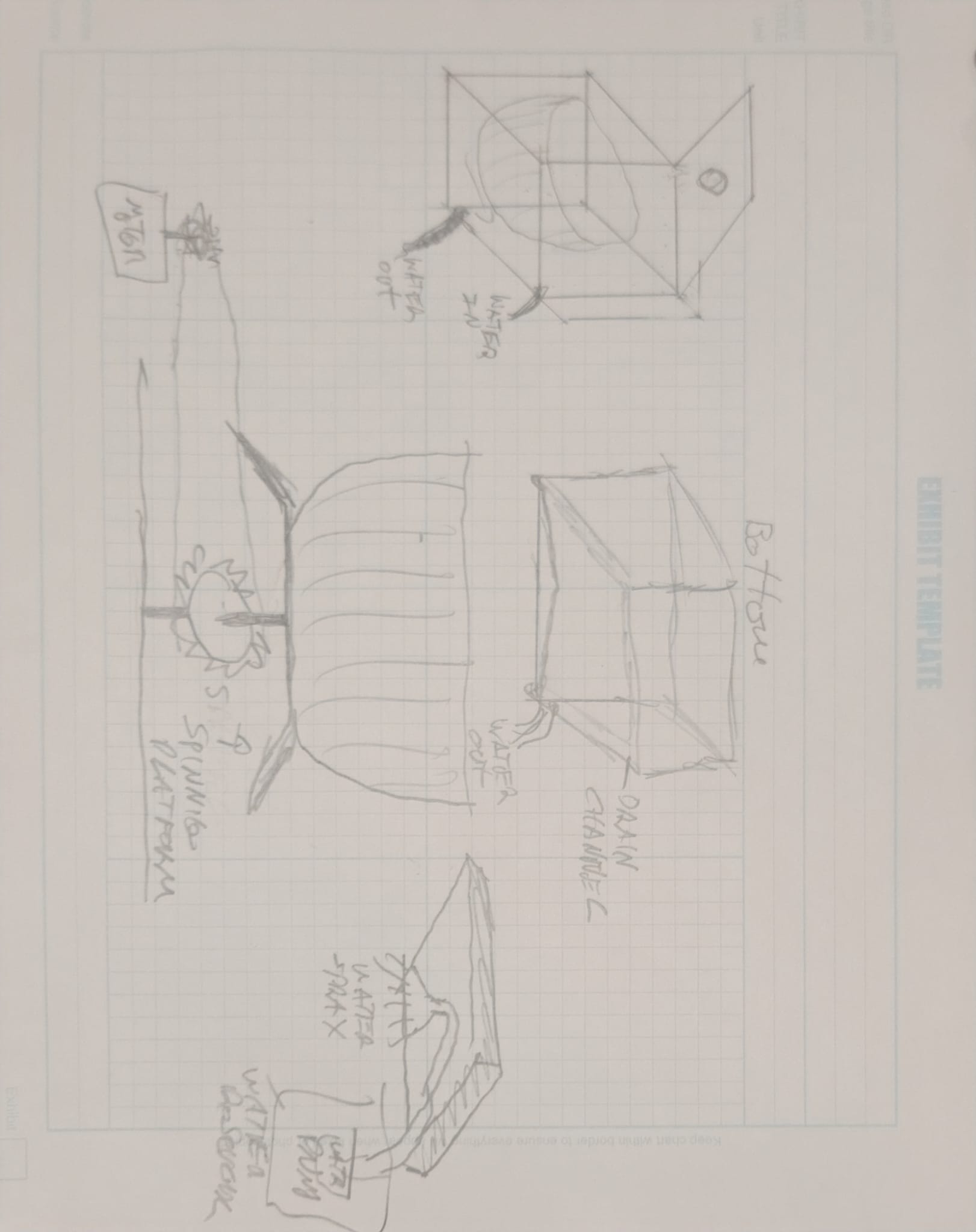
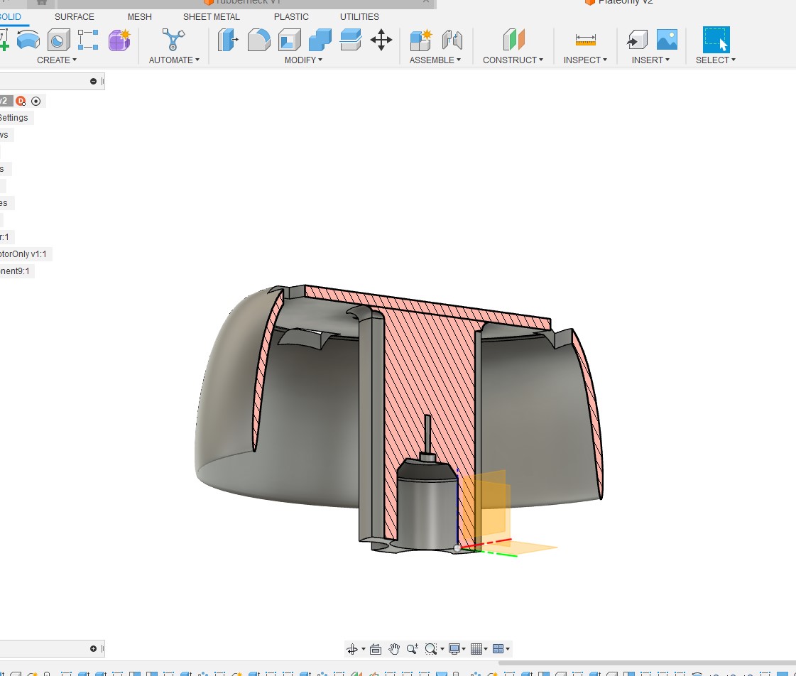
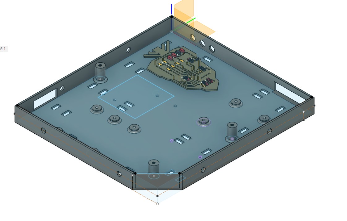
Here is a first cut at the base:
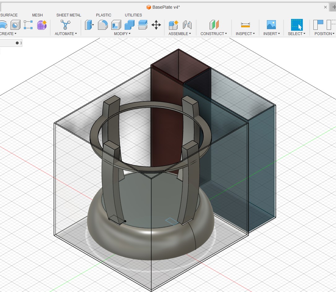
There are 4 main parts to the appliance
-
Water reservoir
-
Main container (Wash basin)- base is designed to have a gravity fed drain
-
Lid with build in sprinkler
-
Vegetable holding bowel that sites in the Wash basin and spins to dry
There are 2 Motor/pump used
-
Water pump to move water from reservoir to sprinkler head
-
Motor to spin Vegetable bowel
There are 2 potential sensors
-
Lid sensor - stop operation if lid is open mid cycle
-
Water level sensor to alert if reservoir is empty
Microcontroller usage
-
Control sequencing of pumps / motors
-
Interrupt operation if sensor is triggered
-
Manage GUI
GUI
-
Button that allow user to start cycle
-
Wash only
-
Dry only
-
Wash/dry
-
Announce alerts (ready/water empty/finished)
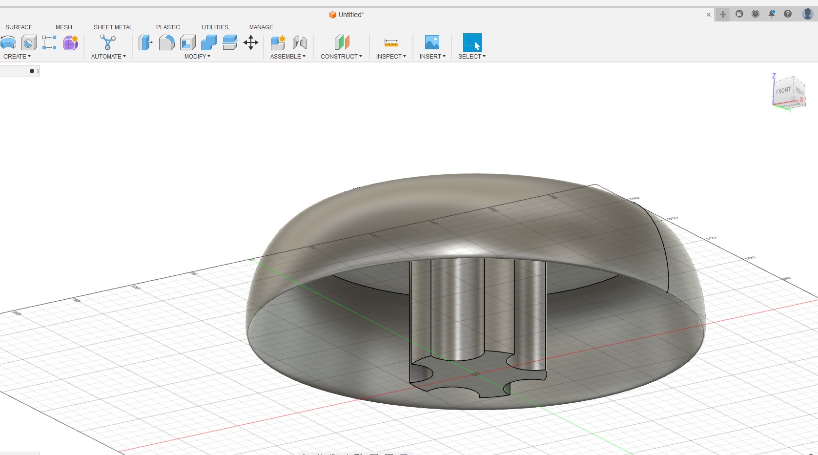
Here is a another view of the merging design

Project: Align parts to Fab Academy weekly topics
| Weekly topics | Parts |
|---|---|
| Computer controlled cutting | Outbox / wash basin holder |
| Electronics production | Controller, motor ESC, Sensors |
| 3D Scanning and printing | Motor housing, water connectors, sprinkler head, sproket/chain for motor drive |
| Electronics design | sensors / controller board / Motor ESC |
| Computer controlled machining | Controller board |
| Embedded programming | Cycle design / User input |
| Molding and casting | Drain / Spinning plate |
| Input devices | GUI buttons / Sensors |
| Output devices | Screen |
Key component breakdown
Wash basin and lid - Laser cut plexiglass
Outer box - T-rails
Water reservoir holder - 3D print (PLA)
Electronic housing - 3D print box (PLA) / Laser cut cover
Sprinkler - 3D print (PLA)
Box base/drain/motor protective skirt - 3D print (TPU)
Controller board / Pump driver / button and sensor break out board - PCB milling
Sensors - 1) Lid sensor 2) Water level sensor
Machine feet - Molding and casting
Power supply box - Laser cut plexiglass
Purchased - ESC, motor, pump, power supply, water bottle/reservoir, spinner bowel
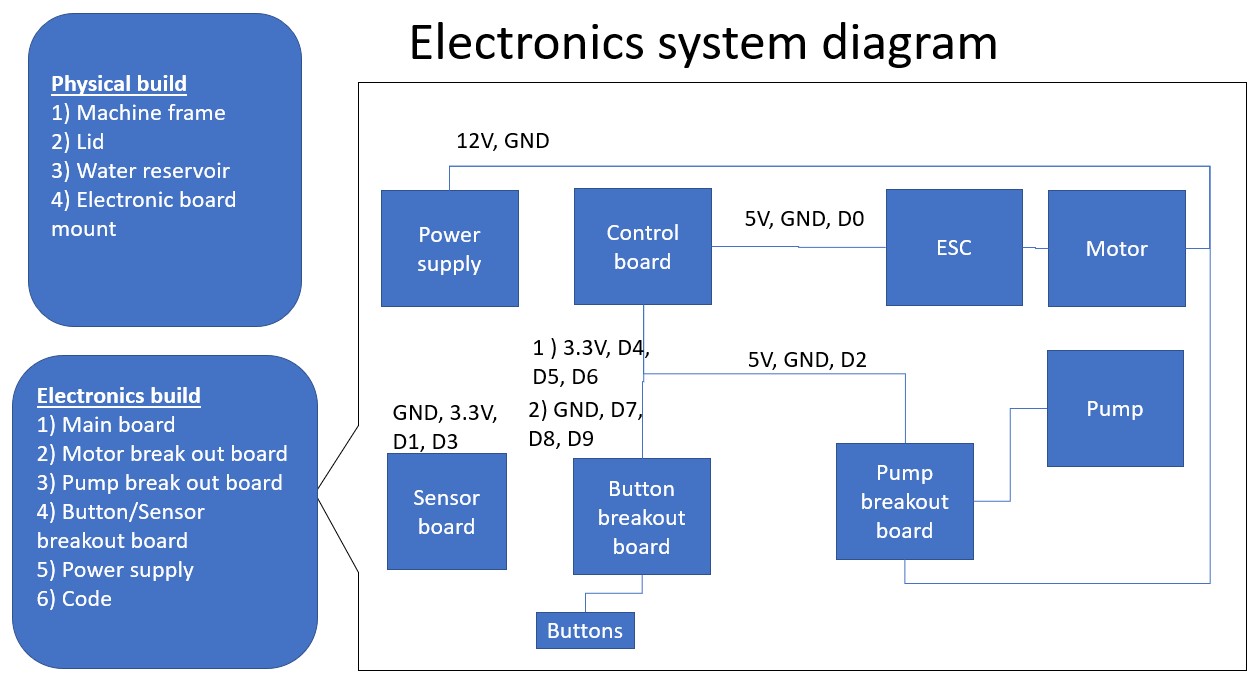
Project: Build / system overview
My build split into the physical build and the electronics with notation of pins connected to each breakout board.
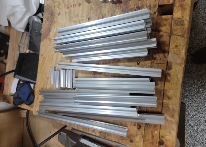
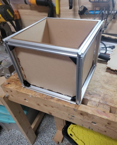
Box: Frame build
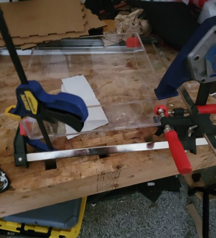
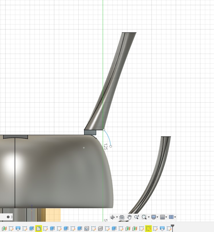
I decided to use a similar method that we used in machine week of T rails for the outside frame and then 1/4 inch plexiglass for the water tight box and water reservoir that are both mounted in side the frame
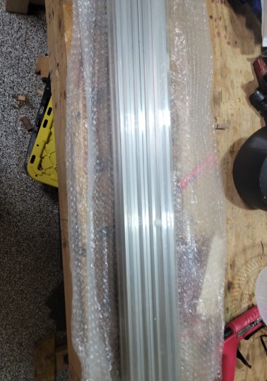
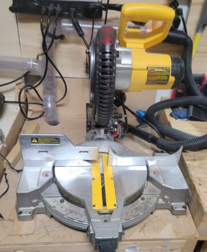
Using a chop saw and aluminum cutting blade I got all the pieces ready for assembly
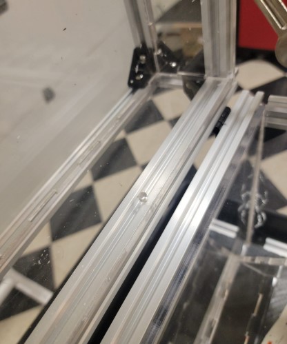
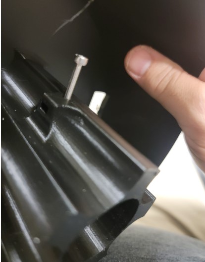
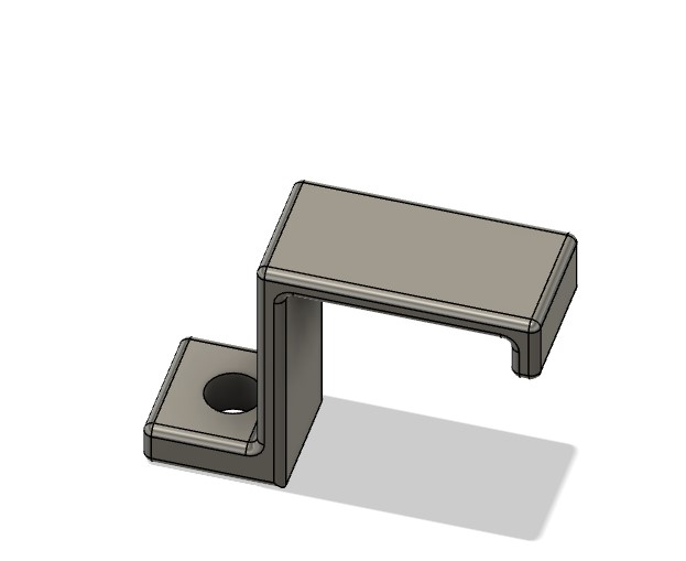
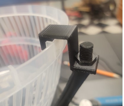
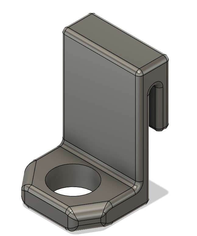
3D printed bracket will be key together with T Rail M5 screws and bolts
You can see the bracket in action
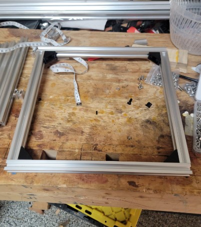
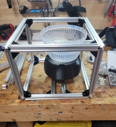
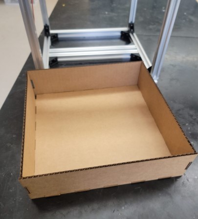
Assembly of the box was straight forward
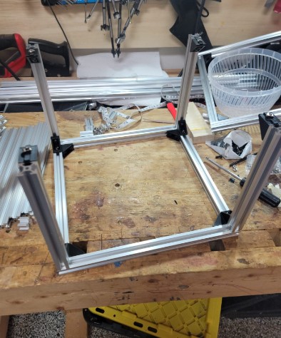
COnfirming the size with spinning plate and bowel
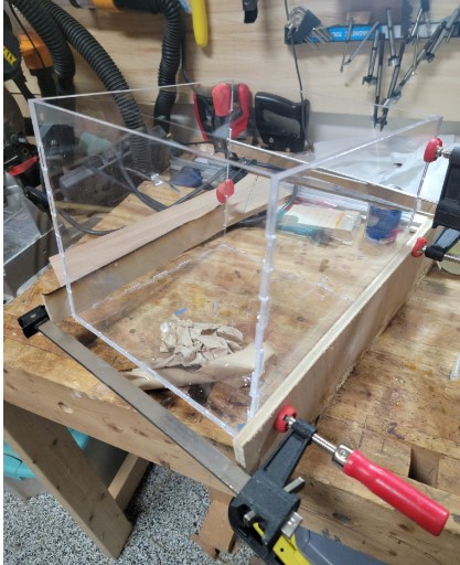
To make the water proof interior box I decided to use 1/4 plexiglass that I will laser cut and then use cement and possible silicon to water proof
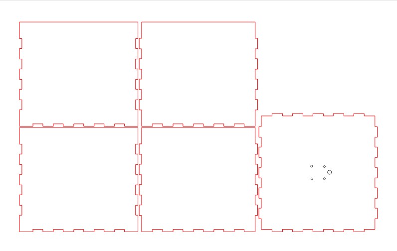
I used the big epilog laser at the fab lab. Setting for 1/4 inch plexi glass was 100% power and 10% speed.
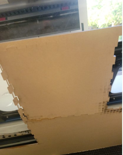
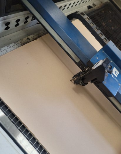
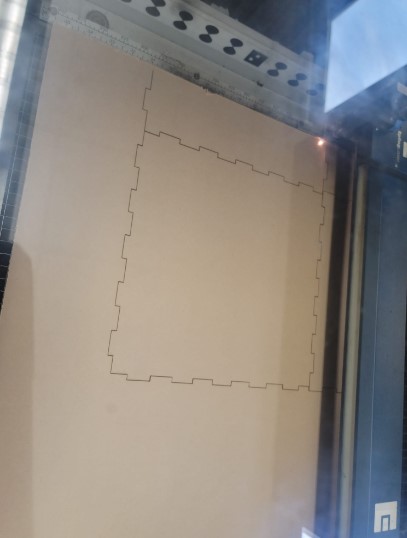
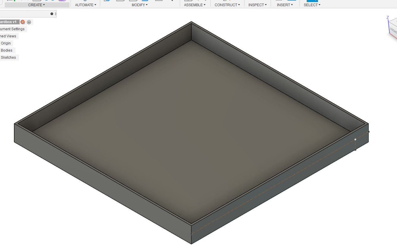
I first cut and assembled a cardboard set to make sure it all worked well as I only have 1 sheet of plexiglass. I made sure the mounting holes for the motor were positioned correctly

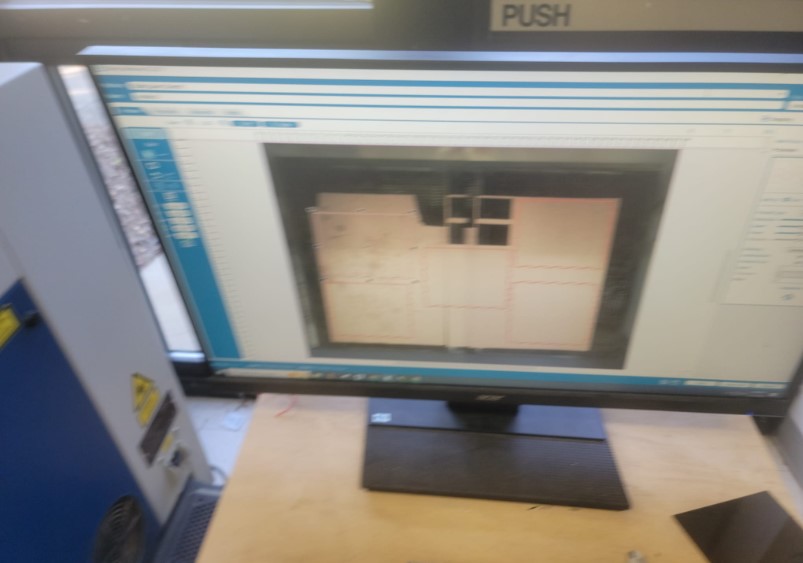
Now it was time to cut the plexiglass
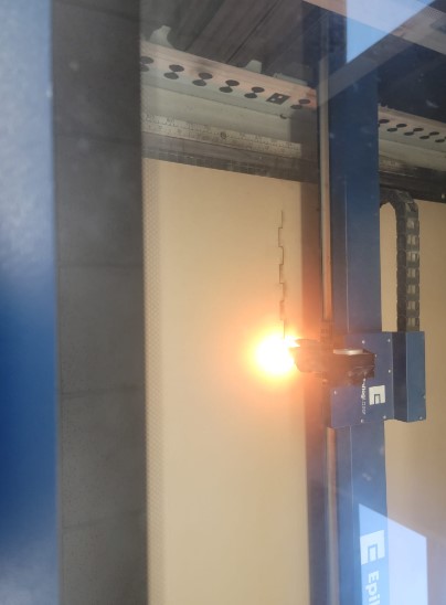
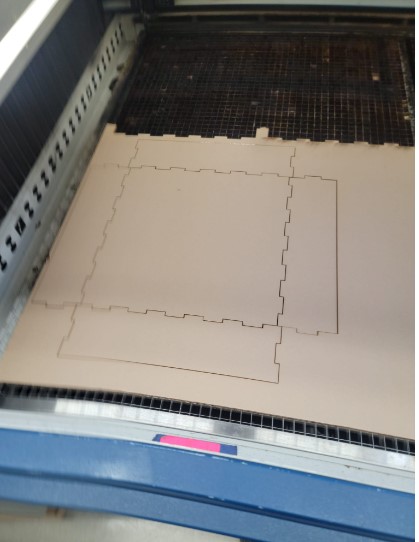
4 of the five panels cut fine on the left side but the right side of the laser did not cut through. I refocused the laser on the right side and ran the cut for the 5th panel with 3 passes. Discussing with the person in charge of maintaining the laser it seems like they were having a focus issue they were working through.
Once they were all cut the box fit nicely into the frame
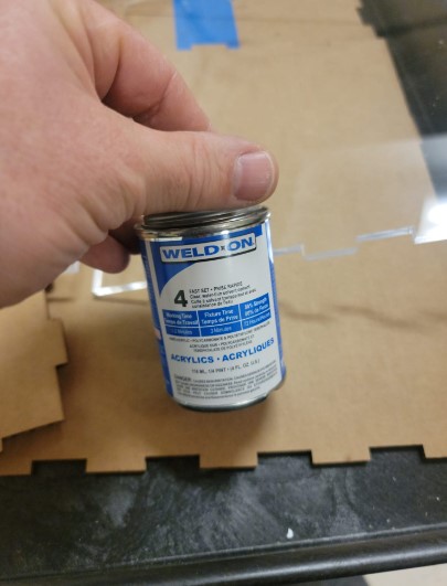
Now I needed to glue it together and so I used a plexiglass cement with the following data sheet
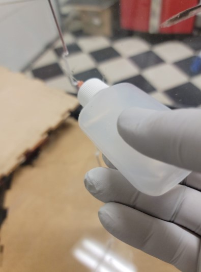
I only did used it in the garage with the car door open to ensure enough ventilation
This applicator was very useful
I used clamps to keep it together until the cement dried
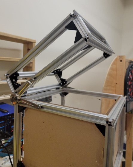
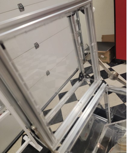
Box: Lid
The lid assemble was a smaller version of the box assembly with an addition of a hinge and a Door Lift Stay Support Hinge Damper
They were both easy to mount onto the TRails
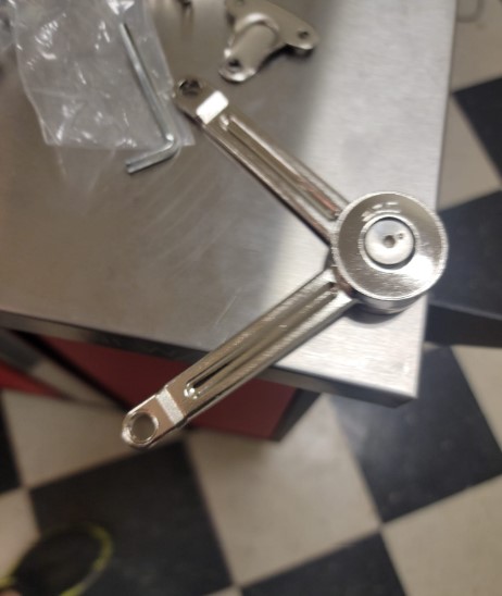
You can see the lid stay open
Now it is time to fabricate the internal plexiglass box including screw holes to mount the sprinkler head
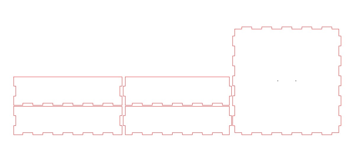
First I cut out the shape from cardboard to make sure it would fit
Looks good
Now cut the plexiglass
Clean cut
Use the clamps and cement.
I added holes to allow it to be secured to the T Rail
Here you can see the water pump mounted and another hole for the water tube to go into the lid
And here it is with the spinkler mounted.
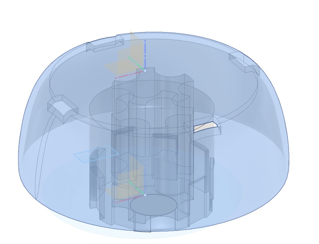
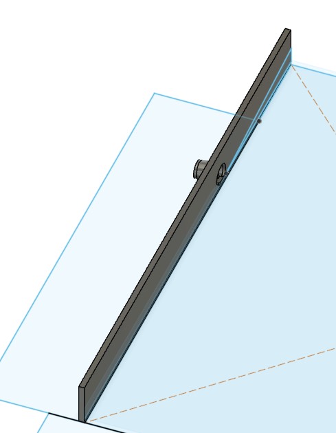
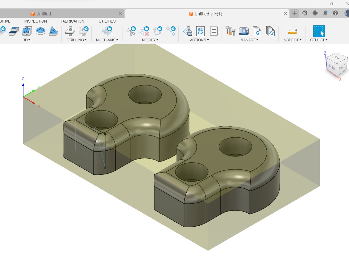
Box: Spinning plate
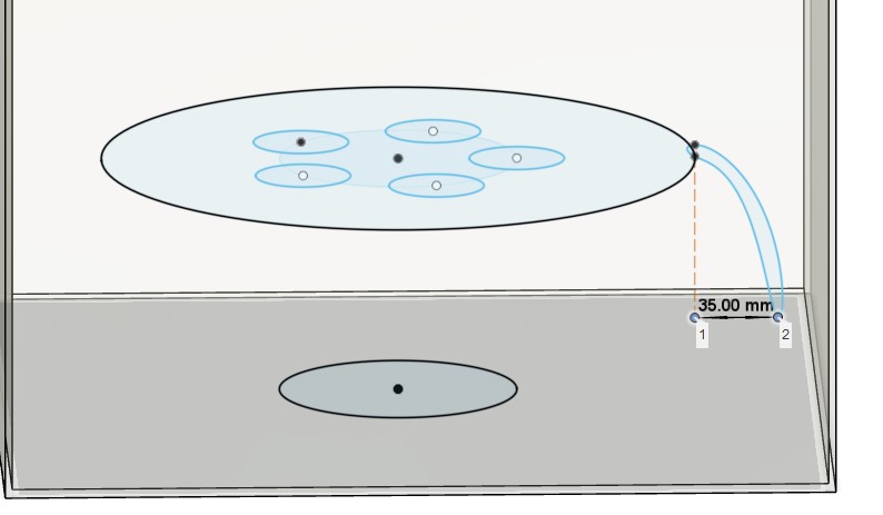
First I set up some user parameters I will use in sizing the spinning plate and it base
Now I made a round leg for the plate to sit on
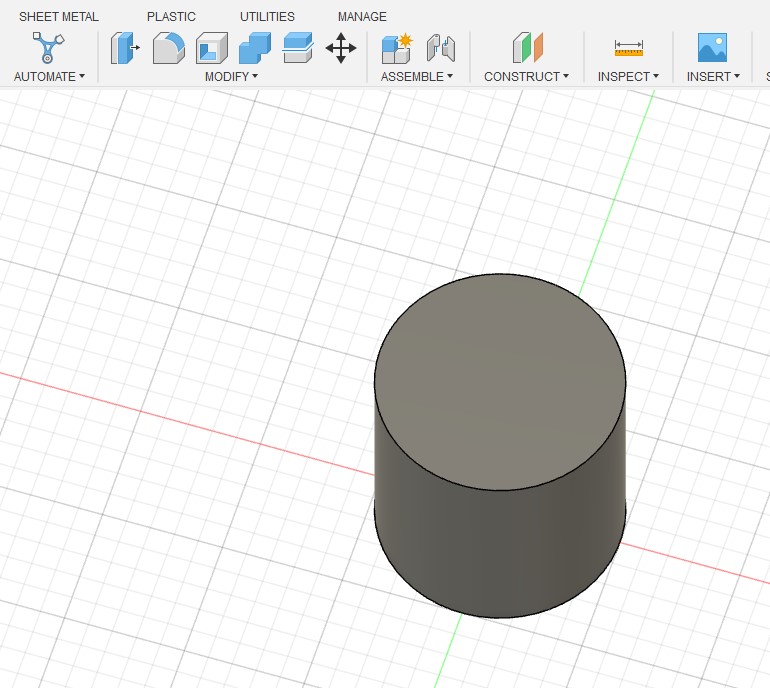
To create the shape of the base I will create a new sketch on the top of the base leg. I then create a circle and replicate it using the circular pattern tool followed but a cut.
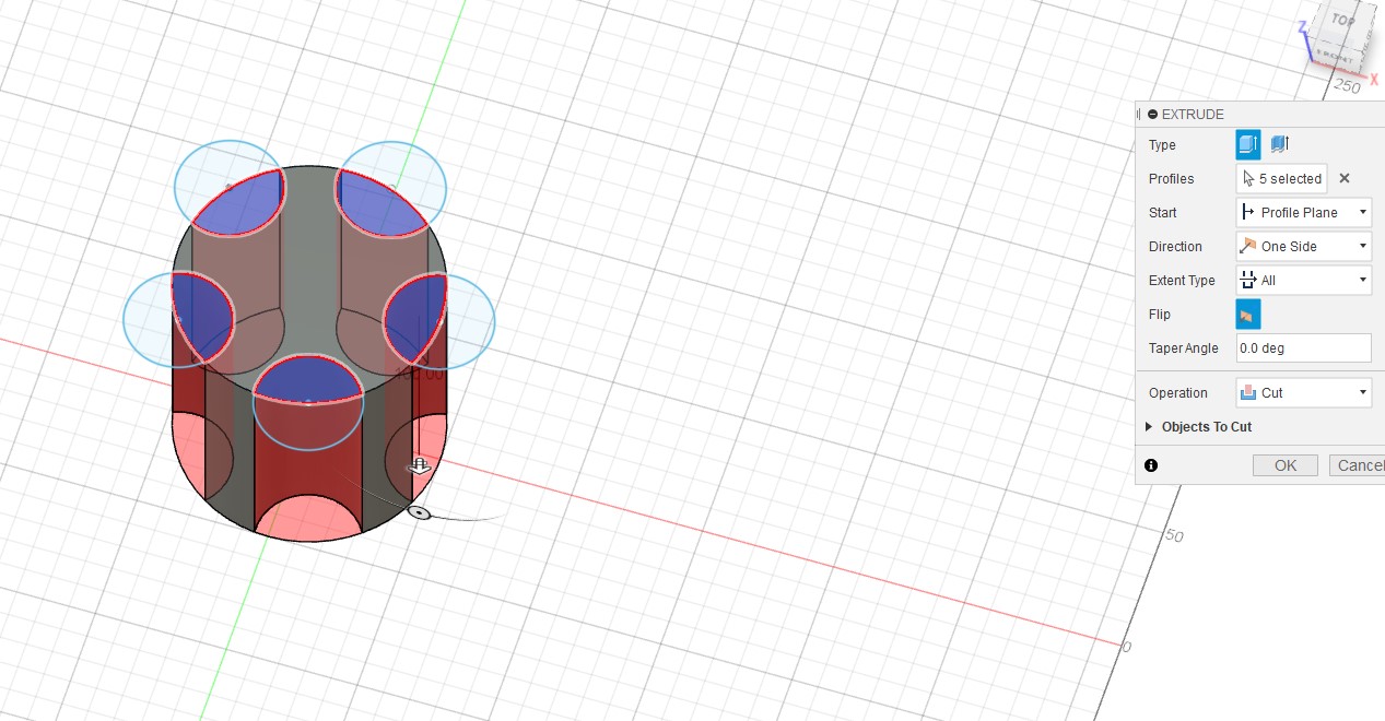
I then sketched on top again and created a circle to create the plate itself
Here I made a mistake as I did not select the whole plate and where the handy timeline tool come into play
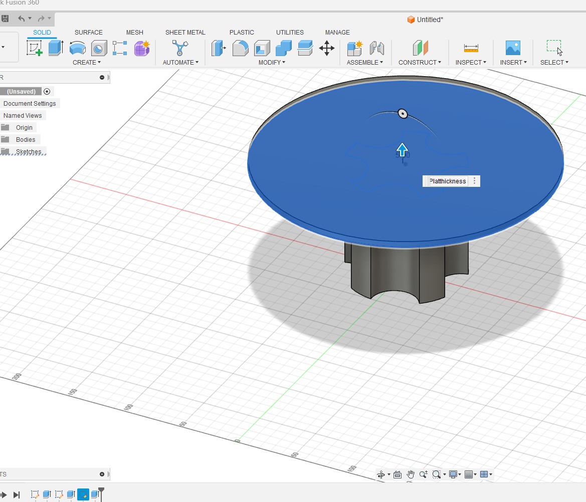
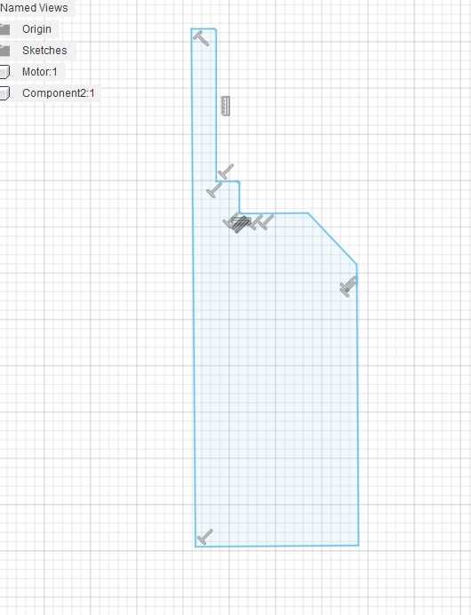
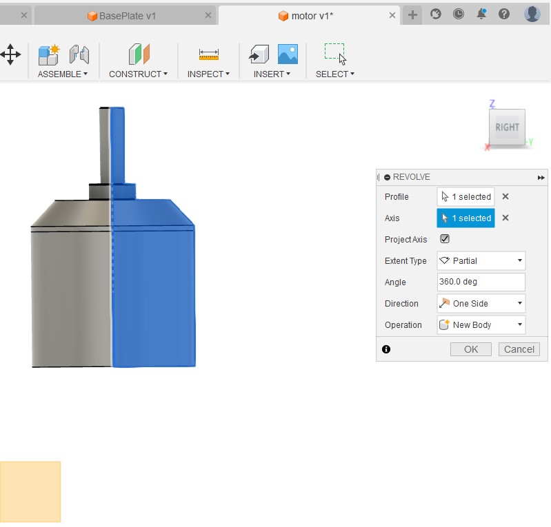
And we are back on track. I wanted to create a downward facing lip in order to provide some water protection for the spinning mechanism during the dry cycle.
To do this I am going to draw a sketch of the lip and have it rotate around the plate center axis
Start with sketch
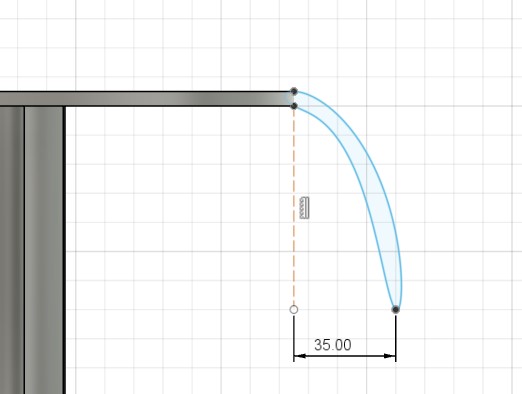
Then used the revolve to create the lip and set it to join the plate base.
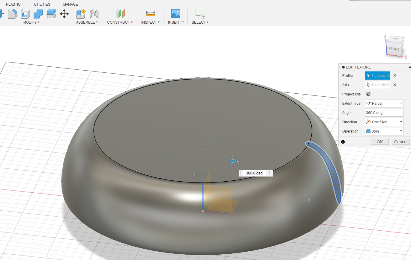
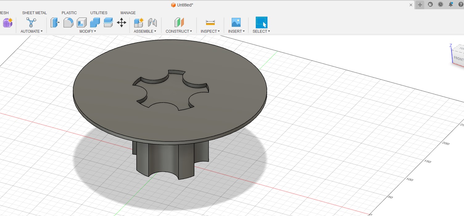
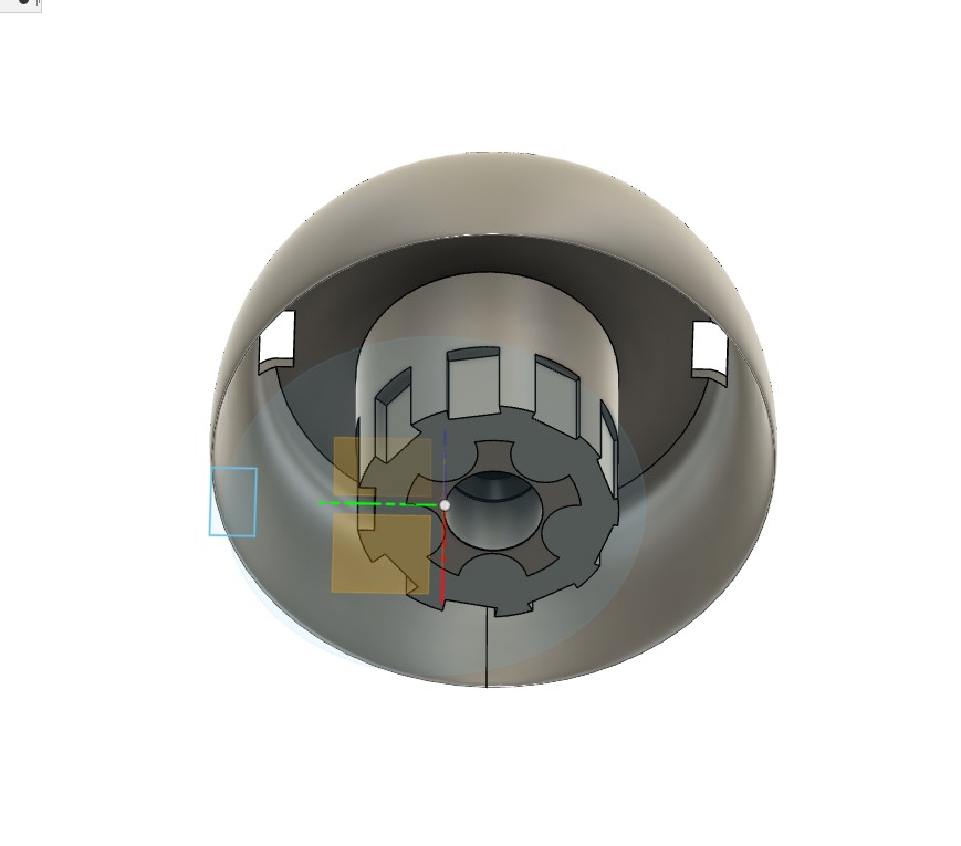
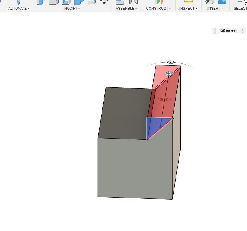
and there you go a first cut at the base plate
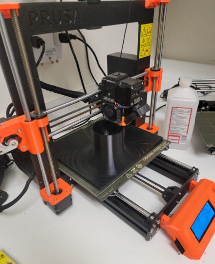
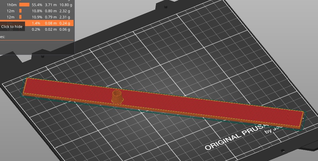
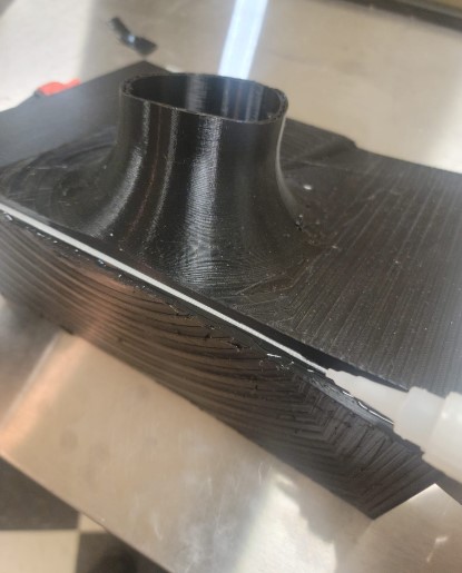
Box: 3D printing the plate
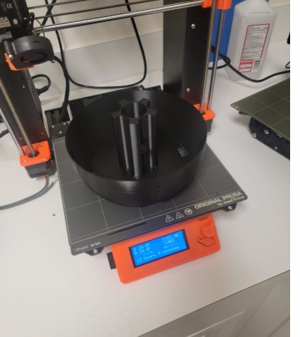
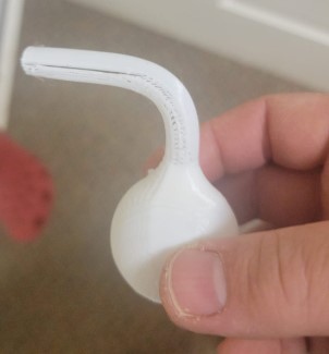
I started off by printing a test model aprox 50 of the size
After 5 hours, here it is:
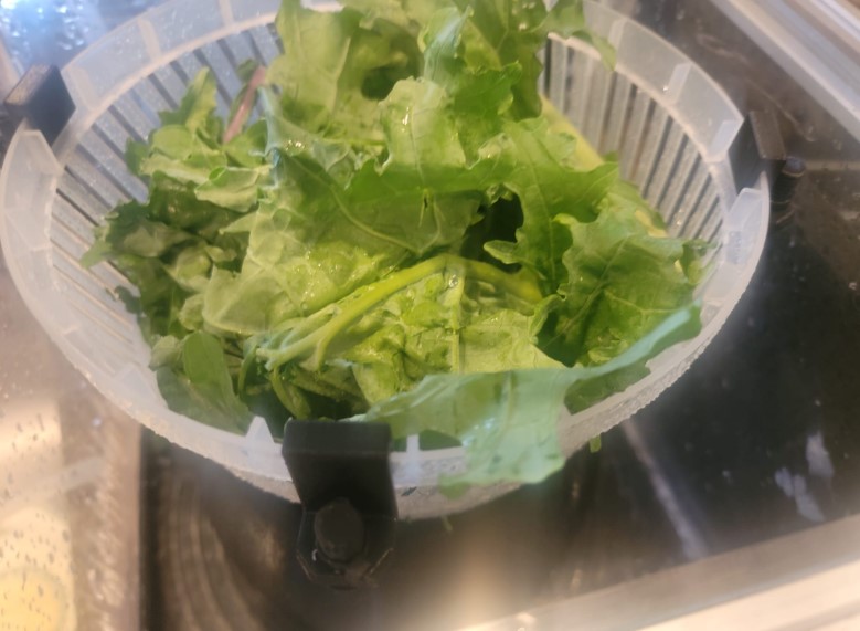
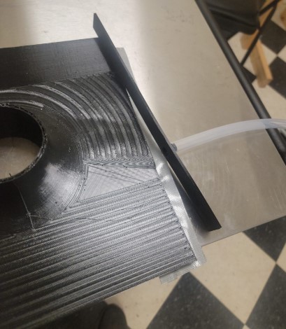
When I put it up to the salad spinner bowel I have it seemed to me that the overall size of the machine \ can be much smaller then I originaly planned.
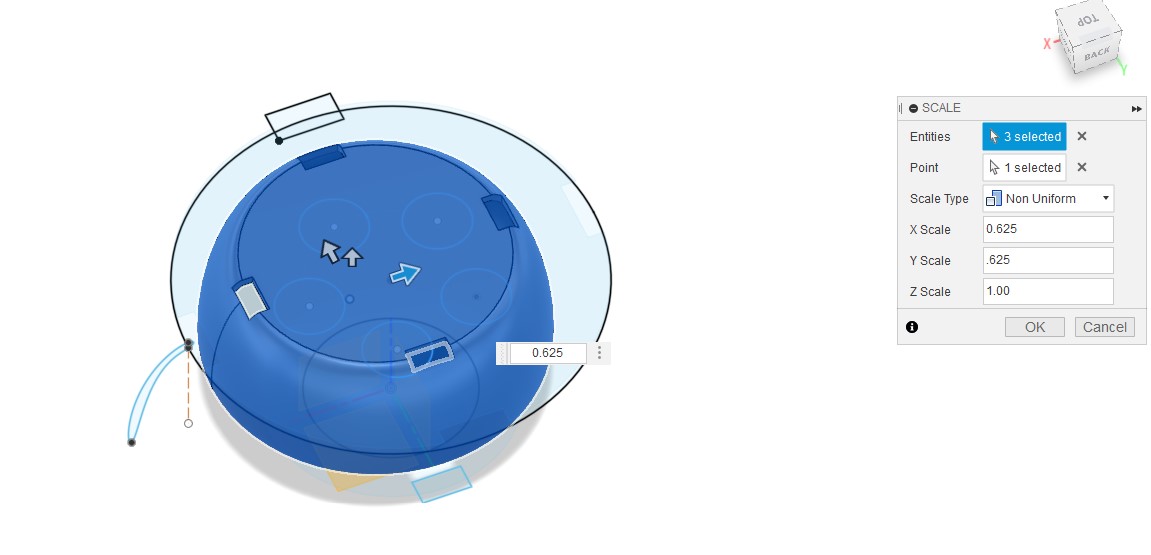
I think a good approach is the max the size of the plate I can print on the MK3S
The original size had a 320mm diameter but I am going to resize it to a 200mm diameter
I used the scale command leaving the Z as is and scaling the X and Y to 62.5% of the original
Here it is printed
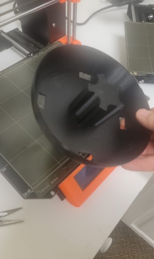
Now that I liked that size in order to make every thing work in fusion I had to go back and resize the plate in fusion to match.
Now we are ready to create the bowel holders
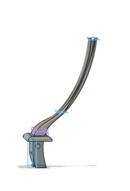
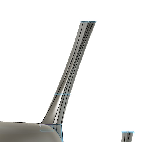
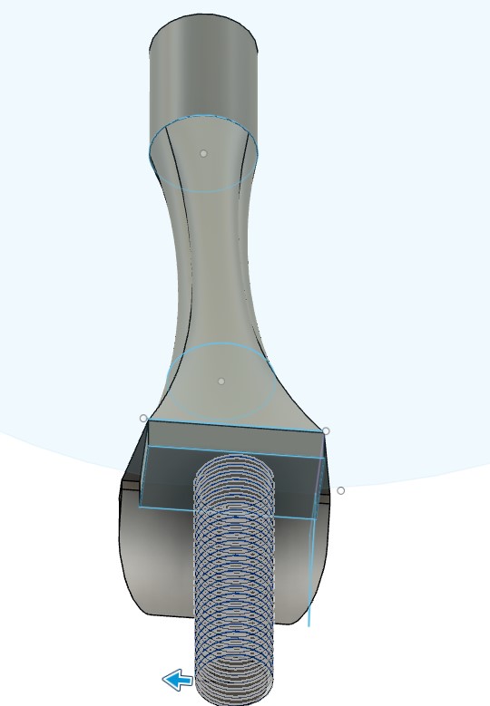
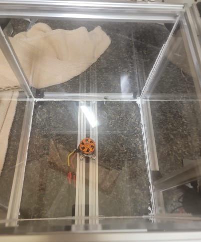
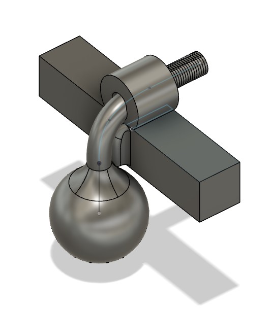
Box: Out runner motor mounting
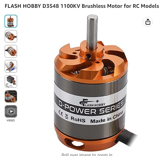
See below for discussion on the motor drive selection and decision to move to a direct drive mount on a outrunner motor. I am used a D3548.
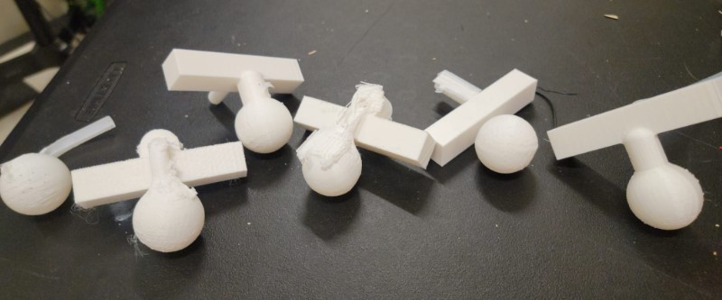
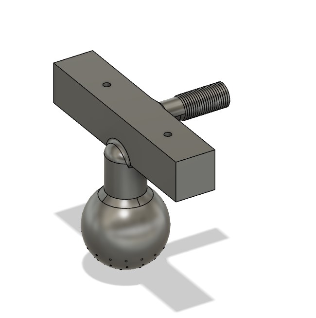
I found a model of the motor I am planning to use on GrabCad
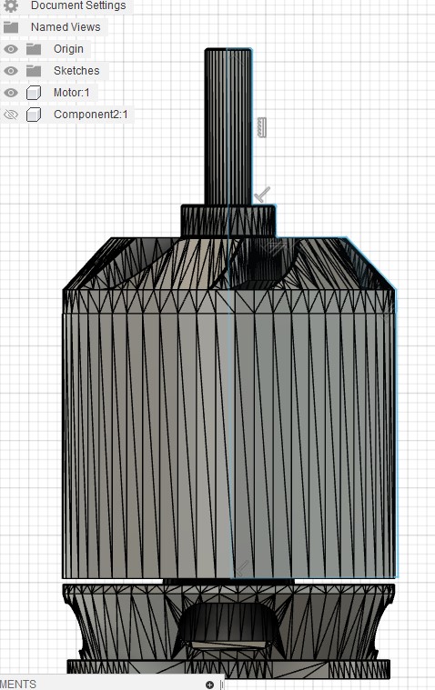
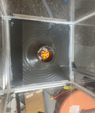
This an out runner and I would like to cut its shape into the bottom of the spinner to test a direct drive
As the CAD was made of many many pieces it was easier to create a similar shaped body. I traced the profile and used the revolved function to create an new body
s
Now I used the combined command to cut this out of the base of the plate for a direct mount
Creating a nice mount for the plate - i also think i do not need the spinner base any more.
I knew there was going to be a lot of stress on this when the plate spins so I filet everything I could to strength the joints.
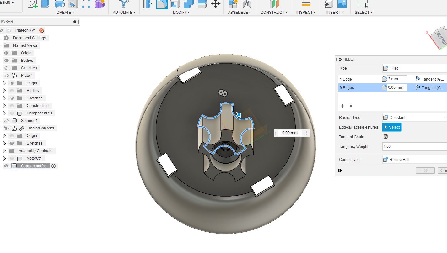
Got it ready to 3D print
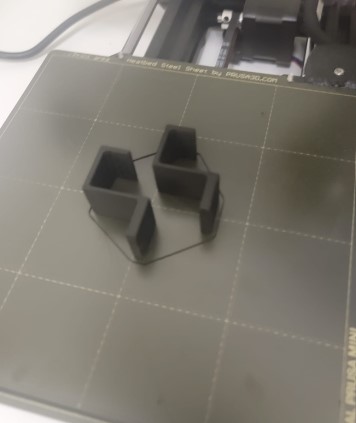
Box: Bowel holder
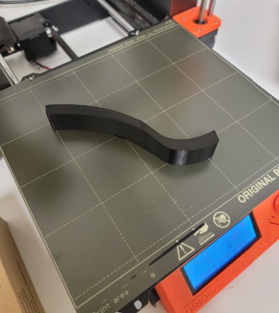
Initially I printed a basic arm to get a physical sense of the shape and size
After have a basic shape in the early design I needed to have a pieces that was help in place on the plate.
I started by adding a wedge at the plate level and tweaking the shape but it was very unstable
I decided to use to features to do that.
1) Redesign the base to snugly fit on the shape of the plate
2) Create a threaded rod on the bottom and print a nut that will hold the are in place
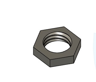
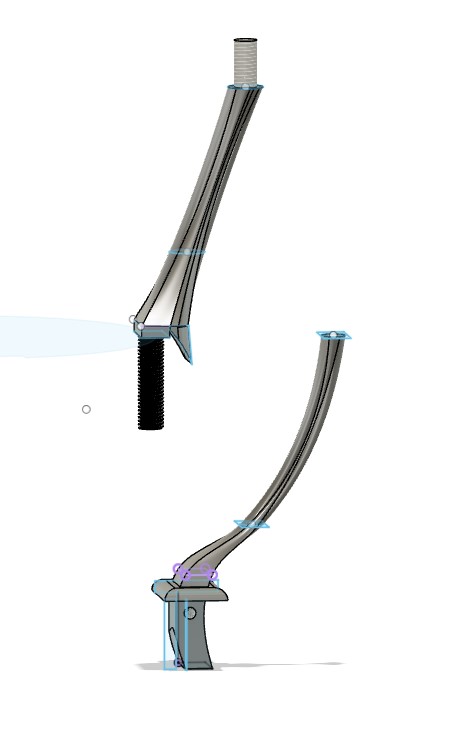
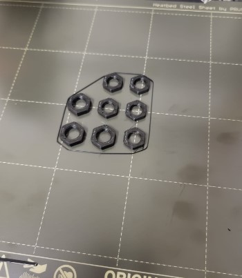
Here is it assembled
and now to test
When discussing my progress with my local instructure Dr. Fagan, the feedback I got is the need to have a screw to hold the plate to the motor shaft
I decided to put in a pocket to hold the bolt
Then a screw hole all the way to motor shaft
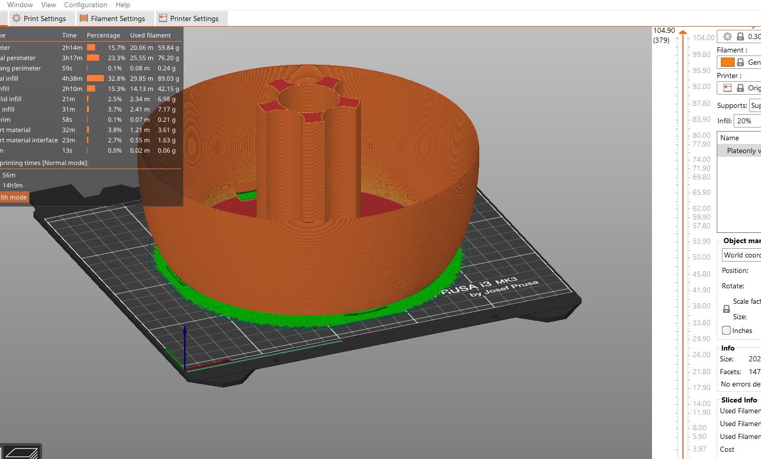
Once the design looked goo it is time to reprint the plate.
After 13 hours we have a new plate
And the screw fit with the bolt holding it in place.
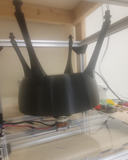
Box: Bowel hooks
To ensure the spinner bowel does not fly out I need to add a hooks that will connect to the top of the plate arms and hols the bowel in place
I decided to go with a simple 3D printed design
Got them 3D printed
And istalled
After some testing i found out that the hooks allowed the bowel to have too much motion that got out of hand when the RPM went up.
So I redesign the hooks to have a tighter fit with the bowel.
I also replaced the bolt with zip ties as the bolts came loose over time. These 2 changes got the bowel in with a tight fit that works well.
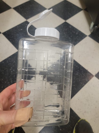
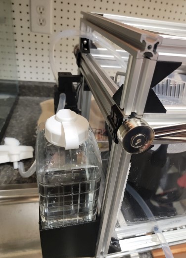
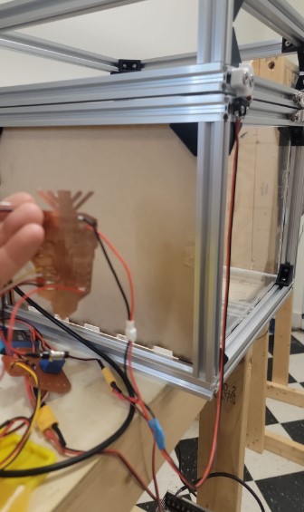
Box: Water reservoir
I had decided to use a square water container as the water reservoir
I wanted to build a holder that will attached ot the back of the frame and hold the water bottle
I added strong support to try and only connect it on the bottom rail
And we are ready to print
Looks like a good fit
3 M5 screws secure the holder to the frame
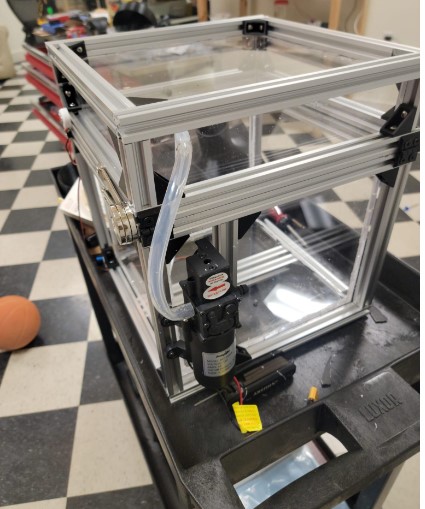
And here it is mounted and full of water
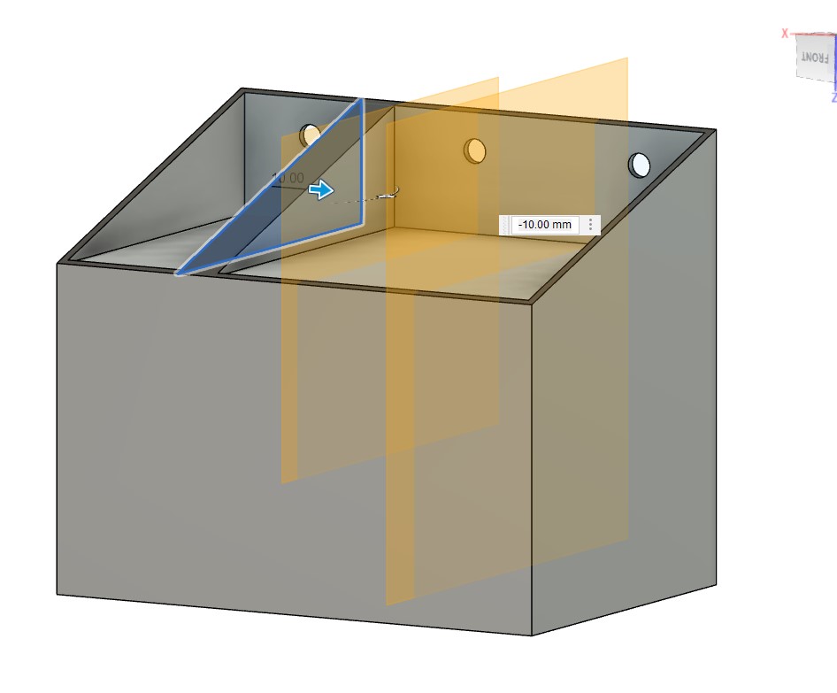
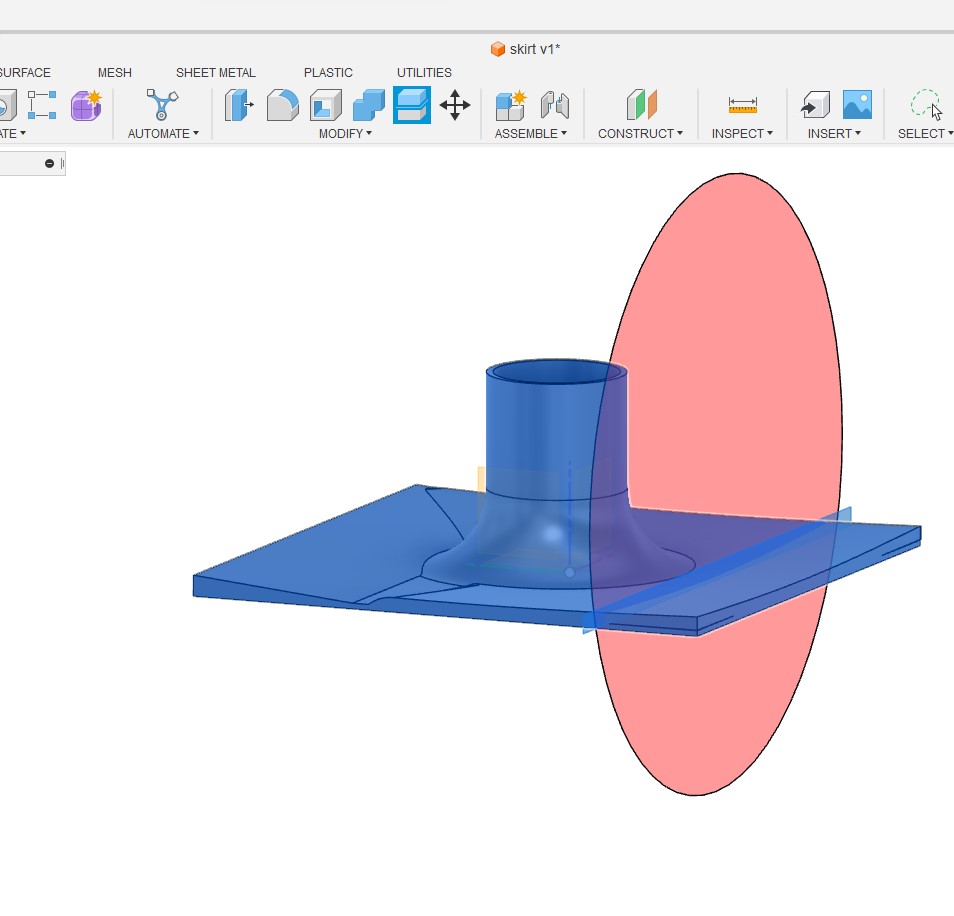
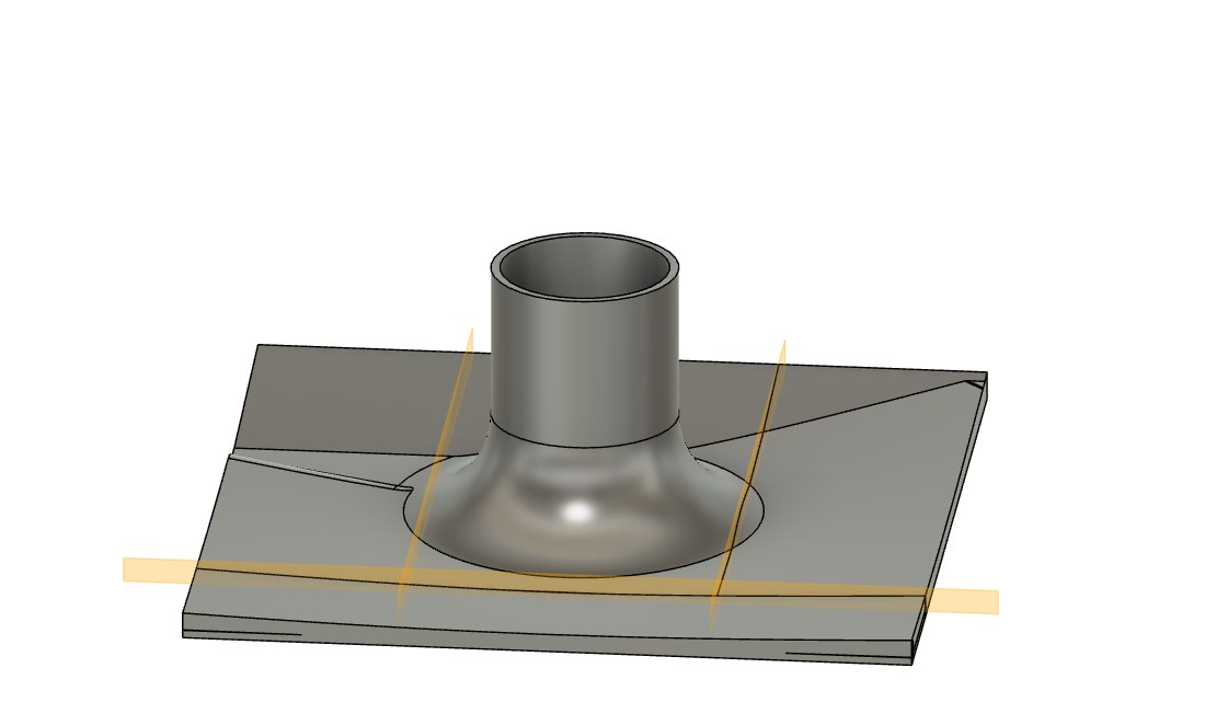
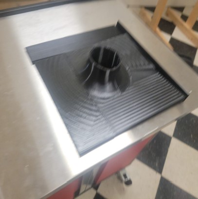
Box: Water skirt and drainage
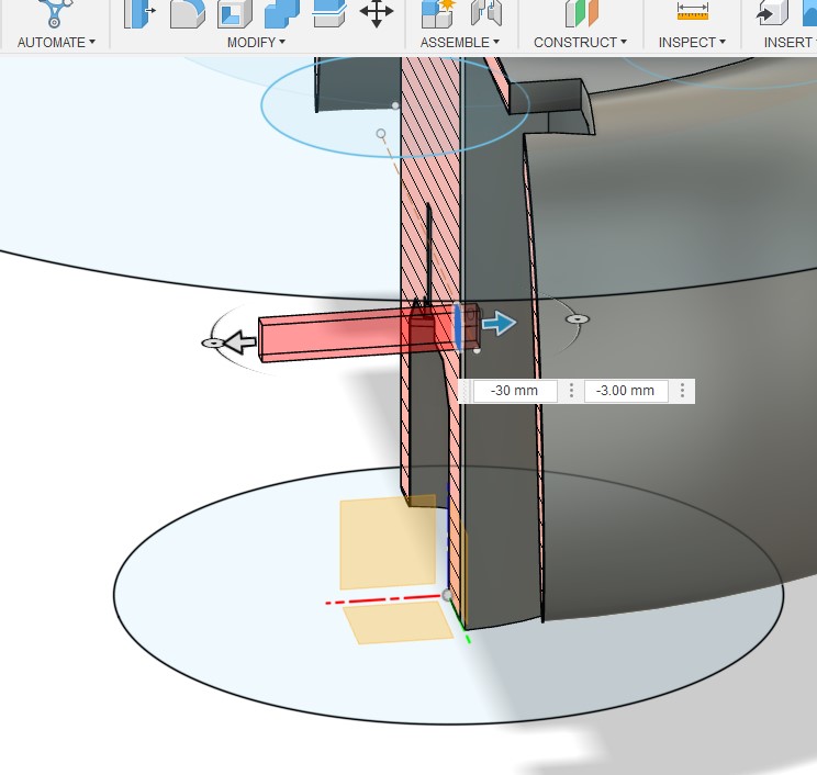
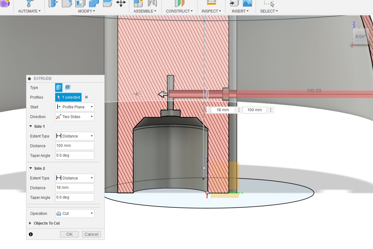
My plan for water profing the motor and providing a gravity based drainage is to create a sloped rubber base for box with a rasied skirt.
The skirt will go between the motor and the plate lip thus stopping any water for getting into the motor.
I started with a fusion design
Added the drainage slopes
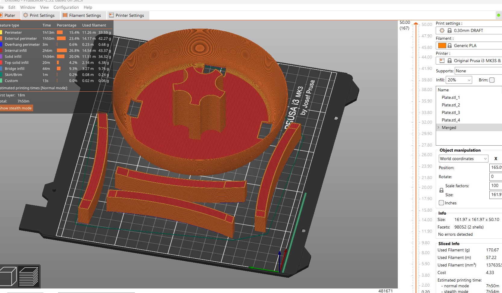
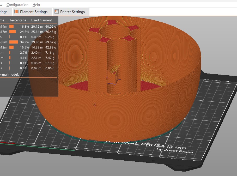
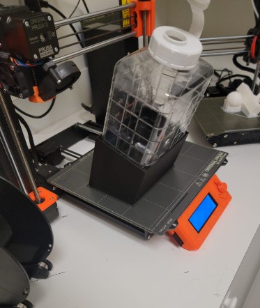
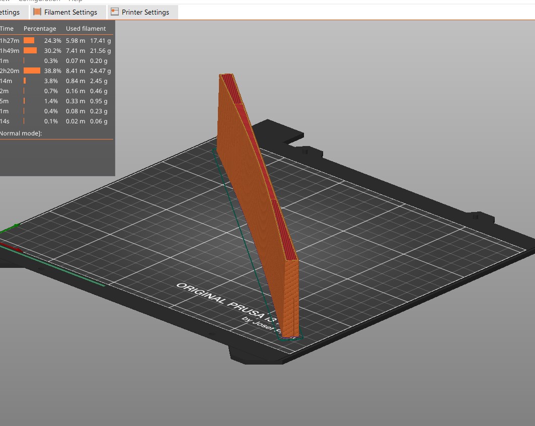
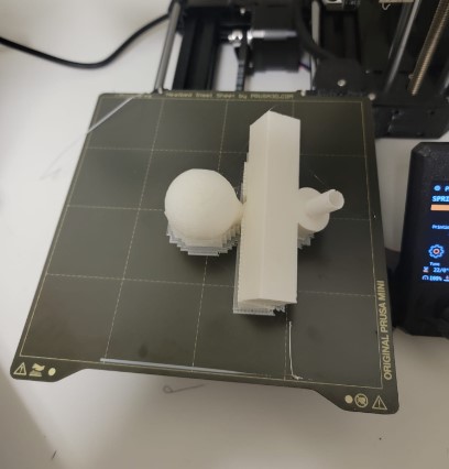
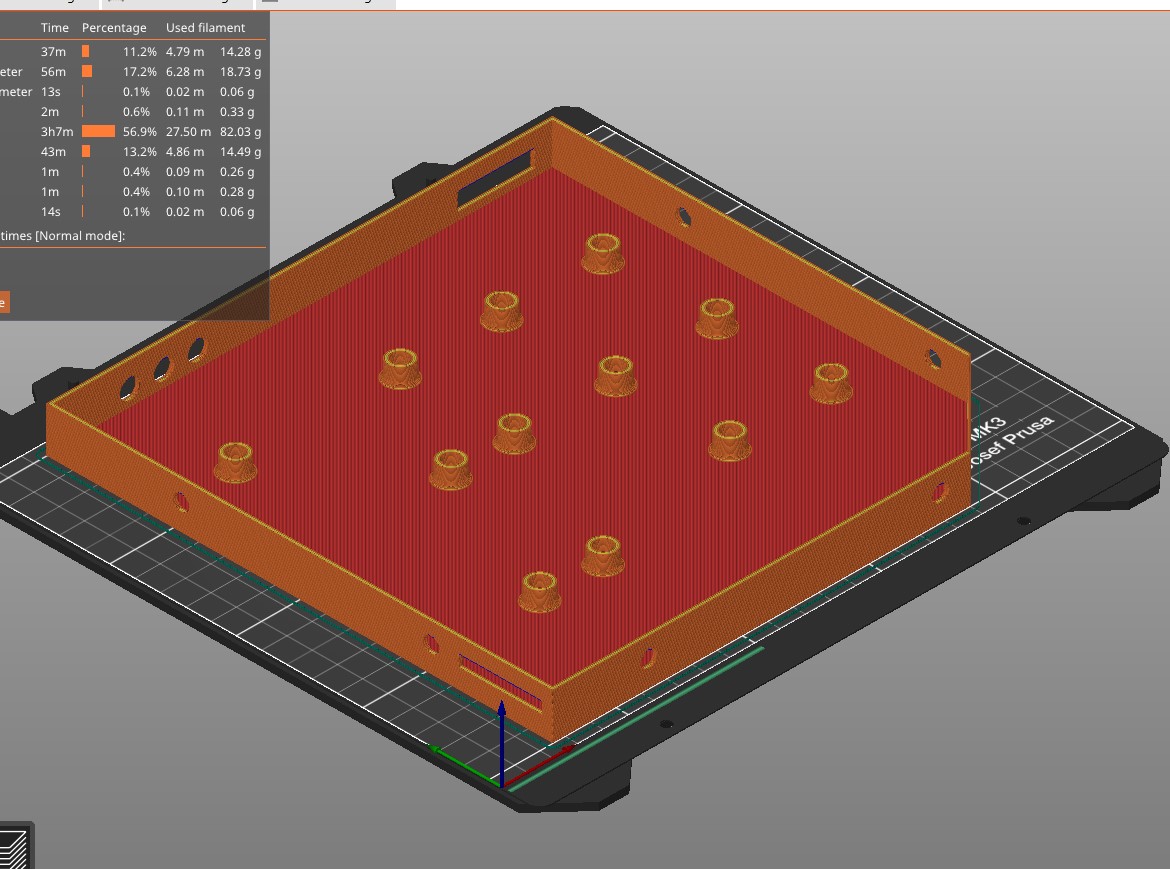
Unfortunately my Prusa is too small to print the whole things at one so I had to cut it to be printed in parts
Printing in TPU is slow if you do not want stringing It is a 23 hour print !!
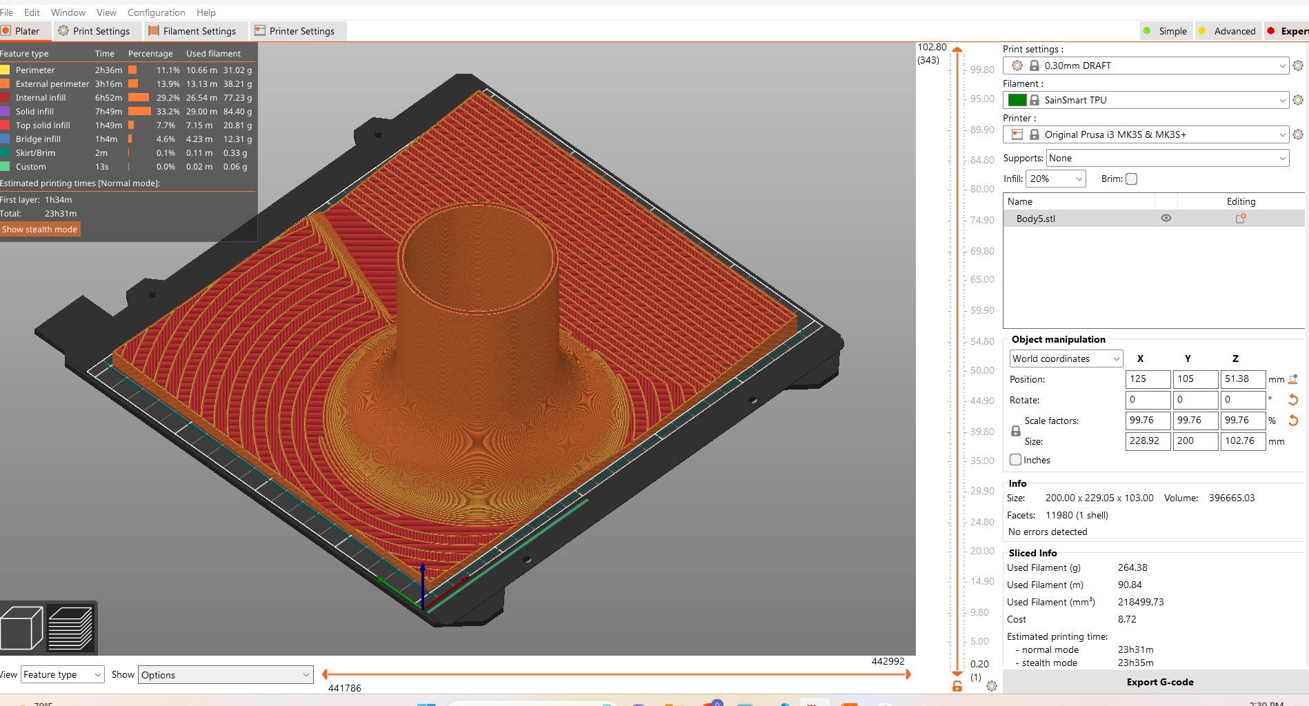
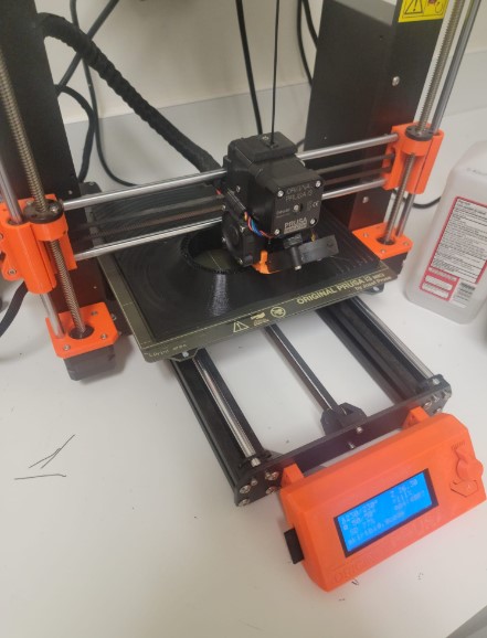
Here it is in progress
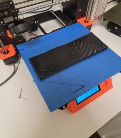
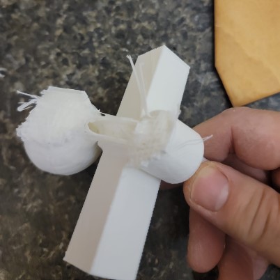
Fully printed
Printing went well but remove the print from the plate was nearly impossible and ended up destrying the plate.
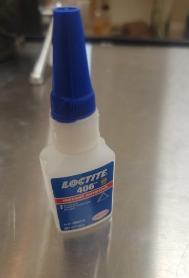
This did not happen to me in smaller prints I did but after going back and reviewing the Prusa materials guide as well as reading some user form it seems that I missed the need to either 1) Add a layer of glue stick 2) Put down blue tape the print on
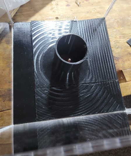
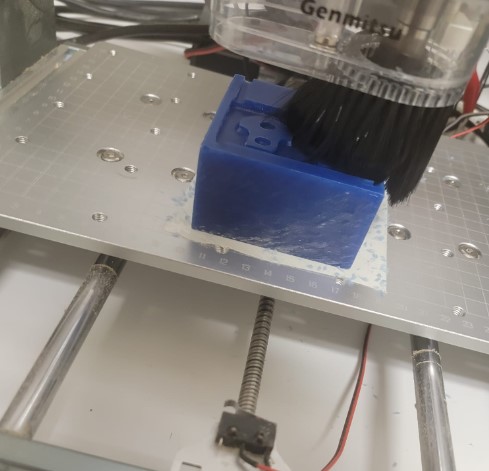
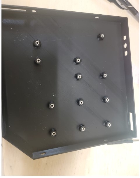
Now I have all the parts printed time to check fit in the box
After reivew it seems that Loctite 406 is a recommended glu for TPU so that is what I am going to use to turn these 3 parts into 1. But before I do that I can see 2 things that I need to add and adjust:
-
Add a drain connection
-
Expand the neck to fit the screw that I added to the plate
I created a drain connection / edge
Ready to print
Here it is

I also cut the next of the skirt to fit the new screw placemen.
I needed to connect the different parts of the bottom into one
Some reaserch showed that for TPU loctite 406 is a good option.
I used ducktape on the bottom hold the pieces together until the glue dried
after some more tests that drain was working well.
The drain worked well but i still got a lot of water under the TPU base from all the side.
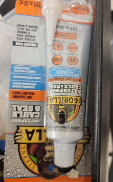
I decided to use some clear silicon to waterproof the edges and funnel all the water into the drain
And we are ready to go
Unfortunately over the next 2 days the caulk did not cure and was a mess. I ended up taking off the base, cleaning out as much of the caulk as I could and resealing it with silicon which cured much better.
Box: Feet
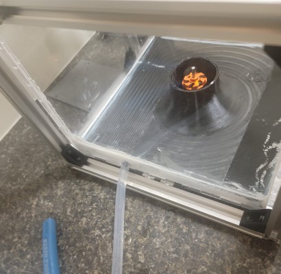
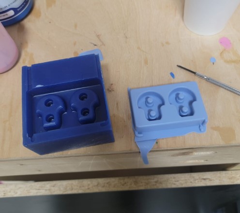
I used molding and casting to make mushroom shaped feet for the machine.
Here you can see the design
Milled out of wax
Running a roughing pass followed by finishing pass
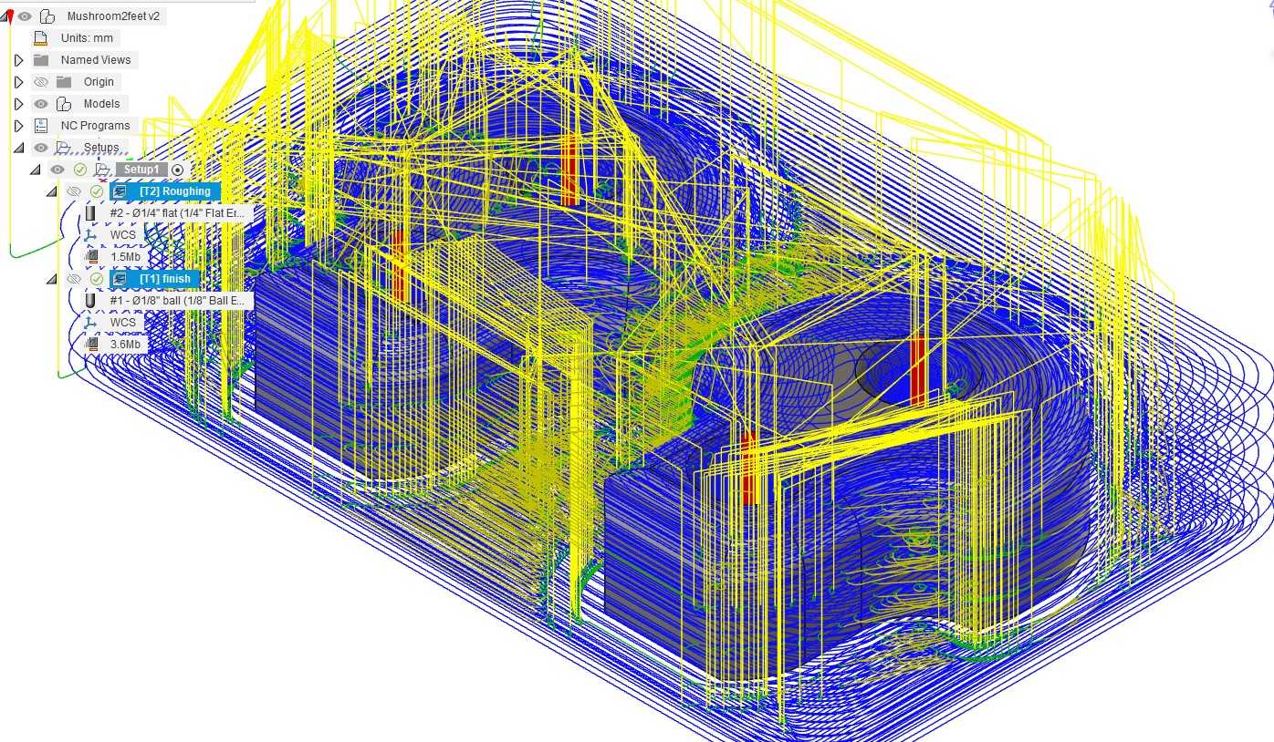
Cast a rubber mold
Plastic legs ready to go
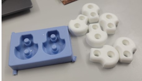
And here they are mounted
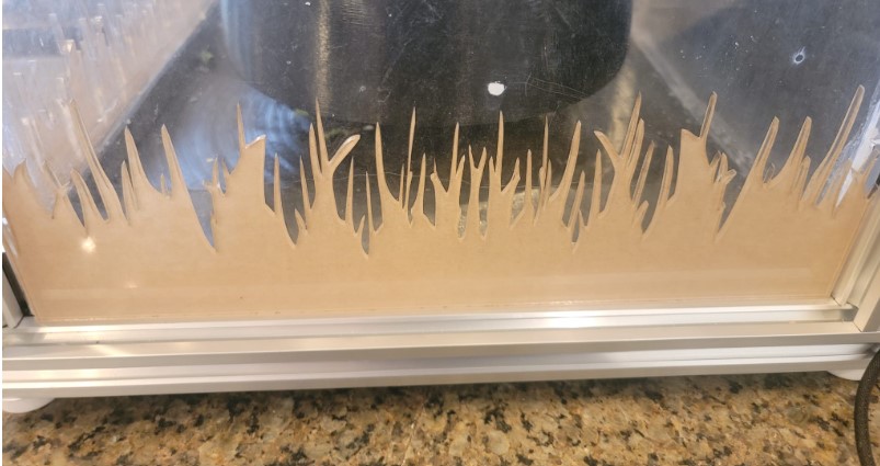
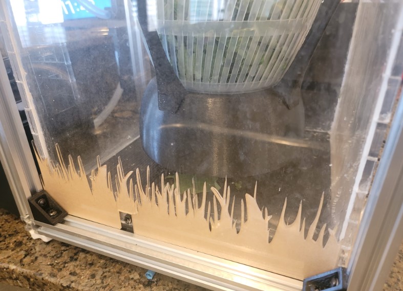
Box: Decorative design
To help hide the silicon on the bottom of the box I found a garden silhouette.

For the side I added a square cut out for the drain

I then cut it out of 1/8 inch plexiglass
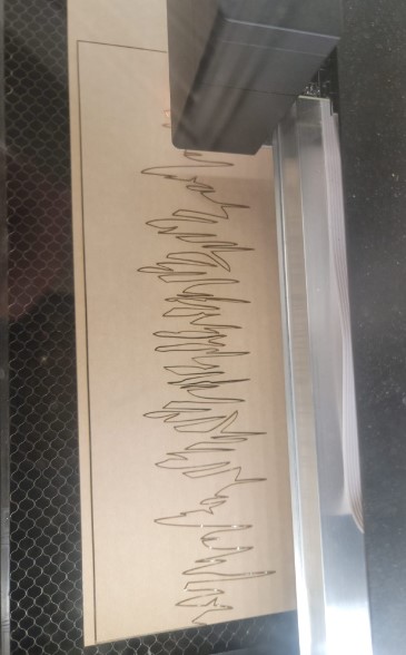
and then I mounted them which worked out well
Here is the front
and the side
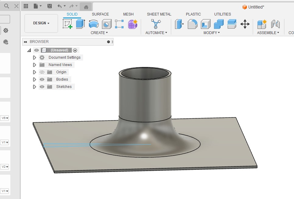
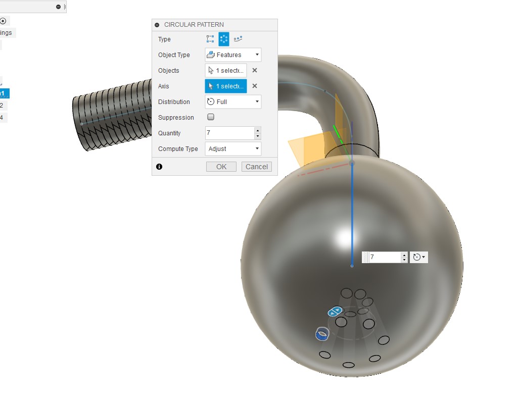
Box: Sprinkler head
The machine needs a spinkler head and so started up fusion. It will be secured to the LID from the inside and will be feed by the 3/8 hose coming in from the pump.
I used a sphear with a pattern of holes
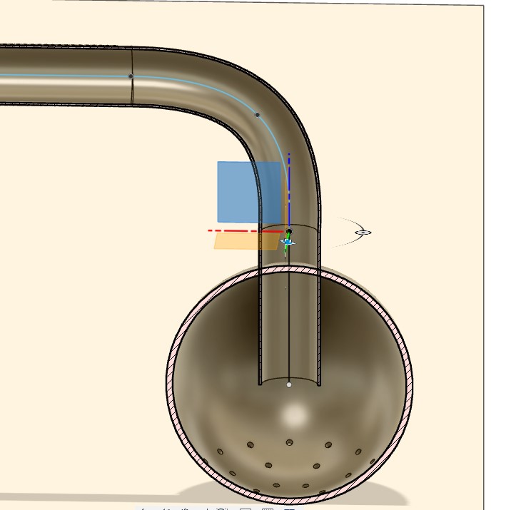
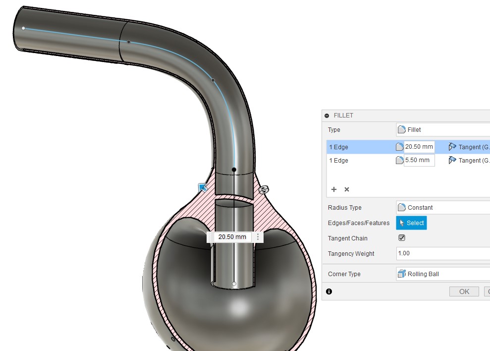
Used fillet to fortify the connection
I ensured the water flow path was open
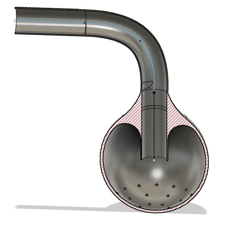
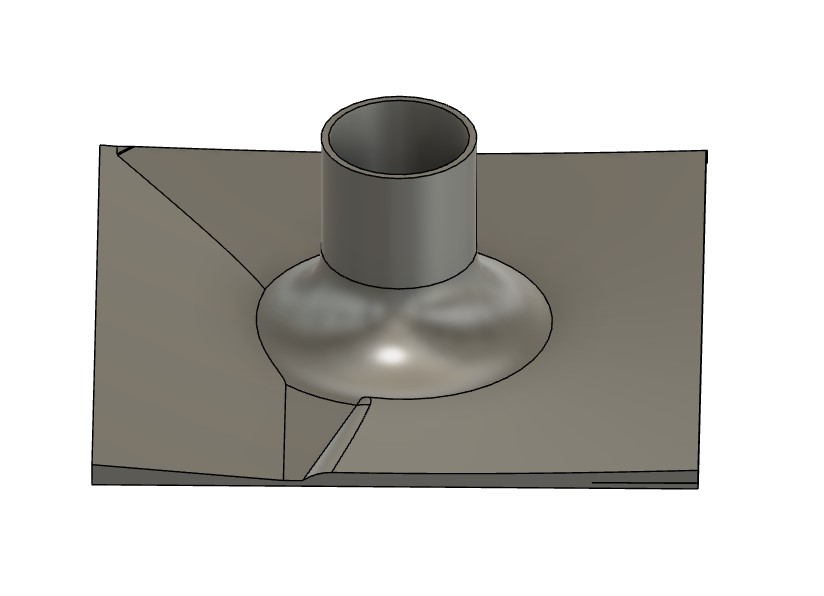
I ended up making the walls too thin and so it was very brittle during the print
I added more fortification and a square peg on each side I will use to mount into the lid
Print went well
But agian as I remove the support it was very brittle
I went through a number of priting settings to try and get this working as consistently the incoming connection kept have water leaking.
I fortified the design, moved the square overhand to cover the bend of the pipe and reduced the printing layers to 0.15mm. I also added 2 screw holes to mount onto lid.
And here is the final version
Motor: Spinning Motor set up
For my vegetable washing machine I initially purchased 3 parts:
-
12-24V power supply
-
12-24V / 80W DC Motor
-
12-24V Motor ESC
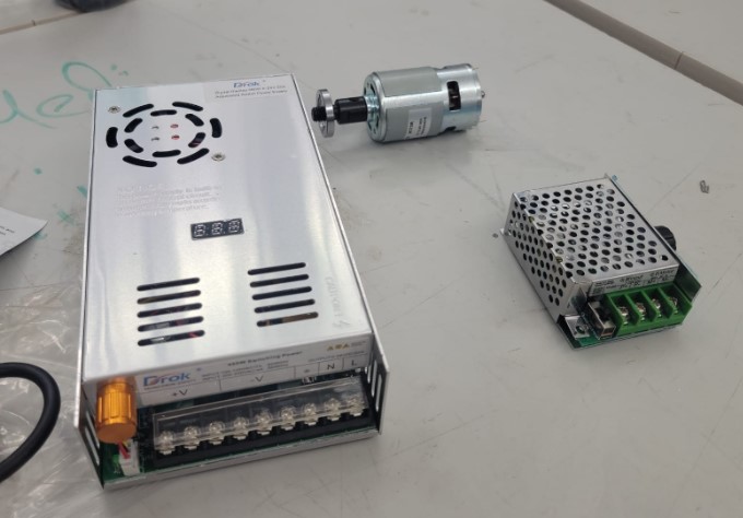
The ESC is controlled by a Potentiometer and once I got them connected they all worked well together. When I turned the knob the motor speed changed.
I want to be able to control the ESC with the microcontroller so I can adjust the speed for the wash and dry cycles.
First I need to understand how the Potentiometer works with the ESC. There is a plug with power and ground on either side the middle wire voltage change based on the potentiometer position ranging from 0.5V to 3.6V.
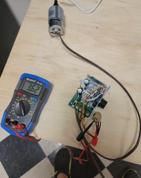
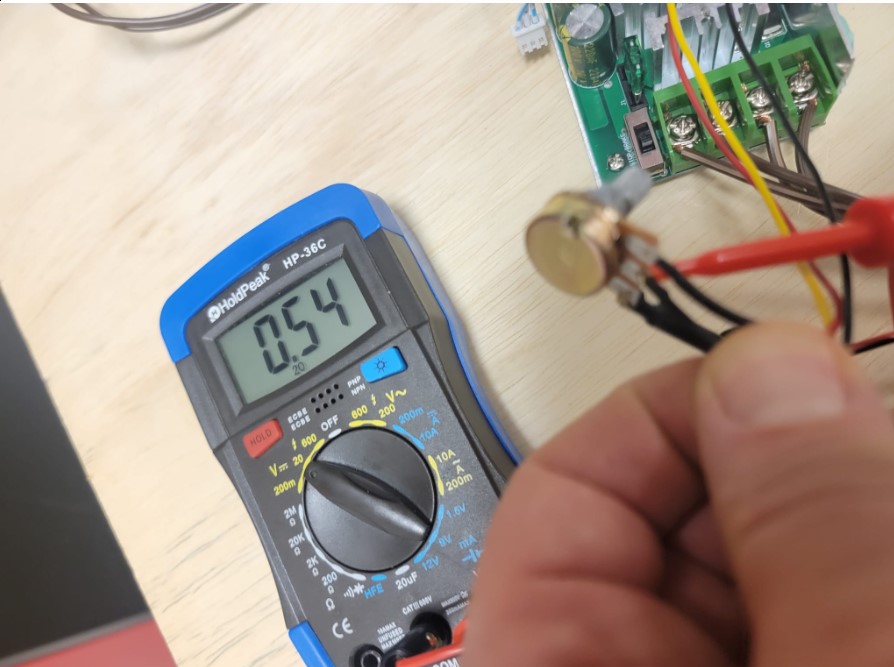
I was not sure how to approach this, my initial plan was to use 2 resistors and some relays to switch between 2 speeds. After reviewing Dr. Gershenfeld class and reflecting on the transistor discussion I came up with the idea of used a transistor to replace the potentiometer and a capacitor to smooth out the control signal from the microcontroller.
I ran this by our local instructor Mr. Dubick and my classmate Adam Durrett that have strong electronics background and they agreed it should work!!!
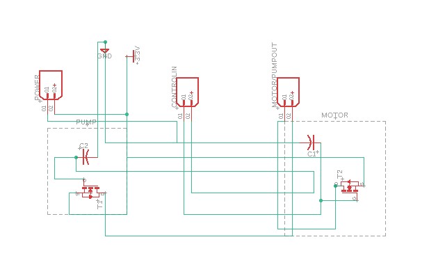
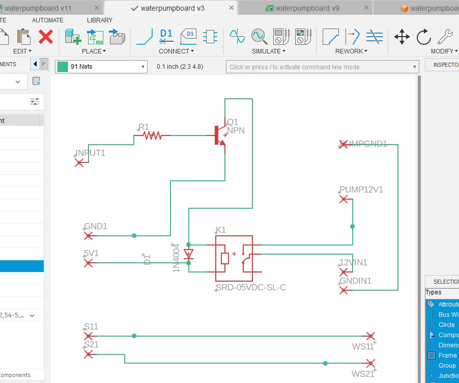
Motor: control circuit design
I decided the set up the board to control both the motor the spin the Vesgtable Basket as well as the Water pump even though my focus this week was on the motor.
For each I would have a control signal come in from the micro controller on the main board. I would change the frequency of the signal the change the speed, putting a capacitor on the line would smooth it and would replace the line in with the potentiometer.
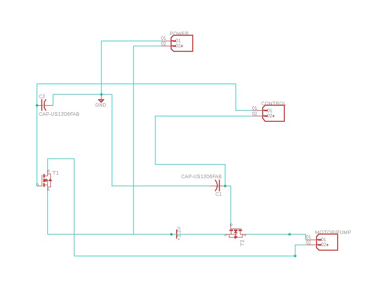
Not to get things a bit more organized. It is a relatively simple circuit
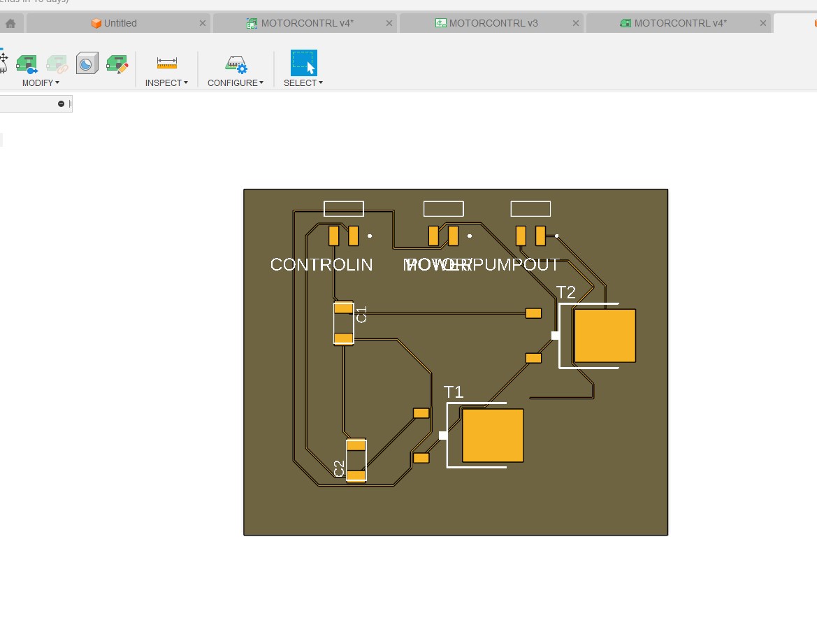
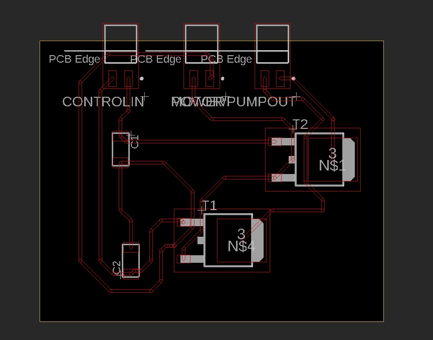
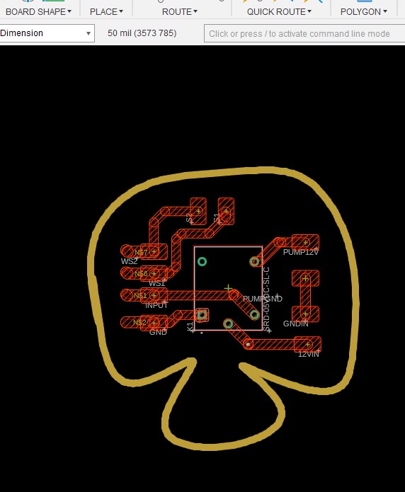
Not pushed it to the 2B Board and started tracing
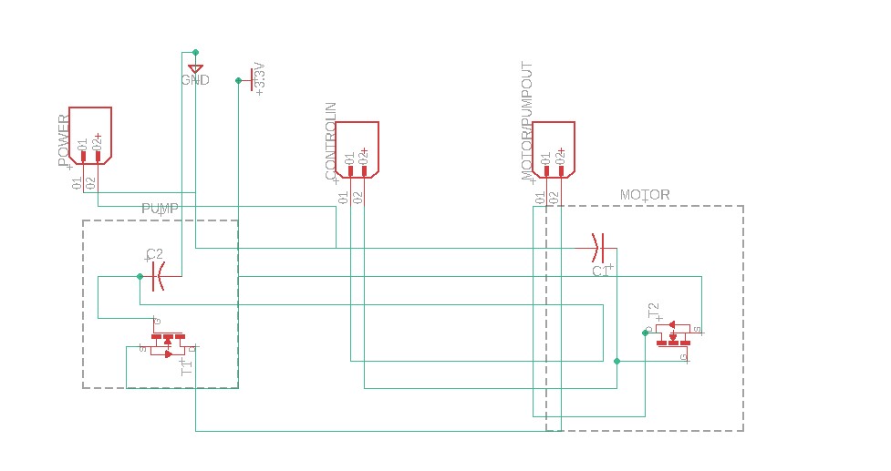
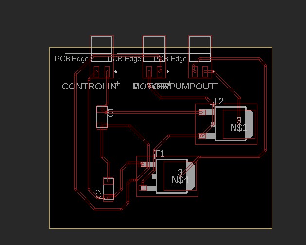
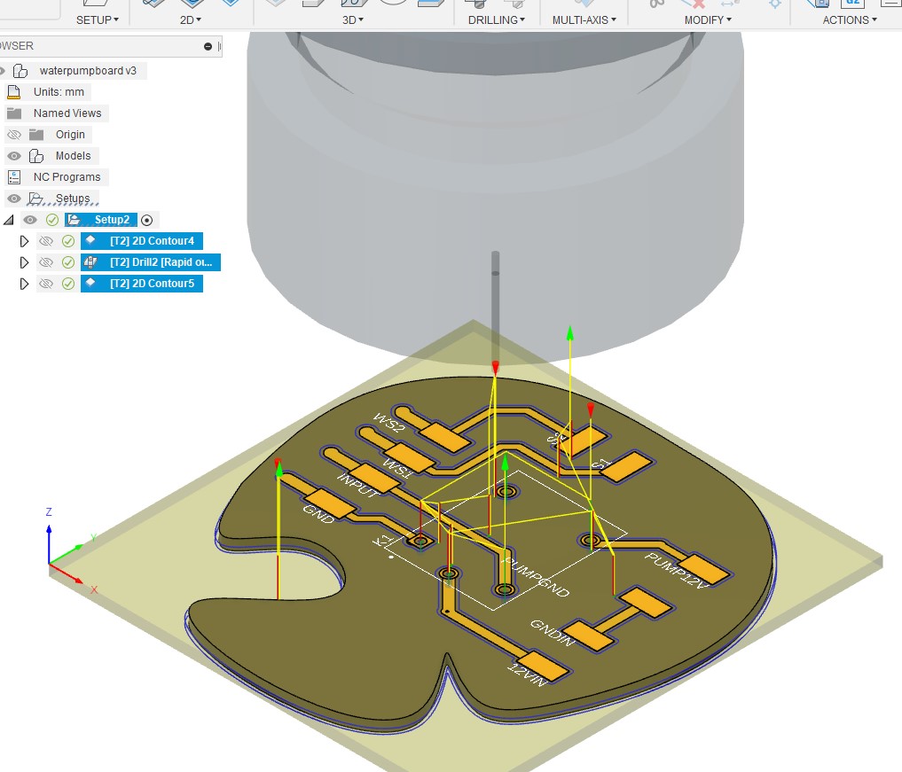
Motor: control PCB design
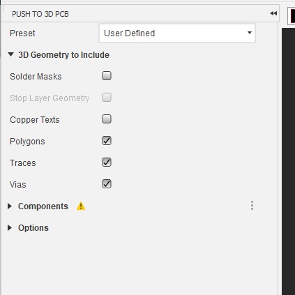
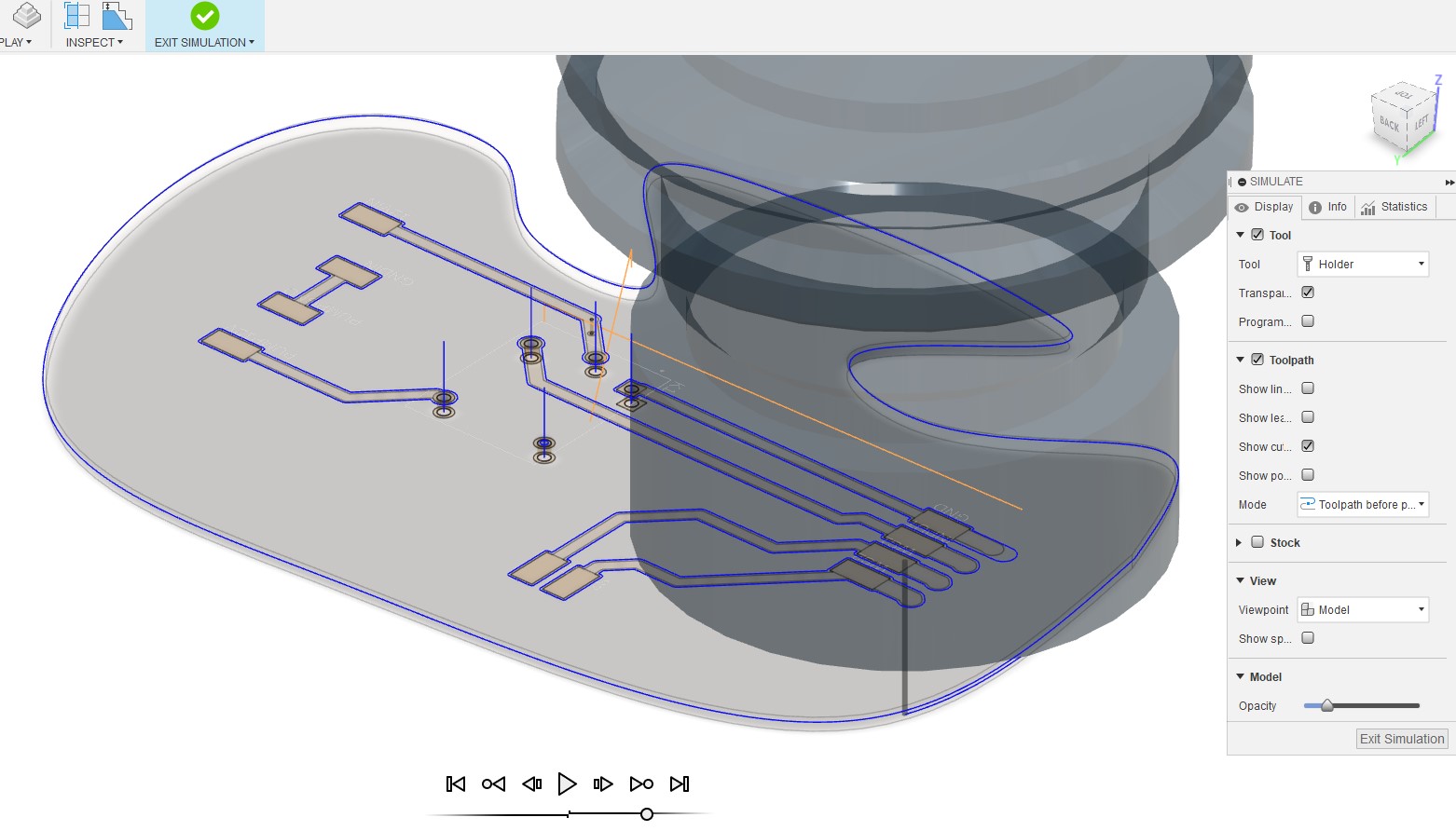
Pushed to the 3D board get ready to mill
When I reviewing the milling it was very tight due to the tracing.
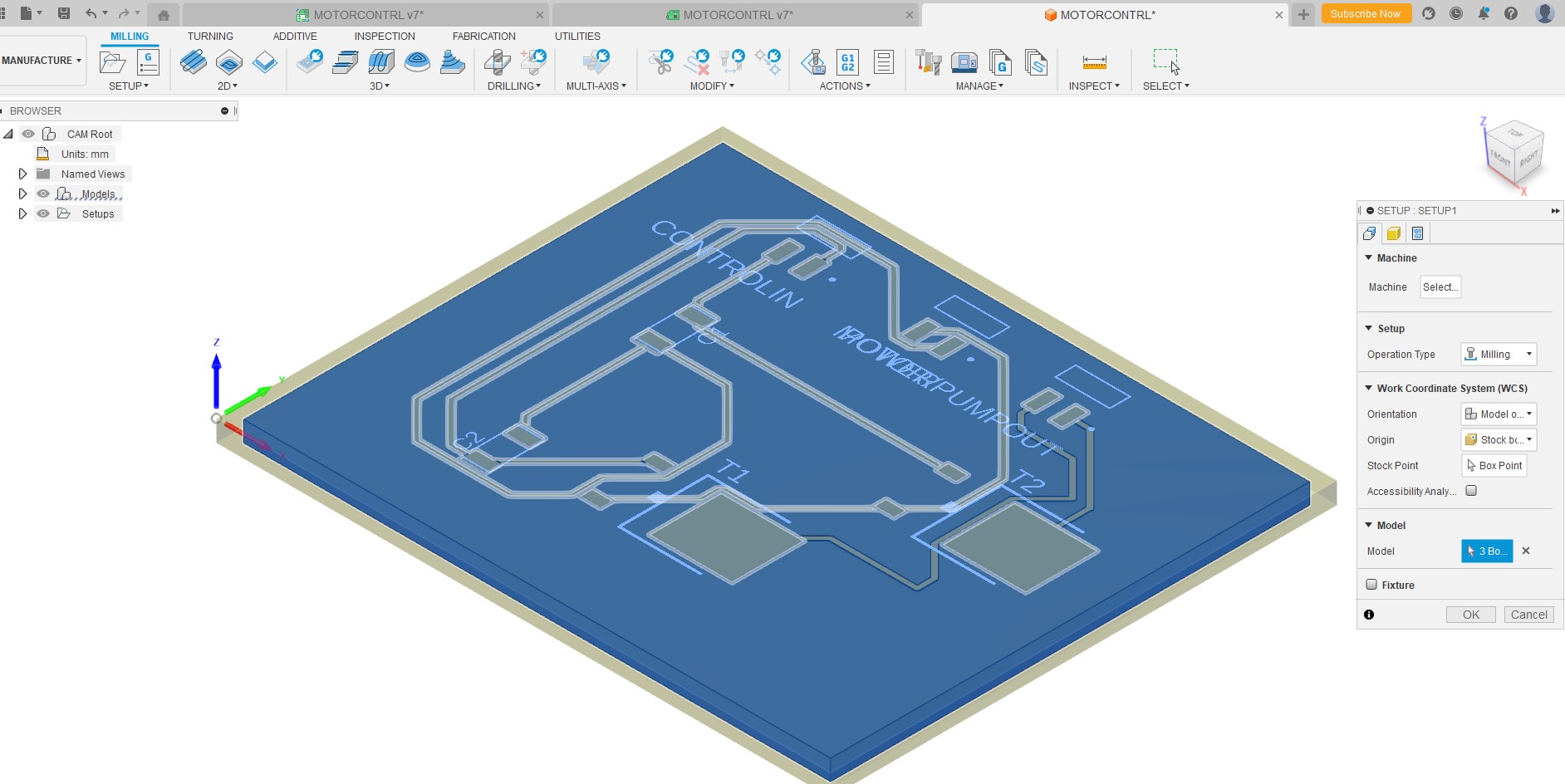
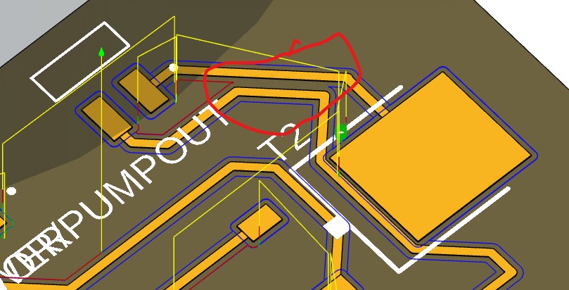
I reviewed the connectors and saw that by switch a few things around I could simplify the tracing and provide more space between traces to make for easier milling
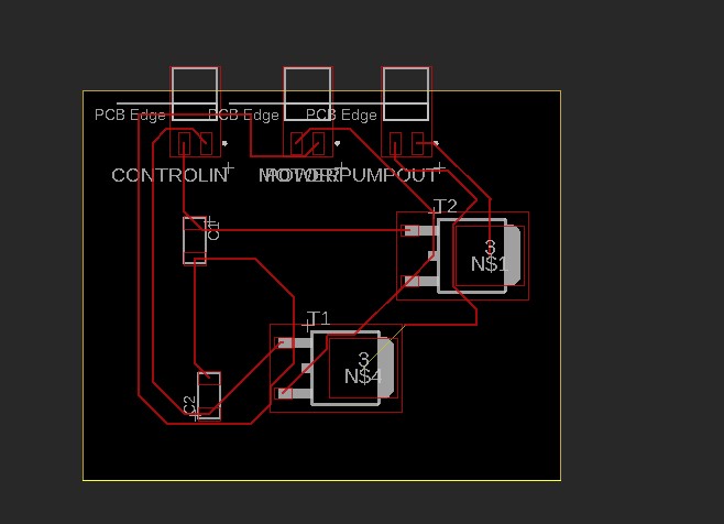
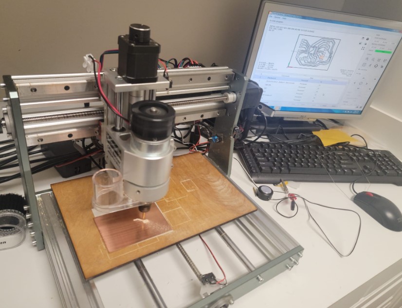
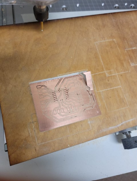
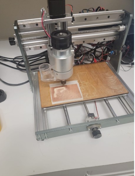
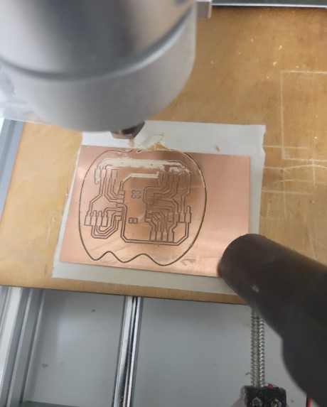
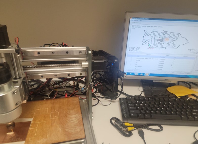
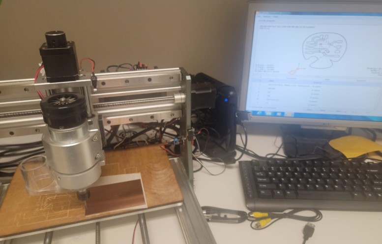
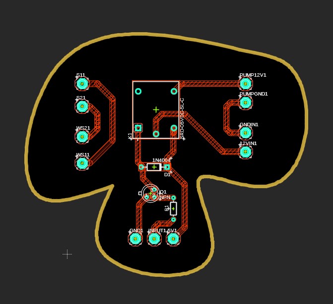
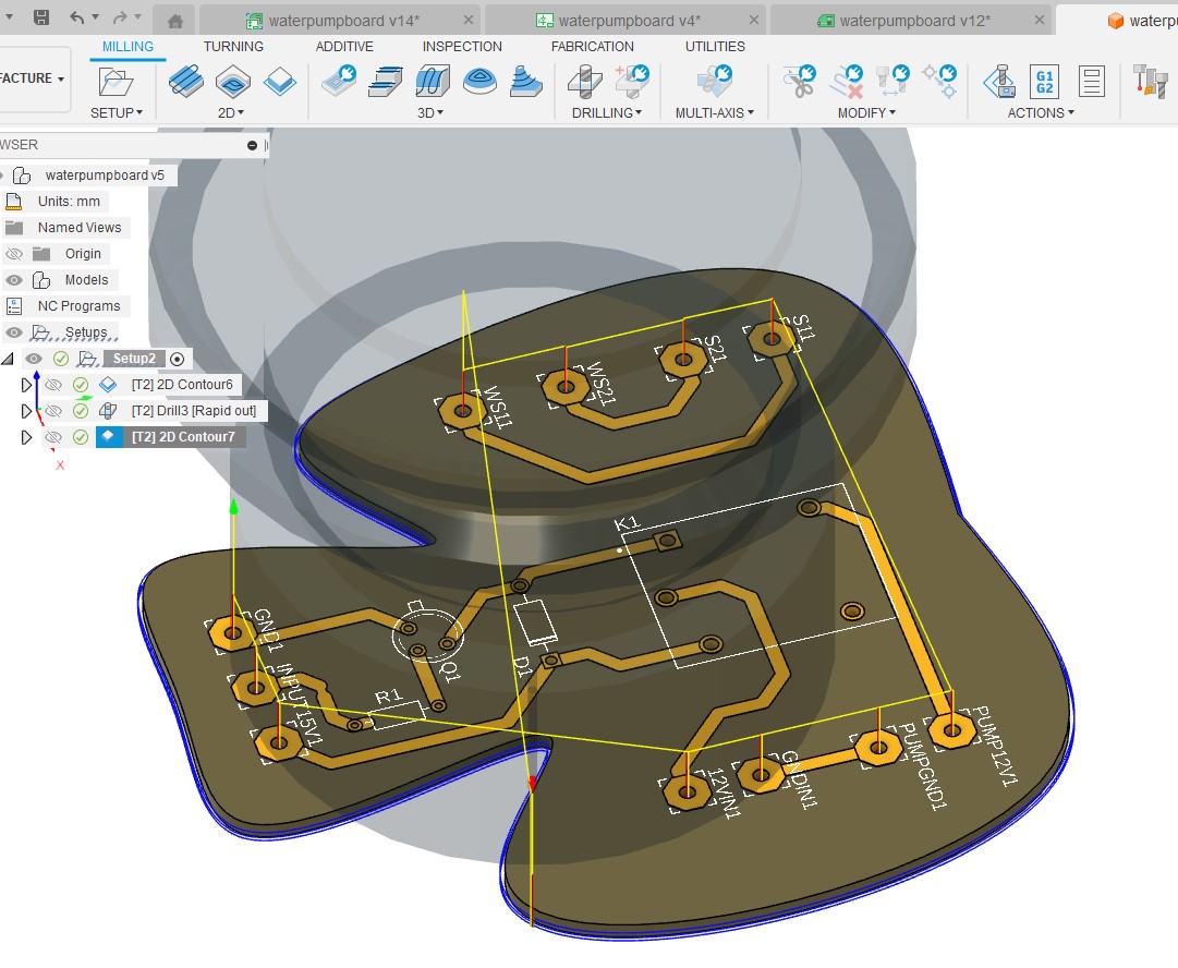
Motor: control board milling
Now I was ready to mill. I used the same set up with my Genmitsu 3020-Pro-Max from last week here
The tool path looked good
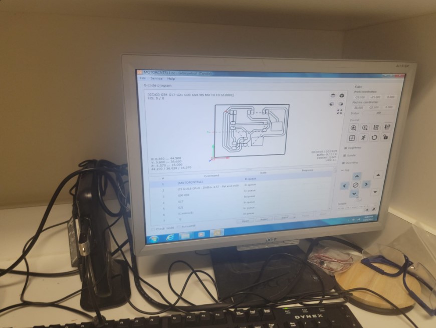
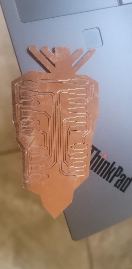
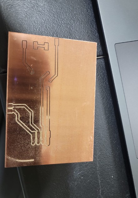
Got to cutting using a 0.8mm end mill
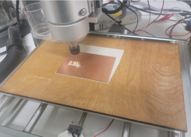
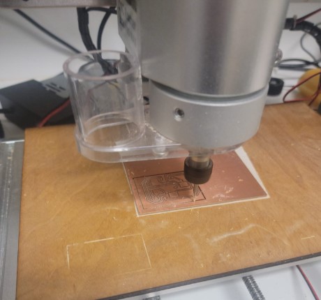
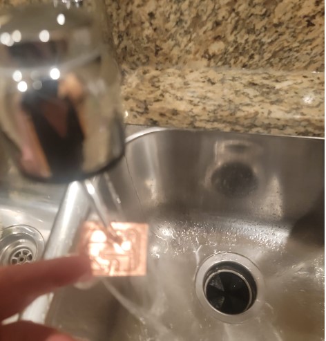
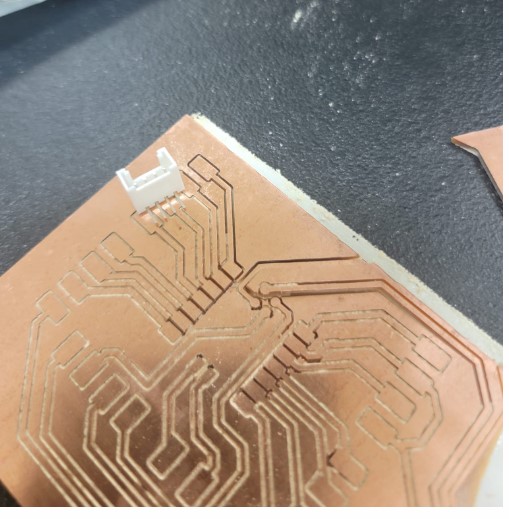
I deburred and washed the board
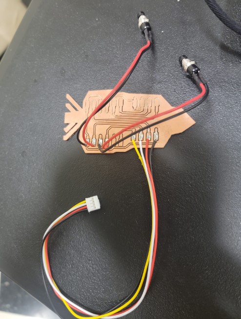
Now we are ready to stuff and solder
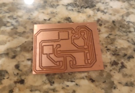
Here are all the components
And we are ready to test
After stripping the connectors on a number of boards and after rethinking the machine design I decided the break this board into 2 one for the motor and one for the pump.
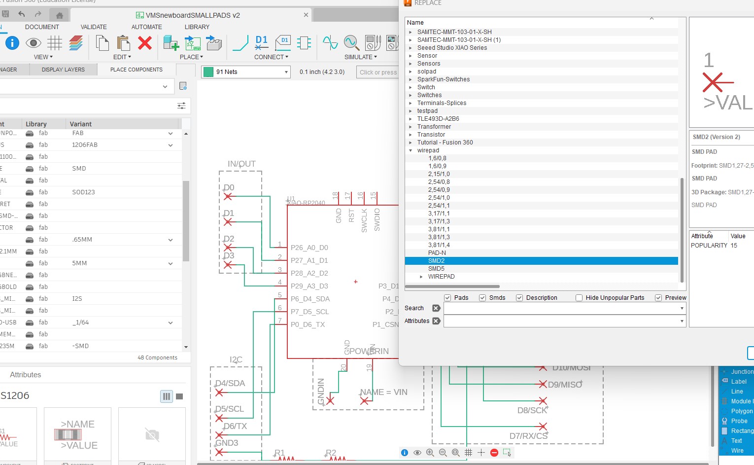
I also increased the side of my traces to 30mil and replace the pad for my connector with A better connector from the fab library
I started testing the board and it seemed like now matter what I did the Sources and Drain of the transistor was always connected.
I checked for shorts, I added a pull down resistor to ensure the gate is 0 and not joy. The source and drain are connected.
I went back to the lab and got another 2 transisotr (the lab only had 3 of them) and they all seemed to do that same.
I reviewed them with my instructure and fellow student who is an electrical engineer and they could not find why it was acting this way other then it may be a bad batch of transistors. We put in an order for some more and for now this part of the project is on hold until the arrive.
While this effort was on hold we completed Machine Building week and that changed my mind on how to set up the motor.
Motor: Moving to direct drive
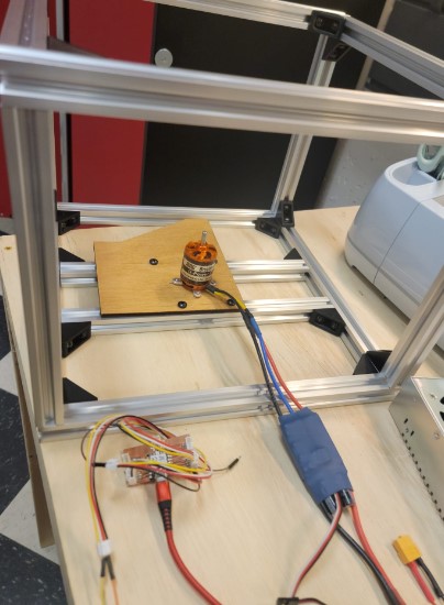
After a success full machine week I got appreciation for the out runner motor capabilities and so I decided to try and mount the plat directly on a out runner motor and see if that work.
I had a outrunner motor in the lab that was bigger then the one we used in machine week and I think would work well.
Here is it spec:
I coupled that with a large ESC with the following user manual
I decided to test the motor using a potentiometer to control the speed so I can find out what are good speeds for my final project.
I set up the mounting bracket on the motor
I used a scrap piece of wood to mount the motor onto the frame
Motor: ESC wiring
Power: The motor will connect directly to the 0-24V power supply I have
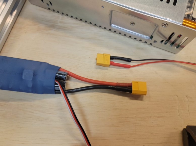
ESC control: the ESC will be connect to the BOD via 3 wires: 5V / GND / and PMW from pin D0
Motor: Arduino code for potentiometer control
I wired a potentiometer to analog input A1 and the 5V/GND and ran the following code:
# include <Servo.h>

// create a Servo object to control the ESC
Servo esc;

int potVal;

void setup() {
  // set the baud rate for serial communication
  Serial.begin(9600);

  // attach the ESC to pin 9
   esc.attach(9, 1000, 2000); // the second and third parameters are the minimum and maximum pulse widths
  int potVal;
 esc.write(0); //arm ESP
 delay(1000);
}

void loop() {
  // set the speed to half of the maximum (which is 180)

 potVal = analogRead(A1); // read input from potentiometer.

int speed  = map(potVal,0, 1023, 0, 180); // maps potentiometer values to PWM val

  // send the speed to the ESC
  esc.write(speed);

   // print the speed to the serial monitor
  Serial.print("Speed: ");
  Serial.println(speed);

  // pause for a moment before starting again
}
This will both printout in the serial monitor the speed variable so I can see the which value I would want to use in the final code.
Motor: First time ESC calibration
When you plug the ESC in for the first time it need to go via a calibration process.
1) You put it to full throttle
2) Connect motor to power
3) Move to zero throttle
You can see the motor first run
Motor: speed test
I mounted the plate on the motor and ran the motor
I started moving the potentiometer while look at the serial monitor to see the speed.
Answer is pretty straight forward.
The lowest speed that will run is with the Servo Angle value of 24.
A good increased speed for drying is 40.
These will be the two value I will use in the cycles
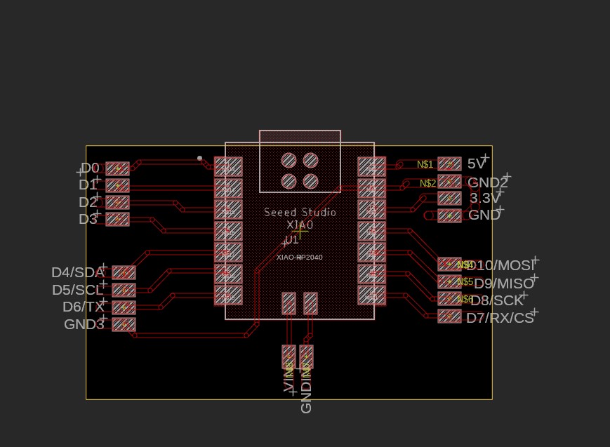
Electronics: New board - Moving to RO2040
After a while I decided to move to a working iwht th eRP2040
I am going to follow the same break out board design and so I started to work on a schematic. I am planning to use 4 pin wire to board connectors and 2 pin for the power as an alternative to the USBC.
I have the 2D Board set up
Now we are ready to mill

Here we are in action
Board is ready
The pad I was using were too big for the connector sockets I had
I replaced the connectors
realigned the groupings by breakout board
Layout is ready for tool path
Looks good
ready to mill
A good pinout type map
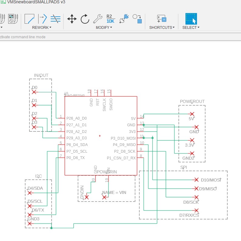
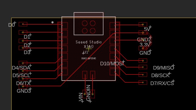
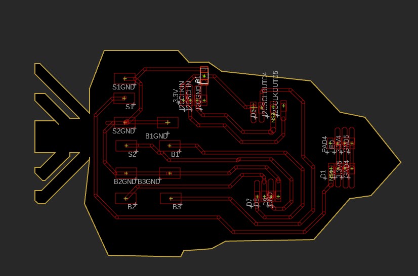
After working on the other breakout boards I had to comeback and redesign this main control board for 2 reasons:
-
connectors - I was committed to clean wiring and use off wire to board sockets. I had a much better map of the breakout board needs and connection and so I need a new foot print to set the sockets up correctly
-
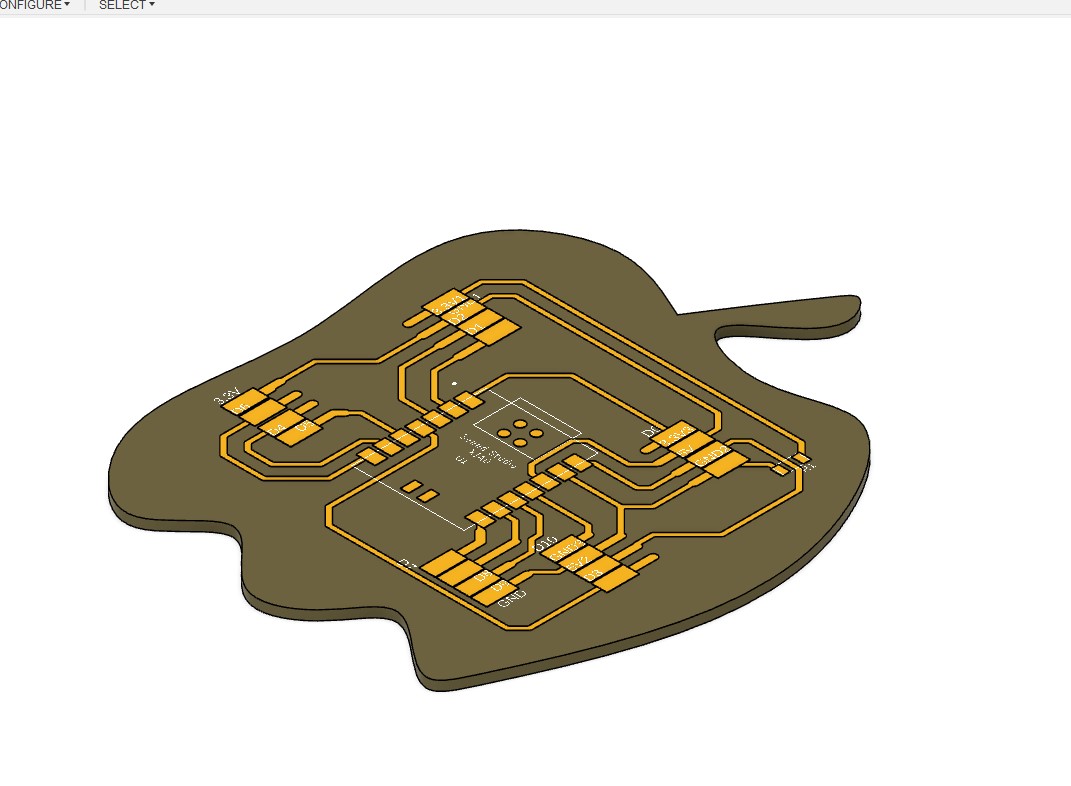
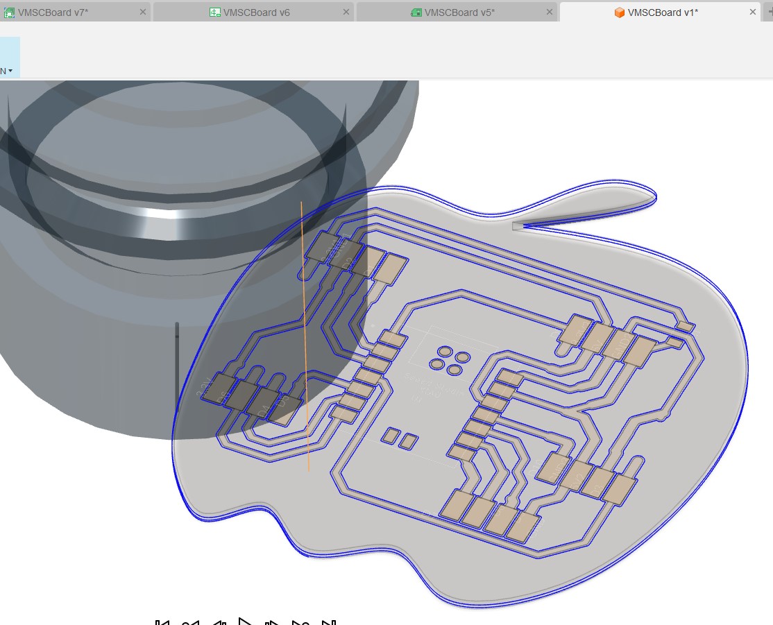
Shape - I started with the vegetable shapes and wanted to come back with a pepper shape
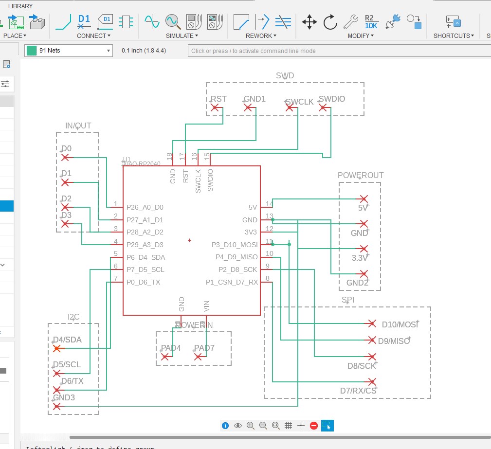
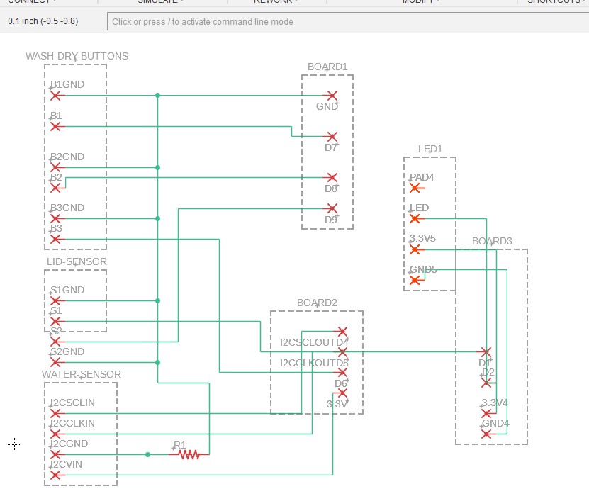
I used the systems map at the top as a guide to which pins need to connect to each board.
I created a new schematic
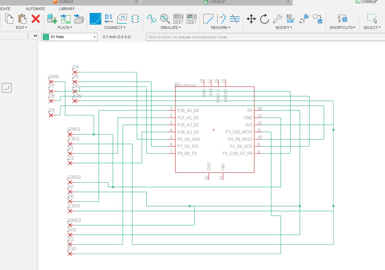
Layout was pretty straight forward but had to use a jumper for GND to one of the sockets
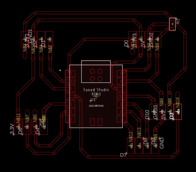
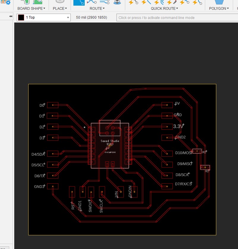
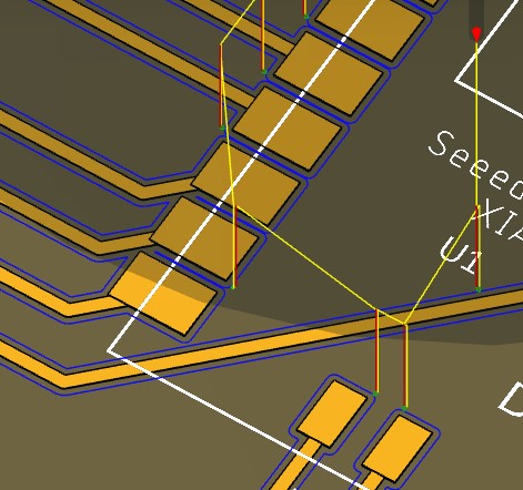
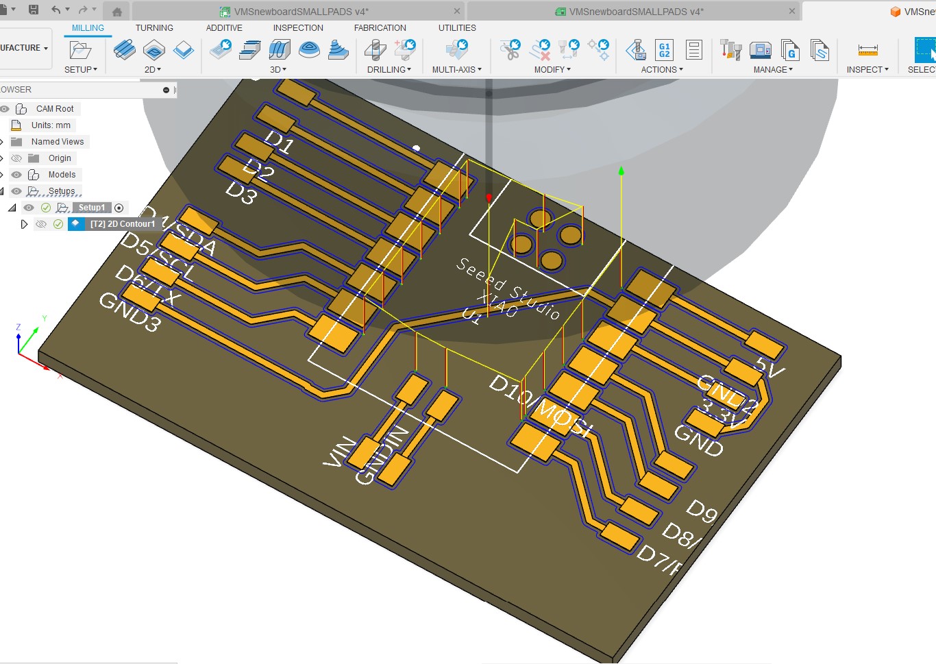
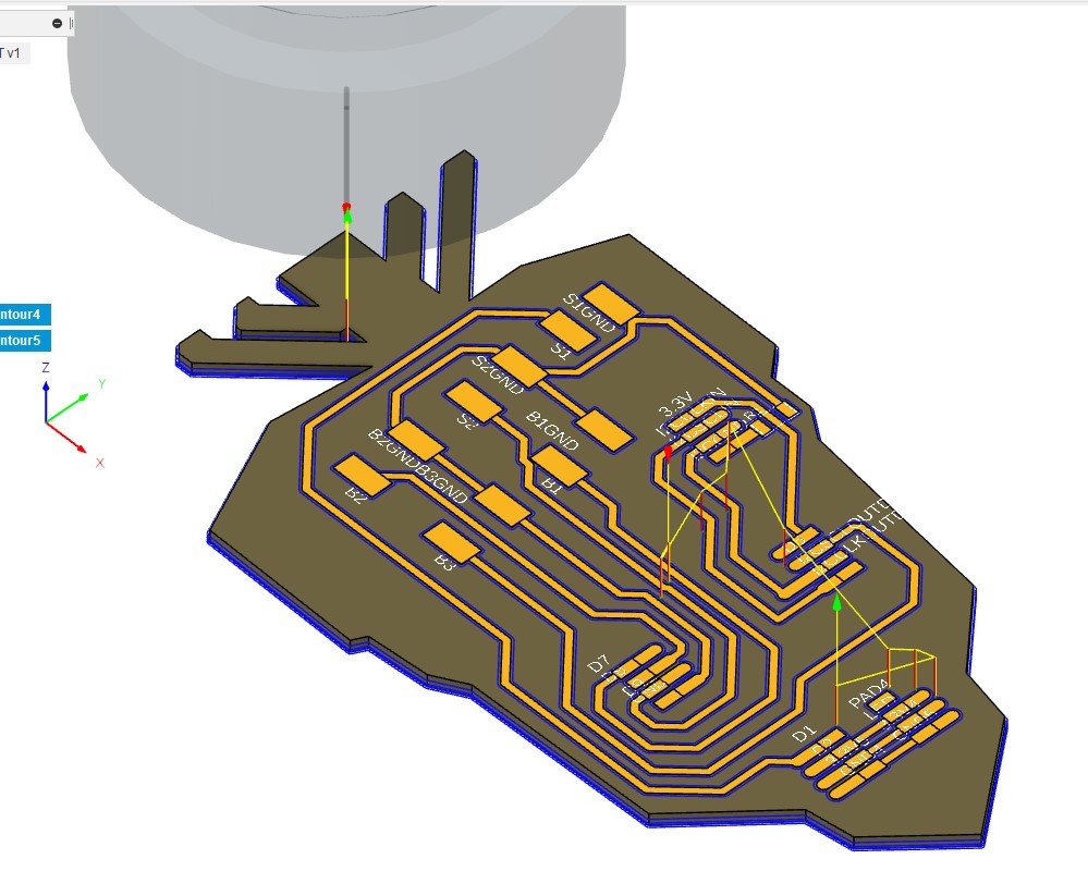
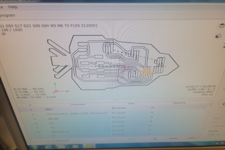
3D board ready to mill
I had to adjust to spacing betweek the pads for the 0.5mm milling bit I have.
I made the same mistake using the pads that are too big for the sockets
A quick replacement to fit the sockets
And we are ready to mill
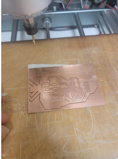
Here we go
And we are ready to stuff and solder
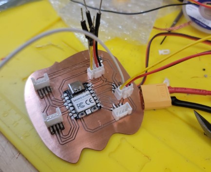
Board ready to go
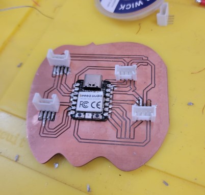
Sockets are working well
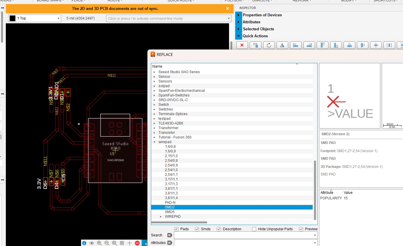
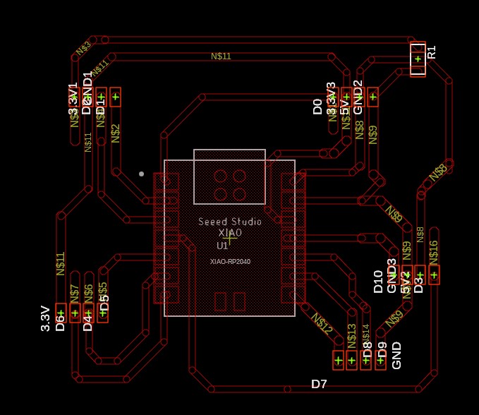
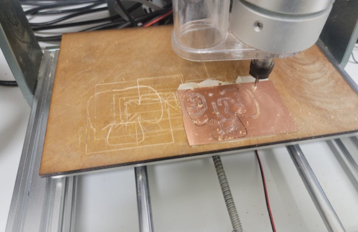
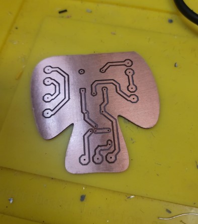
Electronics: Button/sensor breakout board
To connected the control button, lid sensor and water level sensor I created a break out board.
I started with a basic schematic
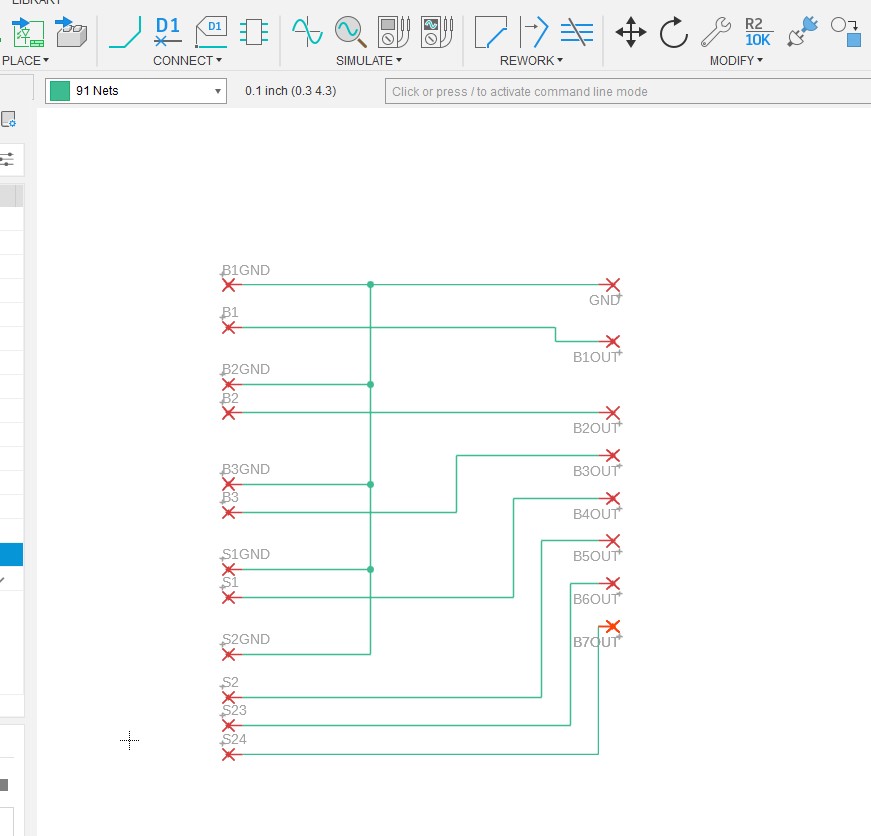
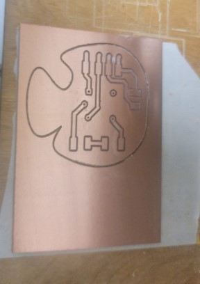
I think routed the board and decided to make the board the shape of a carrot.
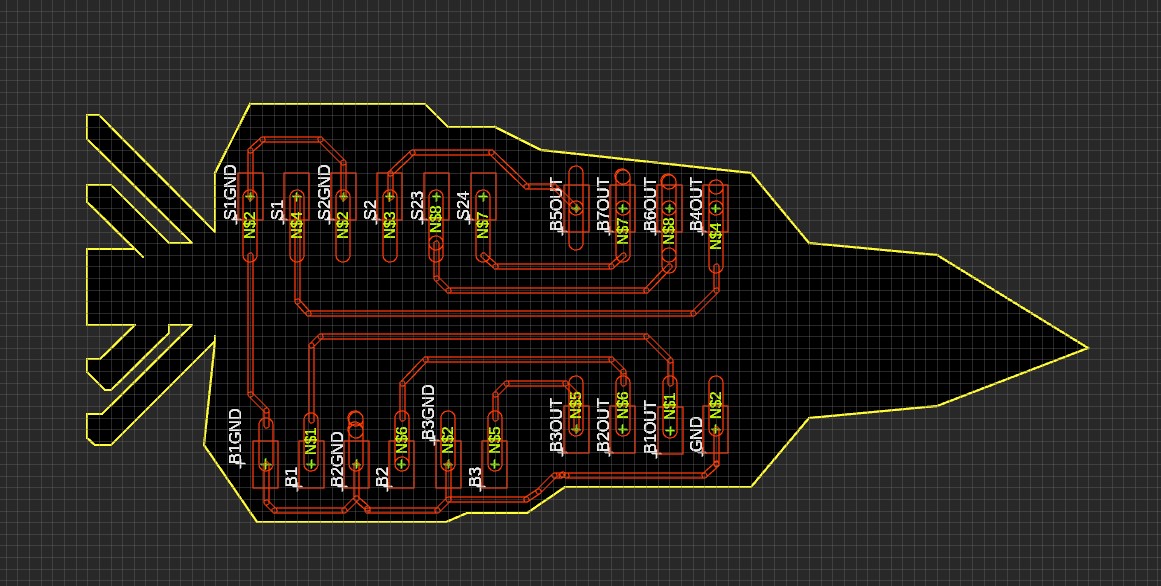
I had to shorten the carrot so it fit on the PCB I had.
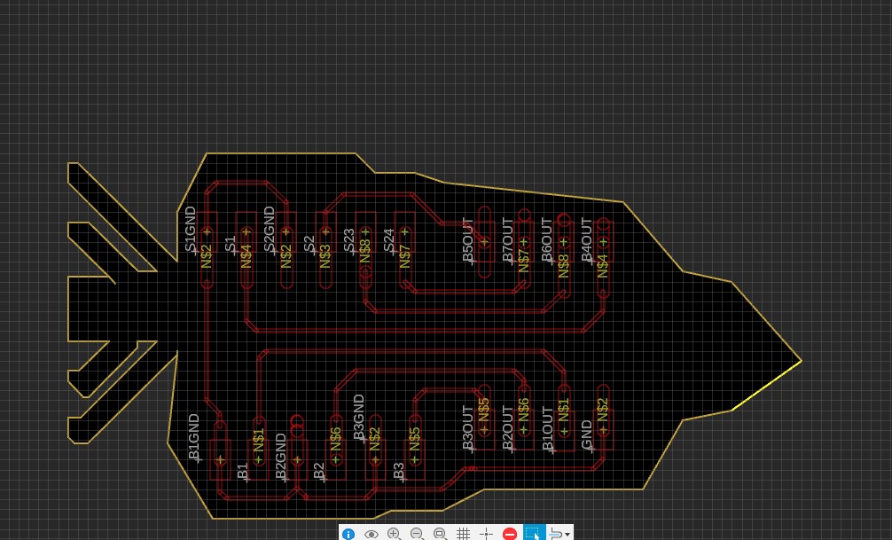
And now it is ready to mill
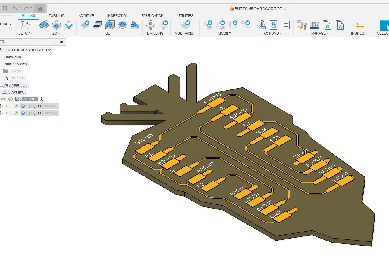
Here we go
No we just have to clean it up
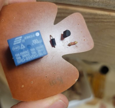
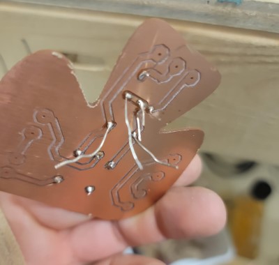
I got that parts soldered in and set up with the motor.
I soldered the wire for the button as well as the 4 pin connector to the button board
Now I needed to redesign this board for 2 reasons
-
Add I2C connections for the water level sensor
-
Added 2 sockets to connect to the main board for the buttons and lid and water sensor.
Here is the new schematics
New board layout and tracing
Ready to mill
Set up done
New board ready to stuff and solder
Here it is mounted in the box with all the sockets soldered in place
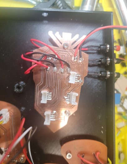
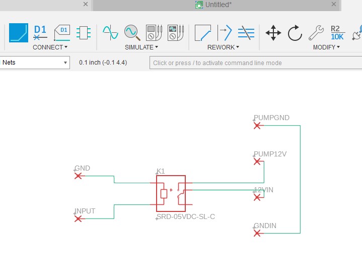
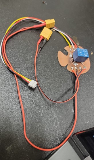
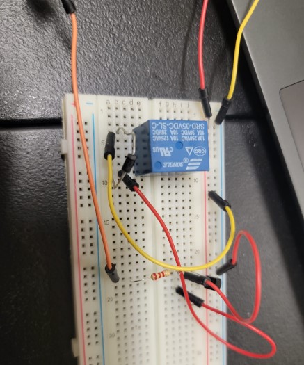
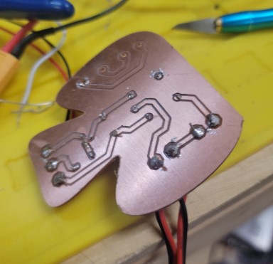
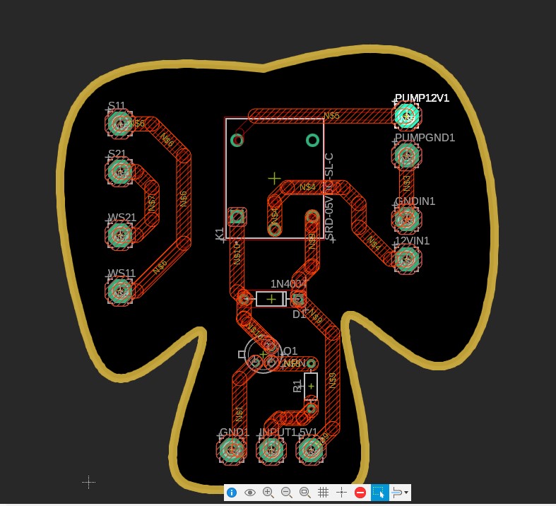
Electronics: Pump breakout board
I initialy toughts this should be pretty traight forward.
Breakout board would drive a relay with a GPIO from the main board that would be activated but the button push similar to the motor. The relay would connect the pump to the 12V power supply.
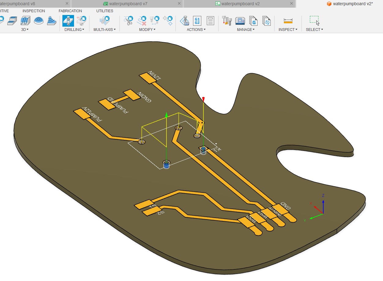
I decided to use a mushroom design
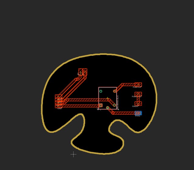
got it ready to cut
I misjudged the size and so after overshotting
I redesigned the board
Got it cut
Now it fit
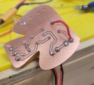
Got it stuffed and soldered
When I pressed the button the motor turned byut instead of the rely switching to turn on the pump nothing happened.
I got out the multimeter and saw that when not connected to the relay the D1 pin went up to 3.3V when I pressed the button but when connected to the relay it only went to 1.8V and the relay did not activate.
I researched this I found out the RP2040 GPIO do not have enough current to drive the relay so I needed to make a driver.
I found this basic driver schematic on the raspberrypi forum
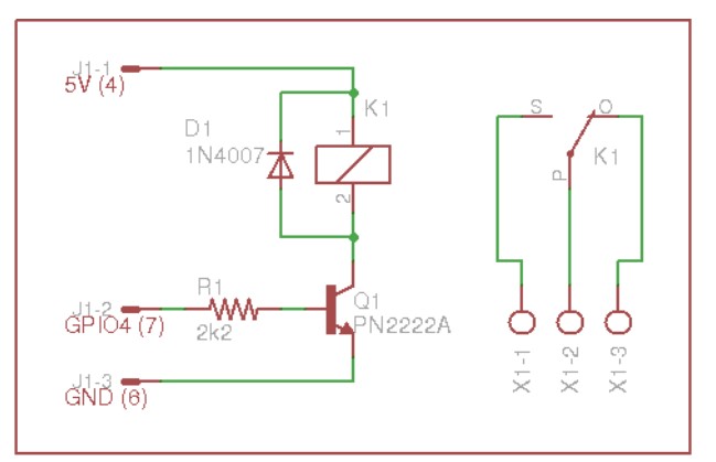
I only had through hole components to make this and so decided to make a through hole board for this. I never made one and so was interested to see how it worked.
First I tested it on a breadboard to make sure it worked
Updated the schematic to include the driver.
Retraced everything
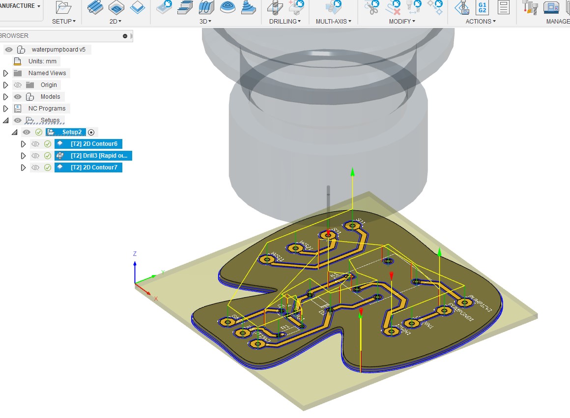
Got it ready to mill
Milling took a few attempts as this was the first time I was using the drilling function and I kept setting the Z too low (this is a manual process on my mill) and the drill would break the trace
I got a hang of the calibration needed and we have a board
Added components
Soldered
And we are ready to test
The test showed me that I ended up connected to the Normally open legs of the relay vs. the Normally closed and so the pump ran contently. The mistake was due to my not flipping the components to the other side of the board for the drill through layout.
I ended up cutting that trace with a knife and added a jumper which worked well.
I also redesigned the board and will remill once if needed later
Now we are ready to test it .... we have water flow!
Power supply
I got this power supply from amazon as I was not sure which motor pump i was going ot use initially the variable aspect of this power supply was useful.
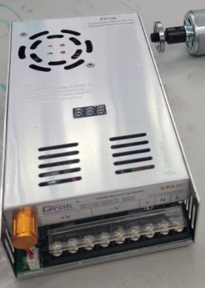
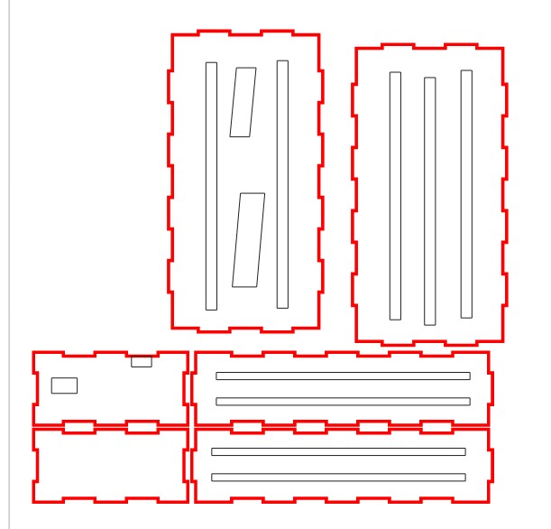
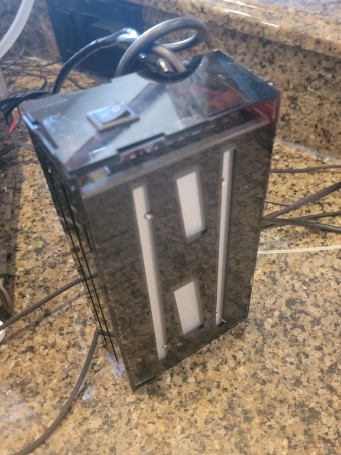
I then cut a box cover for it and added a power switch.
The power supply had not power switch so I added one which will be the on/off switch for the whole machine
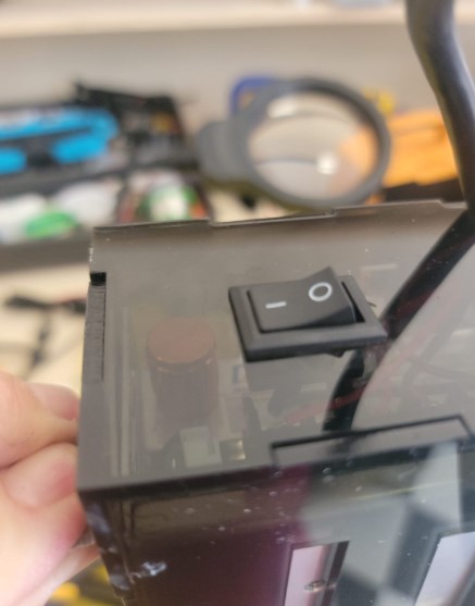
And here it is assembled
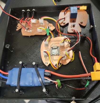
Electronics: System integration
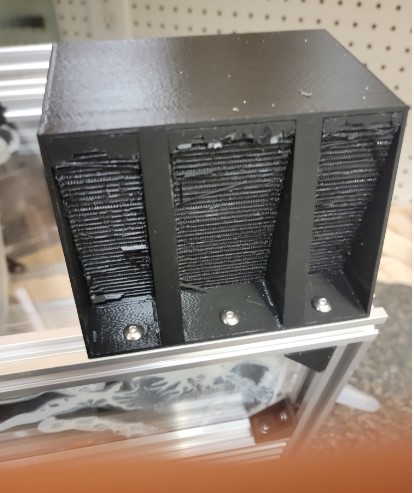
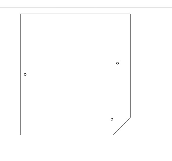
I decided to make a box that will mount on to the side of the machines and will have the control board and breakout board in it.
I added screw holds for mounting the board / ESC and some holes for wires to come in and out
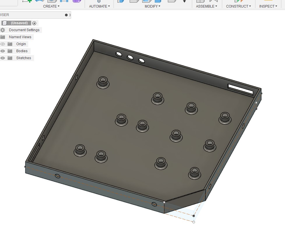
Ready to print
Added some M3 bolts to secure the boards
It fits onto the side nicely
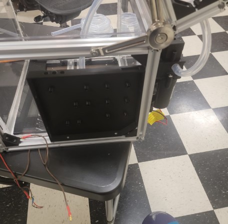
This ended up a little too small and so I had to redo a bigger version. I also added slots to secure wires and screw holes for the cover
Then cut the cover from plexiglass
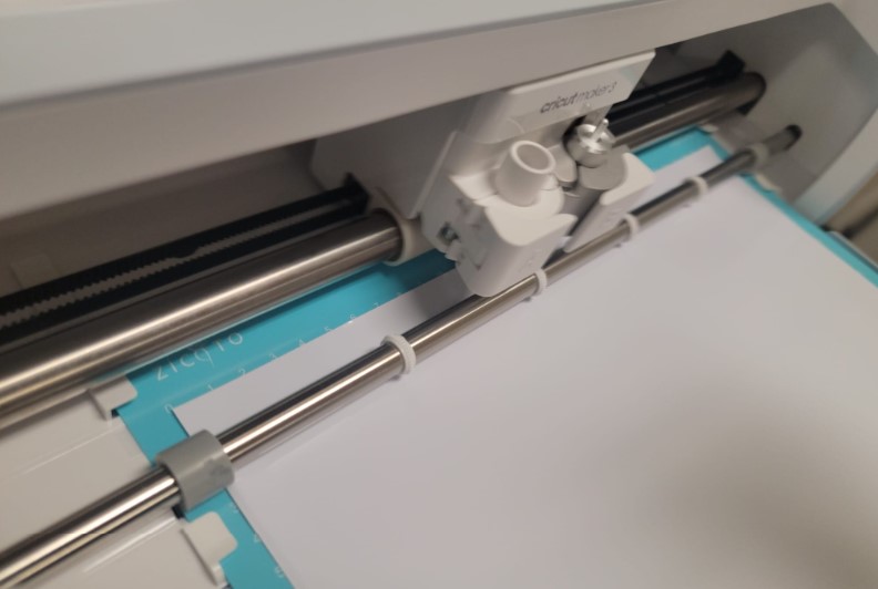
I then used a vinyl cutter to make labels
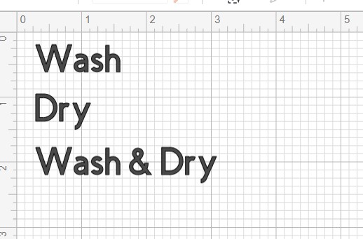
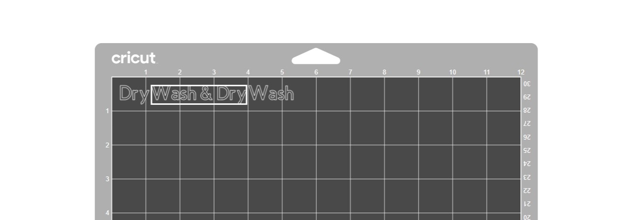
quick cut on the cutter
Cut out the labels
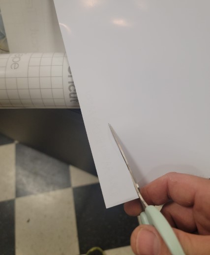
Some clean up
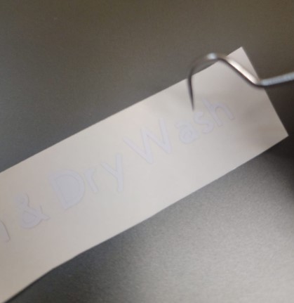
Transfer tape
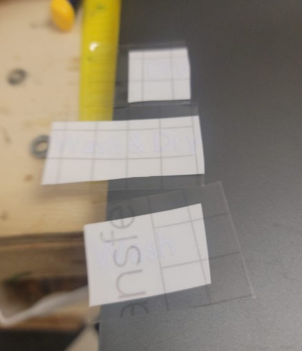
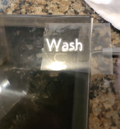
Lable in place
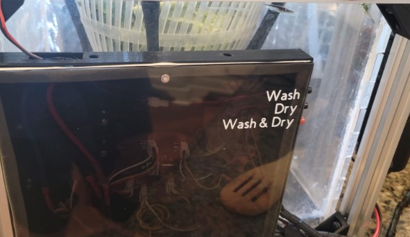
and here it is all integrated into one box
Electronics: Sensors
Lid Sensor
The open lid sensor is a simple mounted switch
I used the M3 T nuts I had to mount the switch directly onto the frame.
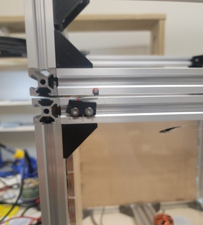
I used the casted plastic mushroom I casted from Molding and Casting week as the counter edge on the LID
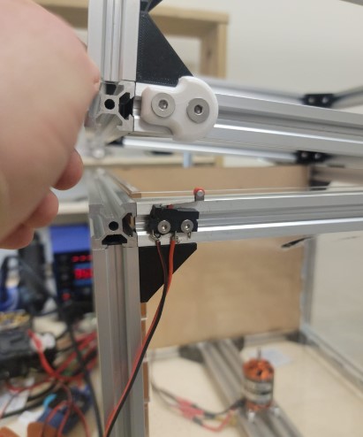
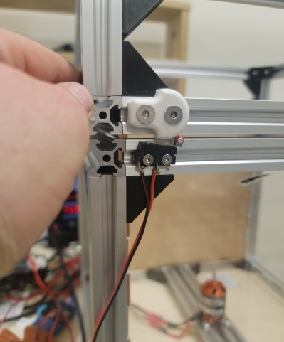
The wiring is run through the button break out board
And here you can see it in action
Electronics: Water level sensor
I got a few of the following sensors off Amazon:
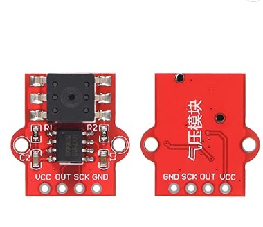
Unfortunately there was not documentation or links on amazon to documentation. I used google lens to search for the picture of the sensor and found a good tutorial
Turns out this is a HX710
I got it wired into the I2C on the board and used the following test code to read the measurements.
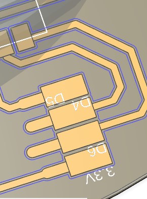
const int HX_OUT_PIN = D4;
const int HX_SCK_PIN = D5;

enum HX_MODE { NONE, DIFF_10Hz, TEMP_40Hz, DIFF_40Hz};
const byte HX_MODE = DIFF_40Hz;

void setup() {
  pinMode(HX_SCK_PIN, OUTPUT);
  pinMode(HX_OUT_PIN, INPUT);
  Serial.begin(9600);
}

void loop() {
  Serial.println(readHX());
}

unsigned long readHX() {

  // pulse clock line to start a reading
  for (char i = 0; i < HX_MODE; i++) {
    digitalWrite(HX_SCK_PIN, HIGH);
    digitalWrite(HX_SCK_PIN, LOW);
  }

  // wait for the reading to finish
  while (digitalRead(HX_OUT_PIN)) {}

  // read the 24-bit pressure as 3 bytes using SPI
  byte data[3];
  for (byte j = 3; j--;) {
    data[j] = shiftIn(HX_OUT_PIN, HX_SCK_PIN, MSBFIRST);
  }

  data[2] ^= 0x80;  // see note

  // shift the 3 bytes into a large integer
  long result;
  result += (long)data[2] << 16;
  result += (long)data[1] << 8;
  result += (long)data[0];

  return result;
}
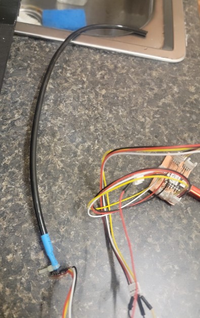
I then got it wired up
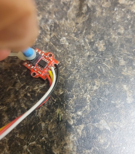
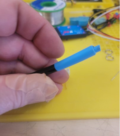
I used some heat shrink to connect a air pump hose to the sensor tip
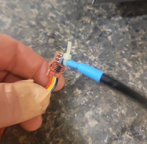
And here it is ready to go into water reservoir
and here it is in action as I drain the water reservoir
Code basic set up
To keep this week in sync with my final project I decided to test a set up for the basic VMS functionality replacing the water pump and motor with LED and the sensors with buttons.
Here is the functionality I was aiming for:
| Button | Label | FUnctionality |
|---|---|---|
| Button 1 | Wash cycle | 1. Check Lid / Water sensor -> 2. Turn on Water pump and motor for a set time |
| Button 2 | Dry cycle | 1. Check Lid -> 2. Turn on motor for a set time |
| Button 3 | Total cycle | 1. Run Wash cycle -> 2. Run Dry cycle |
| Sensors | If either sensor is triggered then stop and turn on error LED |
Here is my updated code:
// Define the pin numbers for the sensors and actuators
const int LED_PIN = 7;
const int WASH_BUTTON_PIN = 11;
const int DRY_BUTTON_PIN = 10;
const int FULL_BUTTON_PIN = 9;
const int WATER_SENSOR_PIN = 2;
const int LID_SENSOR_PIN = 3;
const int DRUM_PIN = 4;
const int WATER_PUMP_PIN = 5;

void setup() {
    Serial.begin(9600);
    pinMode(LED_PIN, OUTPUT);
    pinMode(WASH_BUTTON_PIN, INPUT);
    pinMode(DRY_BUTTON_PIN, INPUT);
    pinMode(FULL_BUTTON_PIN, INPUT);
    pinMode(WATER_SENSOR_PIN, INPUT);
    pinMode(LID_SENSOR_PIN, INPUT);
    pinMode(DRUM_PIN, OUTPUT);
    pinMode(WATER_PUMP_PIN, OUTPUT);
}

void loop() {
    // Wait for the wash button press
    if (digitalRead(WASH_BUTTON_PIN) == HIGH) {
        // Check the water level and lid status
        if (digitalRead(WATER_SENSOR_PIN) == LOW && digitalRead(LID_SENSOR_PIN) == LOW) {
            // Start the wash cycle
            digitalWrite(DRUM_PIN, HIGH);
            digitalWrite(WATER_PUMP_PIN, HIGH);
            delay(600);
            digitalWrite(DRUM_PIN, LOW);
            digitalWrite(WATER_PUMP_PIN, LOW);
              delay(400);
              digitalWrite(WATER_PUMP_PIN, HIGH);
           delay(400);
            digitalWrite(WATER_PUMP_PIN, LOW);
        } else {
            Serial.println("Not enough water or lid is open.");
                        digitalWrite(LED_PIN, HIGH);

        }
    }

    // Wait for the dry button press
    if (digitalRead(DRY_BUTTON_PIN) == HIGH) {
        // Start the slow spin
                if (digitalRead(LID_SENSOR_PIN) == LOW) {

        digitalWrite(DRUM_PIN, HIGH);
        delay(600);

        // Start the fast spin
        digitalWrite(DRUM_PIN, LOW);
        delay(300);
        digitalWrite(DRUM_PIN, HIGH);
        delay(300);
        digitalWrite(DRUM_PIN, LOW);
                }     else {
            Serial.println("lid is open.");
                        digitalWrite(LED_PIN, HIGH);

        }
    }

    // Wait for the full cycle button press
    if (digitalRead(FULL_BUTTON_PIN) == HIGH) {
        // Perform the wash cycle
        if (digitalRead(WATER_SENSOR_PIN) == LOW && digitalRead(LID_SENSOR_PIN) == LOW) {
            // Start the wash cycle
            digitalWrite(DRUM_PIN, HIGH);
            digitalWrite(WATER_PUMP_PIN, HIGH);
            delay(600);
            digitalWrite(DRUM_PIN, LOW);
            digitalWrite(WATER_PUMP_PIN, LOW);
                delay(400);
            digitalWrite(WATER_PUMP_PIN, HIGH);
           delay(400);
            digitalWrite(WATER_PUMP_PIN, LOW);
        } else {
            Serial.println("Not enough water or lid is open.");
             digitalWrite(LED_PIN, HIGH);
            return;
        }

        // Perform the dry cycle
        // Start the slow spin
        if (digitalRead(LID_SENSOR_PIN) == LOW) {
        digitalWrite(DRUM_PIN, HIGH);
        delay(200);

        // Start the fast spin
        digitalWrite(DRUM_PIN, HIGH);
        delay(200);
        digitalWrite(DRUM_PIN, LOW);
        delay(200);
        digitalWrite(DRUM_PIN, HIGH);
        delay(100);
        digitalWrite(DRUM_PIN, LOW);

       } else {
            Serial.println("Not enough water or lid is open.");
             digitalWrite(LED_PIN, HIGH);
            return;
        }

    }}
Here is the basic circuit I am planning
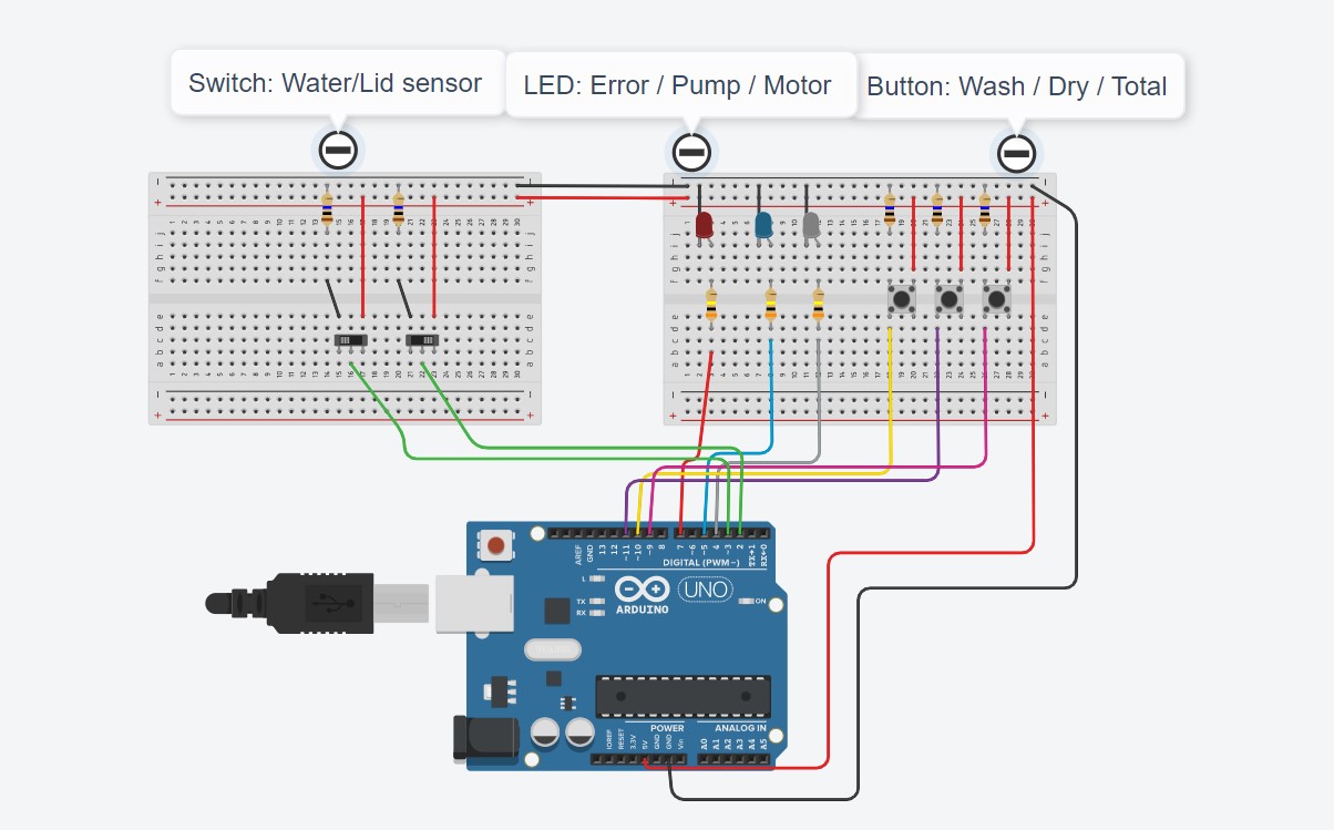
I followed this diagram (except for the different colored wires) and it went pretty smoothly
Here is the one I built in action:
Final code
Here is the final code once I got all the wiring, pins and sensors locked in.
# include <Servo.h>

// Define the pin numbers for the sensors and actuators
const int LED_PIN = D4;
const int WASH_BUTTON_PIN = D8;
const int DRY_BUTTON_PIN = D6;
const int FULL_BUTTON_PIN = D7;
const int WATER_SENSOR_PIN = D2;
const int LID_SENSOR_PIN = D1;
const int DRUM_PIN = D0;
const int WATER_PUMP_PIN = D3;
const int DRUM_SLOW = 28;
const int DRUM_FAST = 29;
const int DRUM_STOP = 0;
int potVal;
Servo esc;
const int HX_OUT_PIN = D4;
const int HX_SCK_PIN = D5;
const int washdelay = 1500;
const int drydelay = 1000;
const int waterlevel = 1234000;
int waterSensorState = HIGH;

enum HX_MODE { NONE, DIFF_10Hz, TEMP_40Hz, DIFF_40Hz};
const byte HX_MODE = DIFF_40Hz;


void setup() {
  pinMode(HX_SCK_PIN, OUTPUT);
  pinMode(HX_OUT_PIN, INPUT);
  pinMode(LED_PIN, OUTPUT);
  pinMode(WASH_BUTTON_PIN, INPUT_PULLUP);
  pinMode(DRY_BUTTON_PIN, INPUT_PULLUP);
  pinMode(FULL_BUTTON_PIN, INPUT_PULLUP);
  pinMode(WATER_SENSOR_PIN, INPUT_PULLUP);
  pinMode(LID_SENSOR_PIN, INPUT_PULLUP);
  pinMode(DRUM_PIN, OUTPUT);
  pinMode(WATER_PUMP_PIN, OUTPUT);
  Serial.begin(9600);
  esc.attach(DRUM_PIN, 1000, 2000);
  esc.write(DRUM_STOP);
  delay(1000);

}

void loop() {
    // Wait for the wash button press
    Serial.println(readHX());
 if (readHX() < waterlevel) {
    waterSensorState = LOW;
  } else {
    waterSensorState = HIGH;
  }

  digitalWrite(WATER_SENSOR_PIN, waterSensorState);


if (digitalRead(WASH_BUTTON_PIN) == LOW) {
        // Check the water level and lid status
        if (digitalRead(WATER_SENSOR_PIN) == HIGH && digitalRead(LID_SENSOR_PIN) == LOW) {
            // Start the wash cycle
            esc.write(DRUM_SLOW);
            Serial.println("wash");
            digitalWrite(WATER_PUMP_PIN, HIGH);
            delay(washdelay);
            //esc.write(DRUM_STOP);
            digitalWrite(WATER_PUMP_PIN, LOW);
              delay(washdelay/3);
              digitalWrite(WATER_PUMP_PIN, HIGH);
              esc.write(DRUM_FAST);

           delay(washdelay);
            digitalWrite(WATER_PUMP_PIN, LOW);
            esc.write(DRUM_STOP);

        } else {
            Serial.println("Not enough water or lid is open.");
                        digitalWrite(LED_PIN, HIGH);

        }
    }

       // Wait for the dry button press
    if (digitalRead(DRY_BUTTON_PIN) == LOW) {
        // Check the water level and lid status
        if (digitalRead(LID_SENSOR_PIN) == LOW) {
            // Start the dry cycle
            esc.write(DRUM_SLOW);
            Serial.println("Dry");
            delay(drydelay);

              esc.write(DRUM_FAST);

           delay(drydelay);
            esc.write(DRUM_STOP);

        } else {
            Serial.println("lid is open.");
                        digitalWrite(LED_PIN, HIGH);

        }
    }

  // Wait for the full button press
    if (digitalRead(FULL_BUTTON_PIN) == LOW) {
        // Check the water level and lid status
        if (digitalRead(WATER_SENSOR_PIN) == HIGH && digitalRead(LID_SENSOR_PIN) == LOW) {
            // Start the wash cycle
            esc.write(DRUM_SLOW);
            Serial.println("washfull");
            digitalWrite(WATER_PUMP_PIN, HIGH);
            delay(washdelay);
            //esc.write(DRUM_STOP);
            digitalWrite(WATER_PUMP_PIN, LOW);
              delay(washdelay/3);
              digitalWrite(WATER_PUMP_PIN, HIGH);
              esc.write(DRUM_FAST);

           delay(washdelay);
            digitalWrite(WATER_PUMP_PIN, LOW);
            esc.write(DRUM_STOP);
           delay(washdelay/3);
            esc.write(DRUM_SLOW);
            Serial.println("Dryfull");
            delay(drydelay);

              esc.write(DRUM_FAST);

           delay(drydelay);
            esc.write(DRUM_STOP);

        } else {
            Serial.println("Not enough water or lid is open.");
                        digitalWrite(LED_PIN, HIGH);

        }
    }


    if (digitalRead(WASH_BUTTON_PIN) == LOW) {
        // Check the water level and lid status
        if (digitalRead(WATER_SENSOR_PIN) == HIGH && digitalRead(LID_SENSOR_PIN) == LOW) {
            // Start the wash cycle
            esc.write(DRUM_SLOW);
            Serial.println("wash");
            digitalWrite(WATER_PUMP_PIN, HIGH);
            delay(washdelay);
            esc.write(DRUM_STOP);
            digitalWrite(WATER_PUMP_PIN, LOW);
              delay(washdelay/3);
              digitalWrite(WATER_PUMP_PIN, HIGH);
              esc.write(DRUM_FAST);

           delay(washdelay);
            digitalWrite(WATER_PUMP_PIN, LOW);
            esc.write(DRUM_STOP);

        } else {
            Serial.println("Not enough water or lid is open.");
                        digitalWrite(LED_PIN, HIGH);

        }
    }

       // Wait for the dry button press
    if (digitalRead(DRY_BUTTON_PIN) == LOW) {
        // Check the water level and lid status
        if (digitalRead(LID_SENSOR_PIN) == LOW) {
            // Start the dry cycle
            esc.write(DRUM_SLOW);
            Serial.println("Dry");
            delay(drydelay);

              esc.write(DRUM_FAST);

           delay(drydelay);
            esc.write(DRUM_STOP);

        } else {
            Serial.println("lid is open.");
                        digitalWrite(LED_PIN, HIGH);

        }
    }

  // Wait for the full button press
    if (digitalRead(FULL_BUTTON_PIN) == LOW) {
        // Check the water level and lid status
        if (digitalRead(WATER_SENSOR_PIN) == HIGH && digitalRead(LID_SENSOR_PIN) == LOW) {
            // Start the wash cycle
            esc.write(DRUM_SLOW);
            Serial.println("washfull");
            digitalWrite(WATER_PUMP_PIN, HIGH);
            delay(washdelay);
            esc.write(DRUM_STOP);
            digitalWrite(WATER_PUMP_PIN, LOW);
              delay(washdelay/3);
              digitalWrite(WATER_PUMP_PIN, HIGH);
              esc.write(DRUM_FAST);

           delay(washdelay);
            digitalWrite(WATER_PUMP_PIN, LOW);
            esc.write(DRUM_STOP);
           delay(washdelay/3);
            esc.write(DRUM_SLOW);
            Serial.println("Dryfull");
            delay(drydelay);

              esc.write(DRUM_FAST);

           delay(drydelay);
            esc.write(DRUM_STOP);

        } else {
            Serial.println("Not enough water or lid is open.");
                        digitalWrite(LED_PIN, HIGH);

        }
    }

    }


unsigned long readHX() {

  // pulse clock line to start a reading
  for (char i = 0; i < HX_MODE; i++) {
    digitalWrite(HX_SCK_PIN, HIGH);
    digitalWrite(HX_SCK_PIN, LOW);
  }

  // wait for the reading to finish
  while (digitalRead(HX_OUT_PIN)) {}

  // read the 24-bit pressure as 3 bytes using SPI
  byte data[3];
  for (byte j = 3; j--;) {
    data[j] = shiftIn(HX_OUT_PIN, HX_SCK_PIN, MSBFIRST);
  }

  data[2] ^= 0x80;  // see note

  // shift the 3 bytes into a large integer
  long result;
  result += (long)data[2] << 16;
  result += (long)data[1] << 8;
  result += (long)data[0];

  return result;
}
Files for the project can be found here