The internet is network of networks and all of the agents are connected to different computers within a communications to network.
A network would be a system, that are connected between each of the elements.
Why to make them? Basically is two computer or microcontrollers talking to each other, it could be because we need to control something remotely or recive data from distance, or trigger things in parallel that can talk between each other.
The difference between networks and protocols is that a network is computers or microcontrolers talking to each other, while a protocol is the rules that they follow to talk to each other. Define by how the network works.
Types
Transmission media: Cable, optic or radio frequency (representation of the amount of cables)
Topology: this is how data flows and link between the devices, like in a ring (close) mesh, star fully connected* how internet looks today, line tree or bus.
Range:small networks within a system.
03Wired communication
Wired networking is the process of connecting devices to a network using physical cables.
Serial vs Parallel
The different option is classify by how the data is sent. Serial vs parallel communication.
Parallel being different cables to each pin, we need a wave to need all of those pins to be sincronize, having a signal or a pace depending on this data or the clock itseld. This was common in the past, needing a lot of pins, it needed to be quick to send a lot of data, like in video or printers.
While the serial interface, means less wires.Having one for data and another one to keep it sincronize(even this one is not asbolutely neccesary).
Synchronous vs asynchronous
It means the data is transfered with or without an external clock signal. In terms for the communication asynchronous is use as data sent without timing constrain the most known is RX/TX (serial.begin for example in arduino would start this type)it requires only two wires apart from a common ground.RX-TX (send data/recibe data) and TX-RX the other way around. This means that there has to be an agreement on some topics, like the speed of sending info and reciving, this is called baud rate.
UART stands for Universal Asynchronous Receiver/Transmitter.sending messages or like a secret code.
It sends messages one bit at a time, using a special code that both devices can understand. It's like sending letters through a special delivery service, except the letters are in binary code, which is a code made of ones and zeros.
The I2C protocol is kind of like that. It's a way for electronic devices, like sensors and microcontrollers, to talk to each other by passing messages through a special line called the I2C bus.
03
I2C Protocol
For the test I used this protocol, for multiple digital slave to communicate with the master. It is for short distances communications.
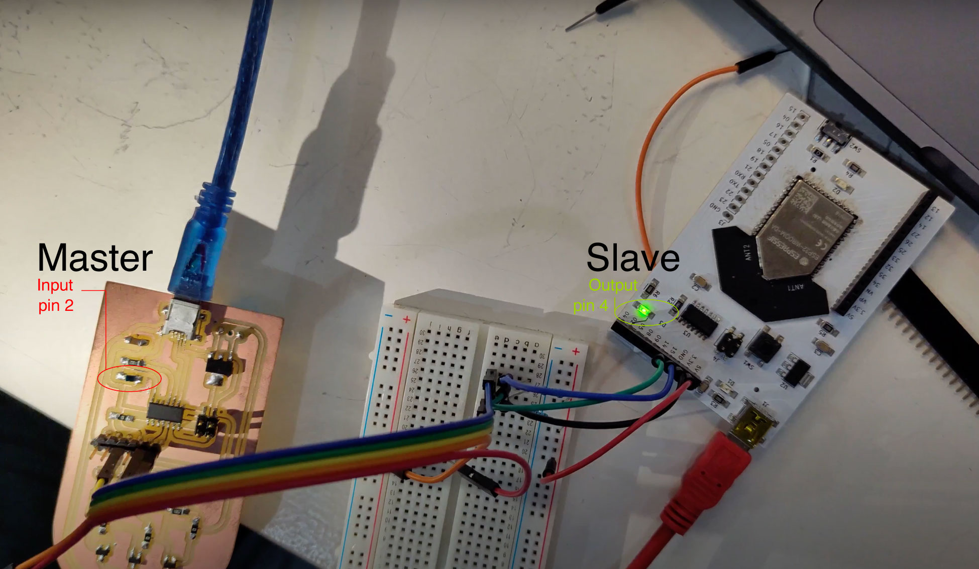
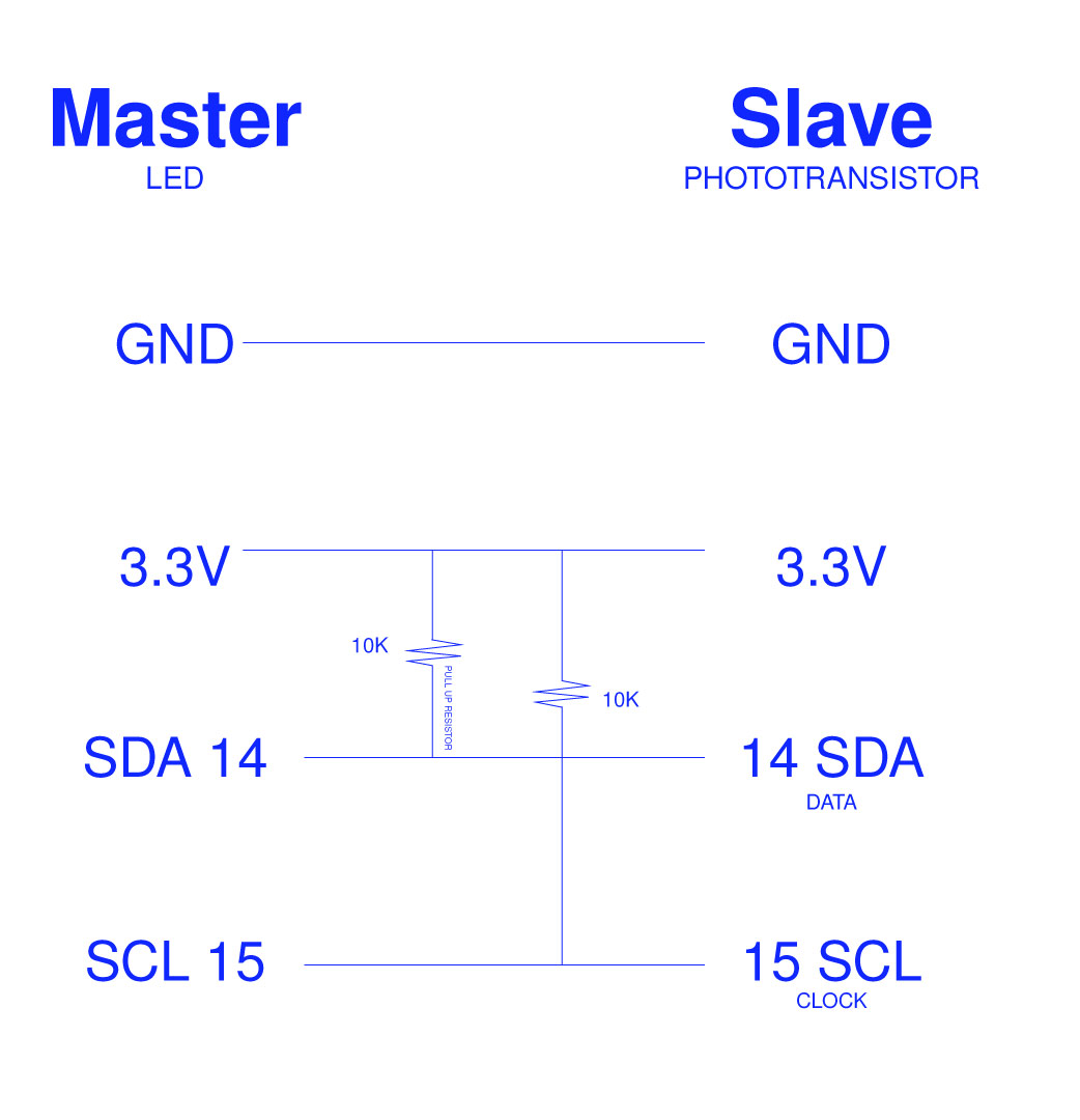
So for the test i'm using a Barduino acting as the master in an I2C communication with a slave device, in this case my PCBoard with a phototransistor to light up the led in the Barduino board. So is to requesting data from the slave device and control an analog output based on the data that is receiving.
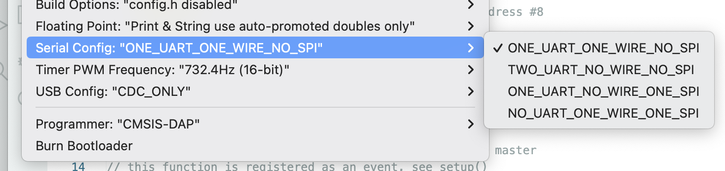
When open arduino, keep in mind to change the serial configuration to "ONE_UART_ONE_WIRE_NO_SPI" this means ne one-wire interface
Master:
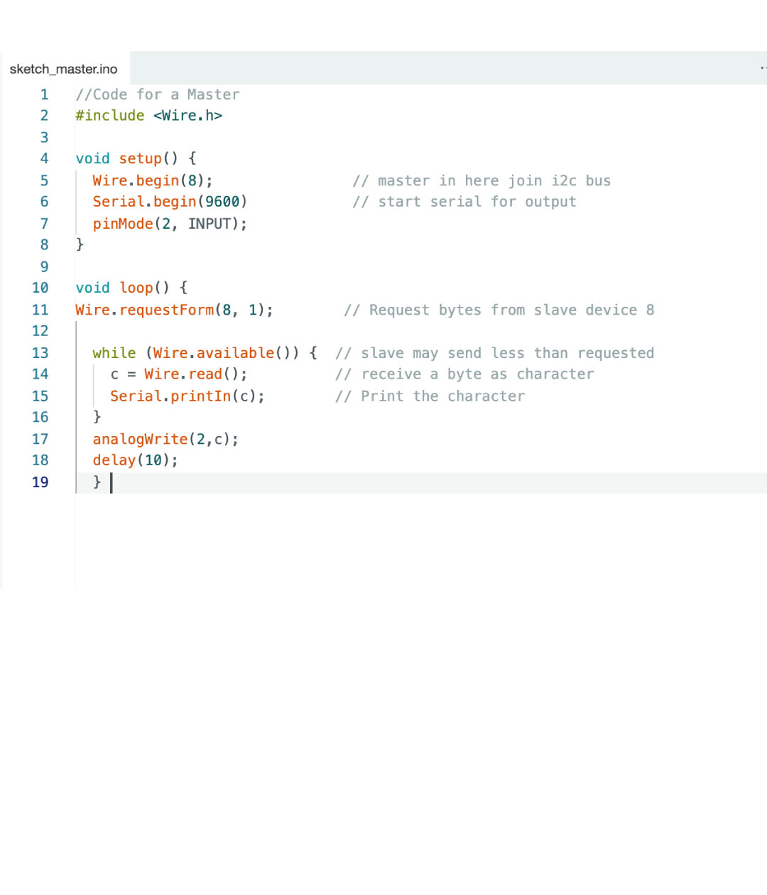
For the master code it needs to start with: "#include"this means to add the wire library for I2C communication.
Then in the setup(), it says the barduino to start on, then with wire.begin at 8 and for serial communication the baud rate(rate at which data is sent) of 9600, lastly, writing what is the pin output (in my case 2)
In loop(), its requesting to the slave device with the adress 8 asking for 1 byte of data. so it checks if there is data from the slave, if the answer is yes, then it reads it and stores it in "C" then using the serial monitor it prints it. Then, with analgWrite we set up the output on pin2 and a 10 delay before it repeats the loop.
Slave:
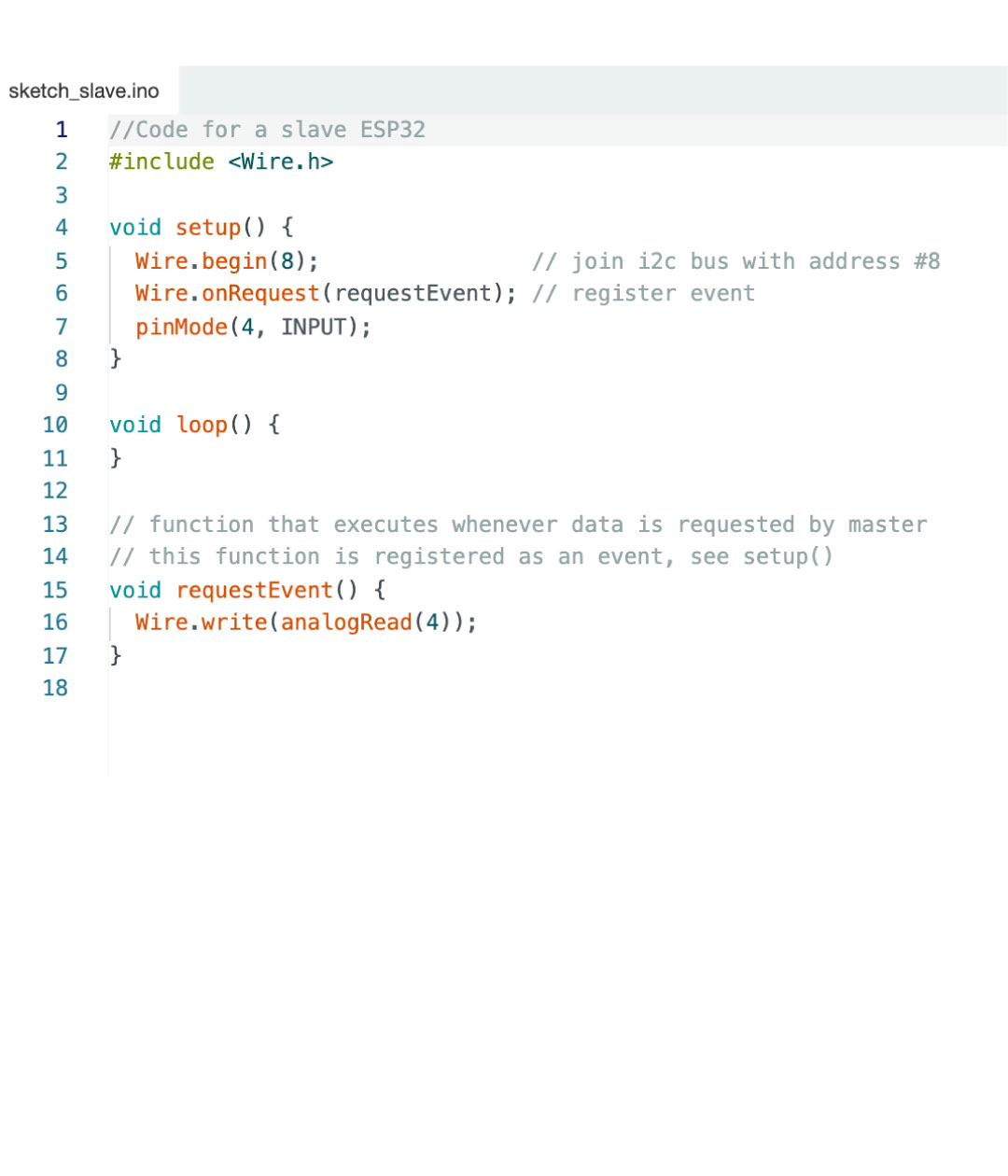
For the slave code, i'm using the ESP32 in my board so it needs to responde to the I2C master by sending the analogue reading from pin4. It also needs to start with the "#include" for the library
Then in the setup(), after start the communication as a slave, it reads the adress 8 (in the channel that they are communicating with wire.begin). Then it handles with the event whenever the master request data from this board. Lastly, the pin also needs to be in 4.
In loop(), the slave ESP32 is waiting for requests from the master and doesn't need to loop any task.
In the second test, I used my board as a master where it reads through the photoresistor the amount of light(my input) in the enviroment and then, the led on the barduino board as the output, where it lights up everytime there is a higher reading. This was the first approach for my final project that then I will used for the 22 LEDs.
//Code for a Master
#include < Wire.h >//without spacing

void setup() {
Wire.begin(8);                // master in here join i2c bus
Serial.begin(9600)            // start serial for output
pinMode(2, INPUT);
}

void loop() {
Wire.requestForm(8, 1);        // Request bytes from slave device 8

while (Wire.available()) {  // slave may send less than requested
c = Wire.read();          // receive a byte as character
Serial.printIn(c);        // Print the character
}
analogWrite(2,c);
delay(10);
}
//Code for a slave ESP32
#include < Wire.h >//without spacing

void setup() {
Wire.begin(8);                // join i2c bus with address #8
Serial.begin(9600)            // register event
pinMode(4, INPUT);
}

void loop() {

	//  function that executes whenever data is requested by master
	//  this function is registered as an event, see setup()

	void requestEvent() {
	Wire.write(analogRead(4));
}