This week we learn about output as being a hardware that displays or shows data from a computer or other electronic device. We work with LEDs, motors and sound.
As we learn few weeks ago, electricity is the flow of electrons or electric charge through a conductor. Then, the electrical charge is what allows an objects to attract or repel each other through electromagnetic forces, while voltage is the measure of the electrical potential difference between two points in an electrical circuit. The movement of charges through a conductor creates an electric current, which in turn produces a voltage difference.
Here is when the Ohm's law start to play a rol, V= I x R, it means that when the resistance is high, there is almost no current. When the resistant is almost 0, the current can be very large, leading to what we call a short.
Outputs:
Actuators are electronic devices that can be manipulated to convert electrical energy into various forms of useful output such as motion, light or sound.
Electromagnetism:
Is the relationship between moving charges and magnetic fields. When an electric current flows through a wire, it creates a magnetic field around the wire. This is the reason why we can use electricity to create magnetic fields, and why we can use magnets to generate electricity. This phenomenon is used in many everyday devices, such as electric motors, generators, and speakers.
Motors
A motor is a device that converts electrical energy into mechanical energy, (motion or rotation). It works by using the interaction between an electric current and a magnetic field to generate a force that causes the motor to rotate. Some examples are:
DC motors: Operate on direct current and are often used in small appliances
AC motors: Run on alternating current and are commonly used in larger machines and equipment.
Stepper motors: Are often used in precision applications that require precise control of motion.
Mosfet
Is often use in electronics to switch and amplify electronic signals. It works as a digital switch operated by a voltage variation, allowing very fast activations
Electroluminescence
When an electric current is applied to certain materials, such as semiconductors or phosphors, it causes the material to emit light. Such as light-emitting diodes (LEDs) they are semiconductor devices that emit light when an electric current is passed through them. In here we need to consider using Charlieplexing, a technique used to control multiple LEDs using fewer pins on a microcontroller, by carefully controlling the direction of the current flow.
Piezoelectric
Is a device that has the ability of to generate an electric charge in response to mechanical stress, such as pressure or vibration. When pressure or vibration is applied, the crystal structure of the material deforms, causing a separation of positive and negative charges, which generates an electric potential across the material. For example, in microphones, where they convert sound waves into electrical signals, and in ultrasound machines, where they generate and detect high-frequency sound waves. They are also used in sensors, such as accelerometers and pressure sensors, where they convert mechanical forces into electrical signals.
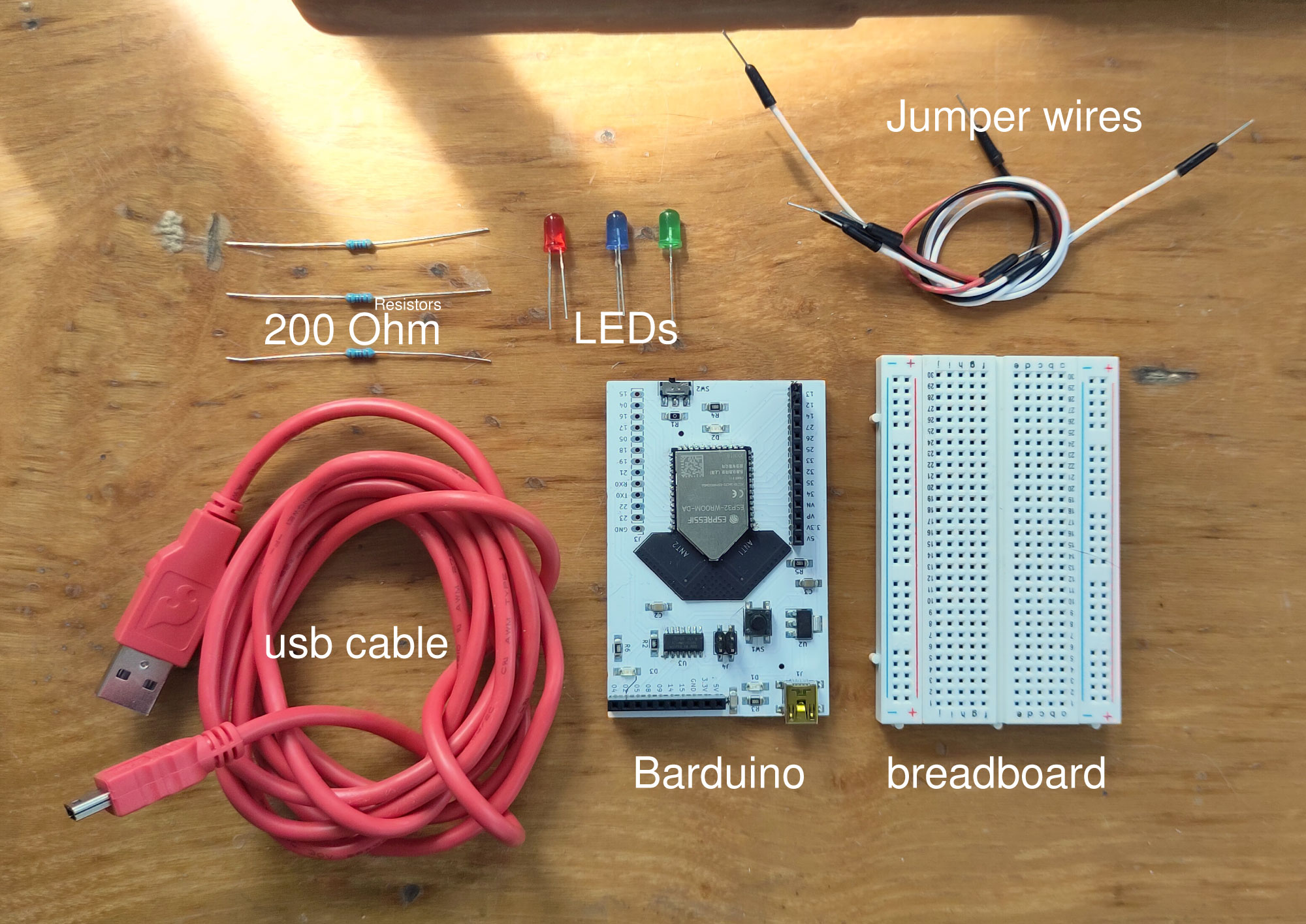
I used barduino for the prototype and for my final project developed new ones to test different leds with arduino.
Test
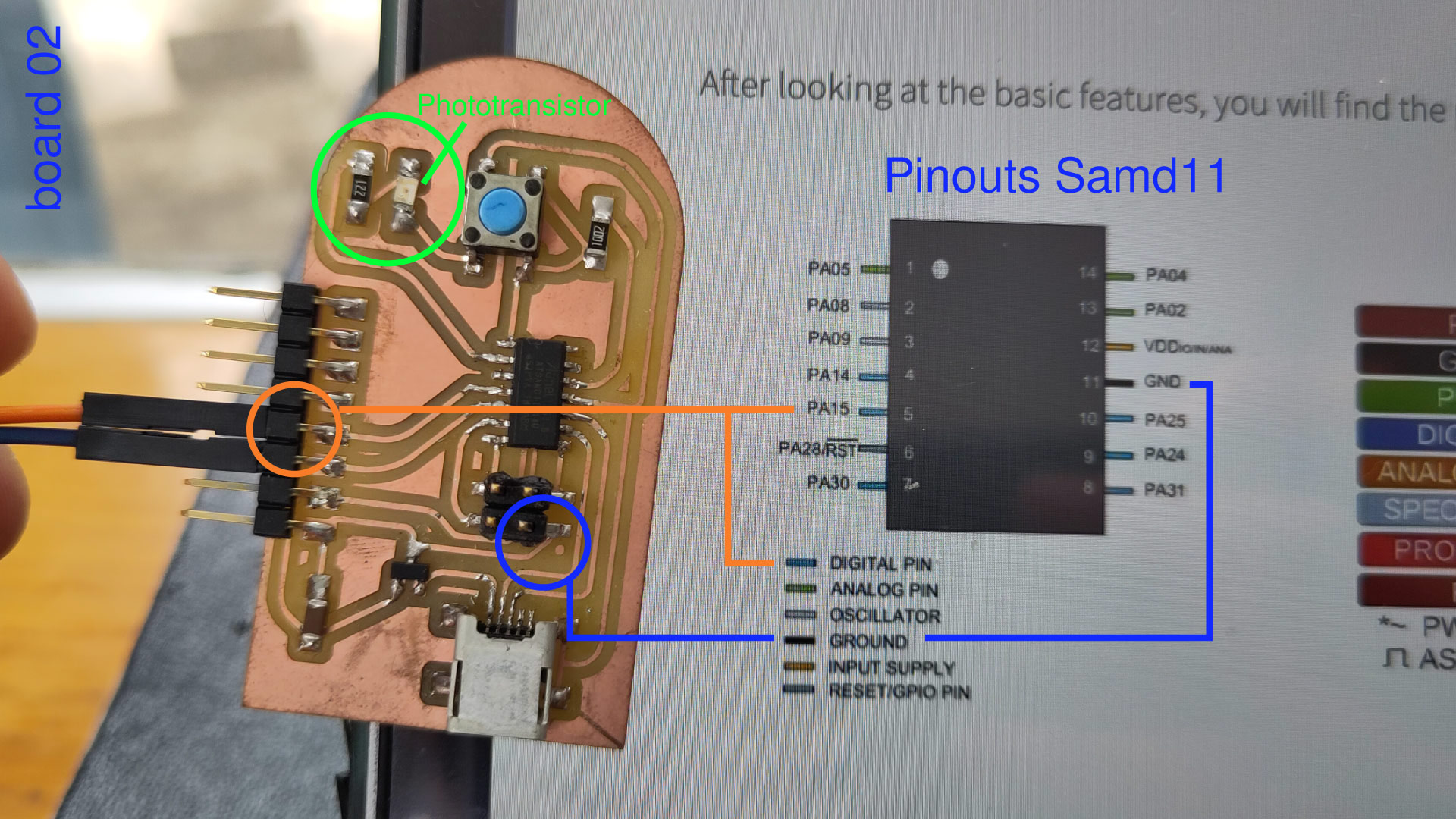
For the output test, I'm using the pcbboard created and using an example in the arduino library, FADE, the first step was to check the pinouts of the SAMD11 to know where to connect the pin of the led, also, the small dot (in blue)on the image is the ground from my board, this would be the pinout for ground.
Then in the breadboard only connecting a resistor to the negative leg of the led (shorter) and the longer to the pinout in my case 14, through a jumper cable. Then, a cable from the other leg of the resistor (220ohms) to ground.
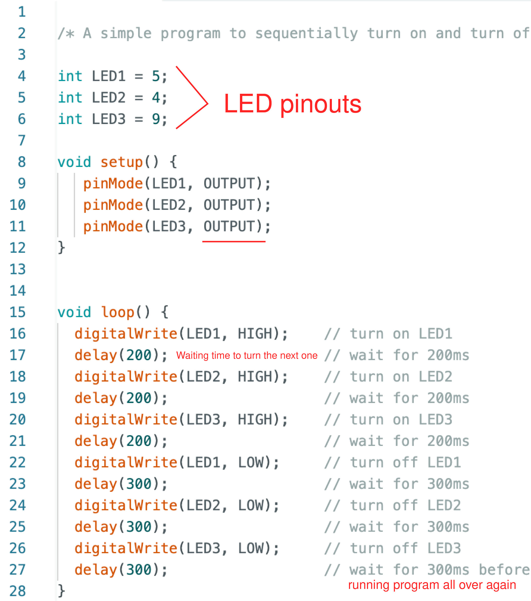
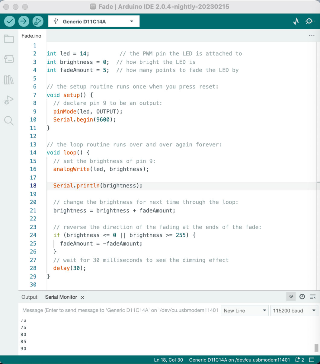
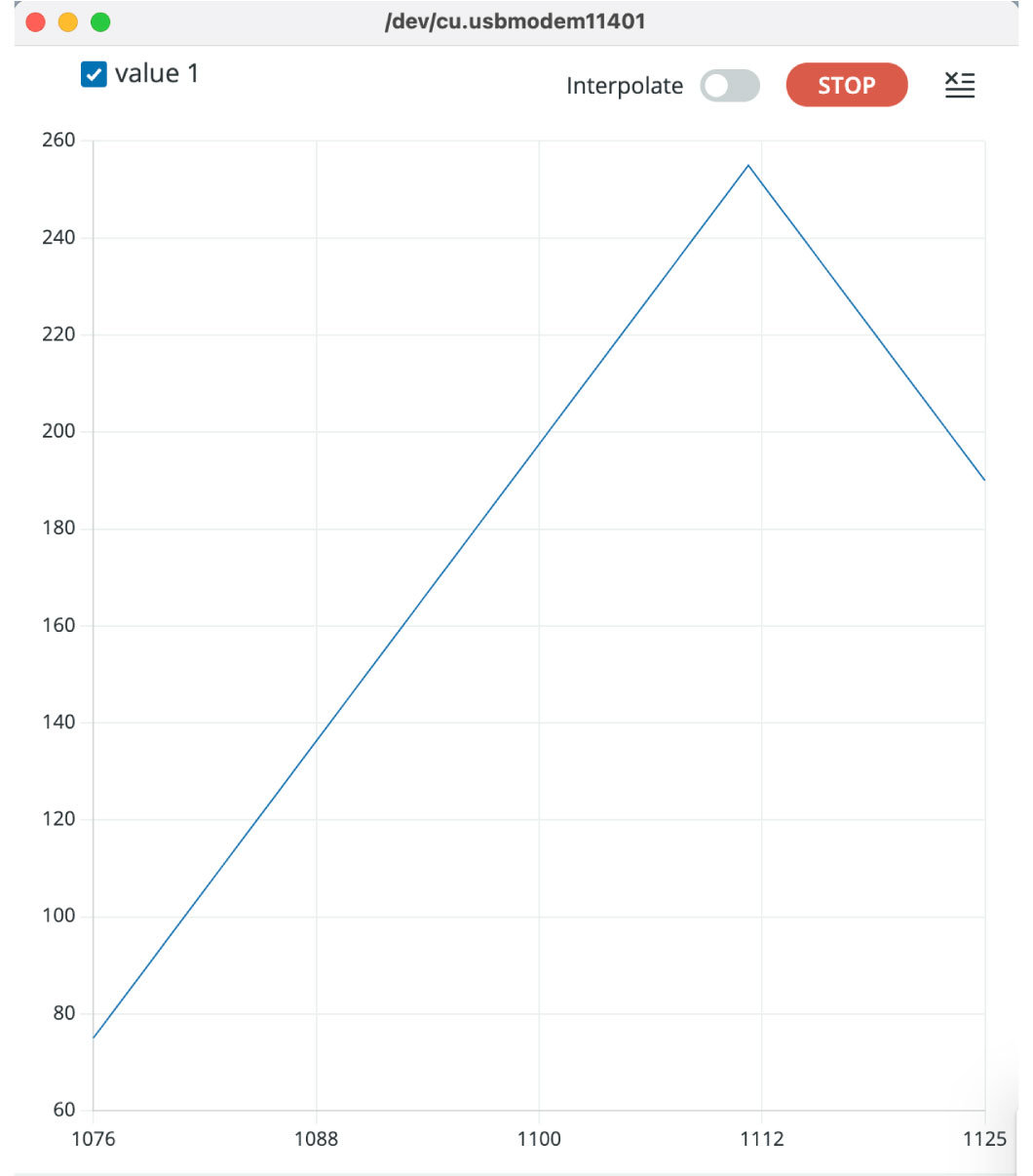
Next step, open the arduino library and select the example Fade, in here I just change the number of the pin, in void setup writting Serial.begin to 9600 as the baud rate and lastly, in the void loop with the command Serial.println(brightness) so in the serial monitor I could start seeing the number of the brightness.
Arduino its caps sensitive so I had to correct it multiply times and always remember to close with ";" after every line that finished.
int led = 14;         // the PWM pin the LED is attached to
int brightness = 0;  // how bright the LED is
int fadeAmount = 5;  // how many points to fade the LED by

// the setup routine runs once when you press reset:
void setup() {
  // declare pin 9 to be an output:
  pinMode(led, OUTPUT);
  Serial.begin(9600)
}

// the loop routine runs over and over again forever:
void loop() {
  // set the brightness of pin 9:
  analogWrite(led, brightness);

  Serial.println(brightness)

  // change the brightness for next time through the loop:
  brightness = brightness + fadeAmount;

  // reverse the direction of the fading at the ends of the fade:
  if (brightness <= 0 || brightness >= 255) {
    fadeAmount = -fadeAmount;
  }
  // wait for 30 milliseconds to see the dimming effect
  delay(30);
}
Final project
For my final projects, I used LEDs as outputs, this because I need measurable response to the input or environmental conditions of amount of light in the enviroment.
In my final project, I've chosen to use Light Emitting Diodes (LEDs) as output devices, which are a specific type of electronic component known for emitting light when an electrical current passes through them. In this role, the LEDs will serve as visual indicators that respond to changes in the surrounding light conditions, thereby allowing to receive clear and instant feedback about variations in ambient illumination. So what I did was connected from the SAMD11 the pinout 13(digital) to one leg of the LED and the other one first to the resistor, then to ground, in this case on the breadboard there was not a phototransistor because I already added to the board itself.
Buzzer exercise
Another test for this week assigment was to use a buzzer as an output using one of my pcb boards, it was an 8-bit, this music is composed using a limited set of sound channels.
A buzzer is an electronic component that produces sound when an electric current passes through it. It works by creating a sounds by controlling the frequency and duration of the electric pulses that it receives. It is an output because it produces soundfeedback based on the instructions received from the microcontroller in my board.
Set up:
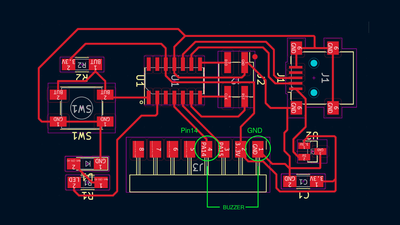
So I solder a buzzer to the digital pin out 14 the possitive leg and the other one to ground, then connected my board to the computer and checked in arduino that the port was connected and my board as well, finally uploaded this code, that is to the pin 14 (buzzer) It has an array of 8 notes and duration for each one is the same 4:
#include "pitches.h"

int pin = 14;


// notes in the melody:
int melody[] = {
  NOTE_C7, NOTE_A6, NOTE_G6, NOTE_F6,
  NOTE_E6, NOTE_D6, NOTE_C6, NOTE_G5
};

// note durations: 4 = quarter note, 8 = eighth note, etc.:
int noteDurations[] = {
  4, 4, 4, 4, 4, 4, 4, 4
};

void setup() {
  // iterate over the notes of the melody:
  for (int thisNote = 0; thisNote < 8; thisNote++) {

    // to calculate the note duration, take one second divided by the note type.
    //e.g. quarter note = 1000 / 4, eighth note = 1000/8, etc.
    int noteDuration = 1000 / noteDurations[thisNote];
    tone(pin, melody[thisNote], noteDuration);

    // to distinguish the notes, set a minimum time between them.
    // the note's duration + 30% seems to work well:
    int pauseBetweenNotes = noteDuration * 1.30;
    delay(pauseBetweenNotes);
    // stop the tone playing:
    noTone(pin);
  }
}

void loop() {
  // no need to repeat the melody.
  for (int thisNote = 0; thisNote < 8; thisNote++) {

    // to calculate the note duration, take one second divided by the note type.
    //e.g. quarter note = 1000 / 4, eighth note = 1000/8, etc.
    int noteDuration = 1000 / noteDurations[thisNote];
    tone(pin, melody[thisNote], noteDuration);

    // to distinguish the notes, set a minimum time between them.
    // the note's duration + 30% seems to work well:
    int pauseBetweenNotes = noteDuration * 1.30;
    delay(pauseBetweenNotes);
    // stop the tone playing:
    noTone(pin);
  }
}
The last step was to upload the code and executed.
Things to learn
01 check always on Arduino the connected board
02 Restart barduino with button every single time
03 Write over image the components used not to forget and the steps
04 Change a lot the numbers and delays to understand what is happening.