Introduction
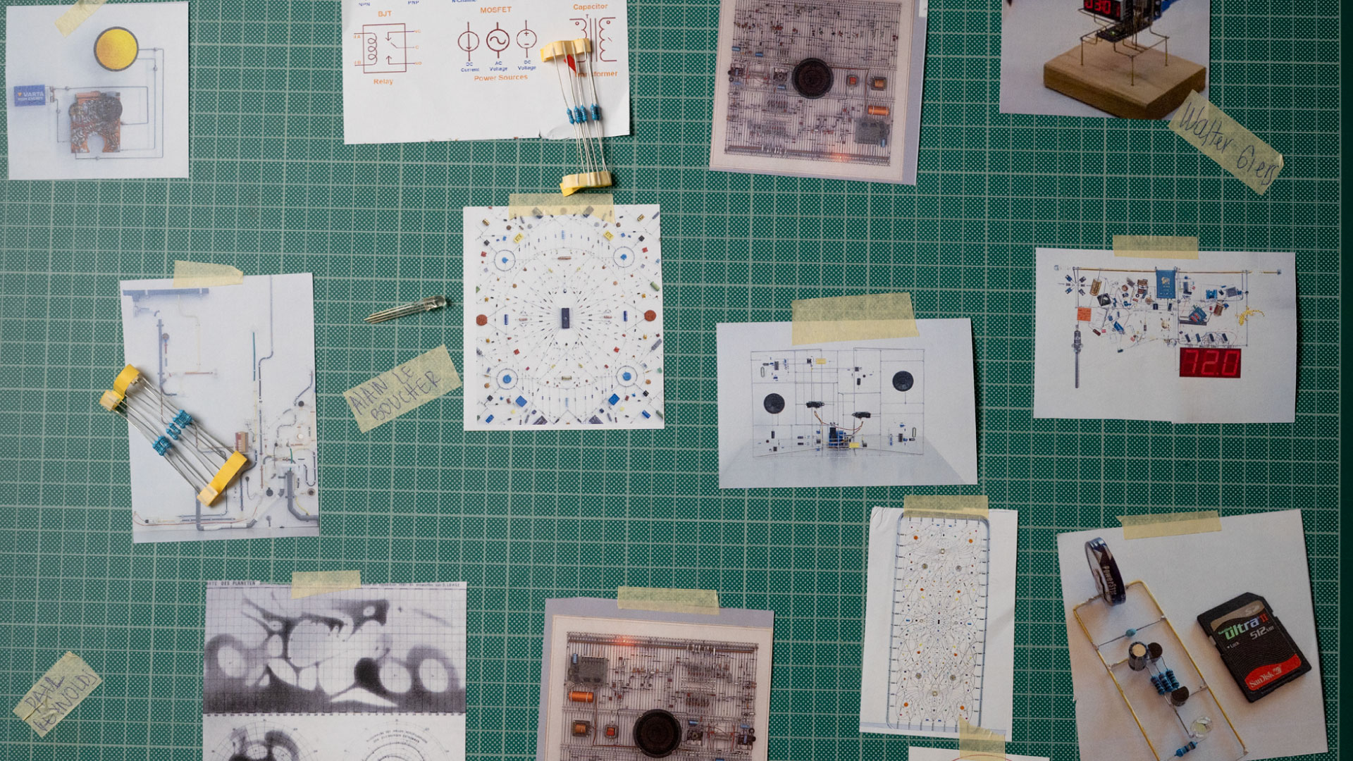
Ever since I started Fab Academy, I could sense always the idea of one or the other, Yes-no, High-low, 0-1, ground-5v and so on. But the way I understood it was that one is a part on the other. My first approach was to question how can I translate this into my final project, and if it could be added the artisanal process as an objective of the scope. Then, I got inspire first, from the abstract work of Paul Reynolds and the electronic design week, how beautiful the pcboards could be and how all of the components have potential to be display from their symbols to the connections. Lastly, I got my primary source of inspiration, starting with the sculptures of Mohair Bhoite, I started to learn about freeform electronics and at that point everything made sense. ( There where other artists as well, such as Alain Le Boucher, Peter Vogel and Walter Giers.
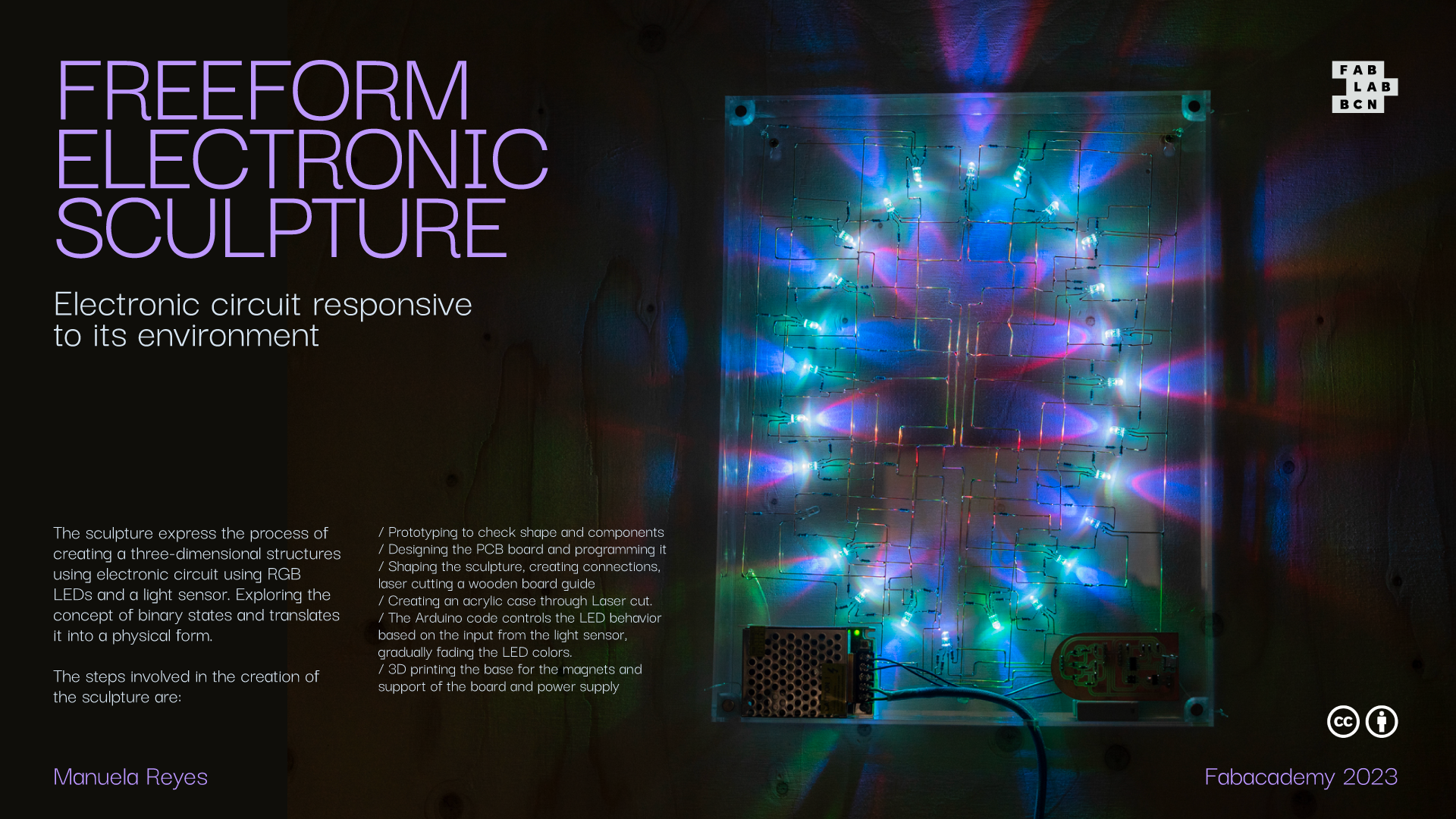
So I wanted to build an electronic circuit with a simple function than can grow from having more boards, more information and ramifications. My sculpture has RGB leds connected in parallel, that will turn on when the light sensor ( phototransistor ) sense small amount of brightness in the environment. Once the light is off, the leds will turn on, revealing a simple pattern.
Steps
I will enlist them as how my experience recommended to go, instead of the process that I follow, at the end of the production I realise things could be more efficient in the follow order:
1. Prototype:
Taking only two RGB Leds, adding to each one its resistor and making the connection on a breadboard with an existing pboard, to test angles, get used to soldering on air and check if all of the connections are stable. Be super careful not to make the soldering tubes touch each other. Note: Each LED colour needs a different resistor, in my case for green and blue a 220ohms worked well and for the red 330ohms.
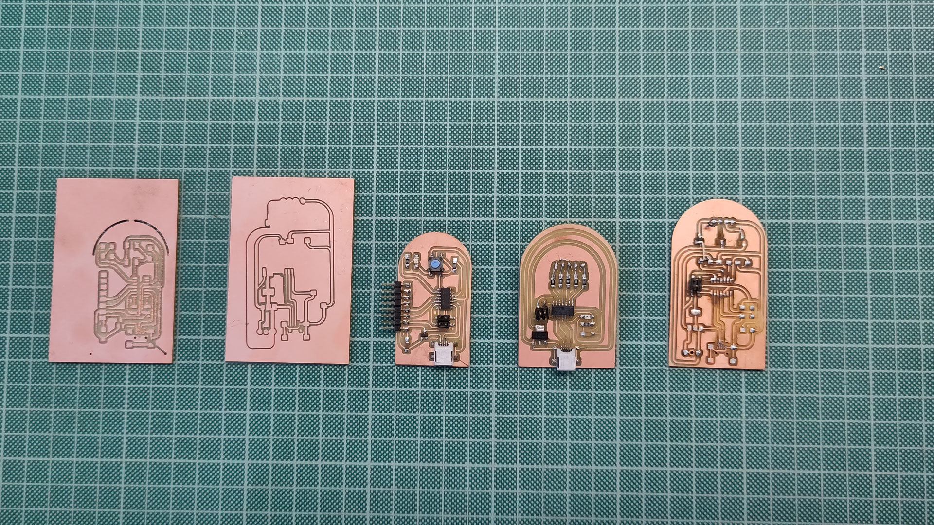
2. PCB board:
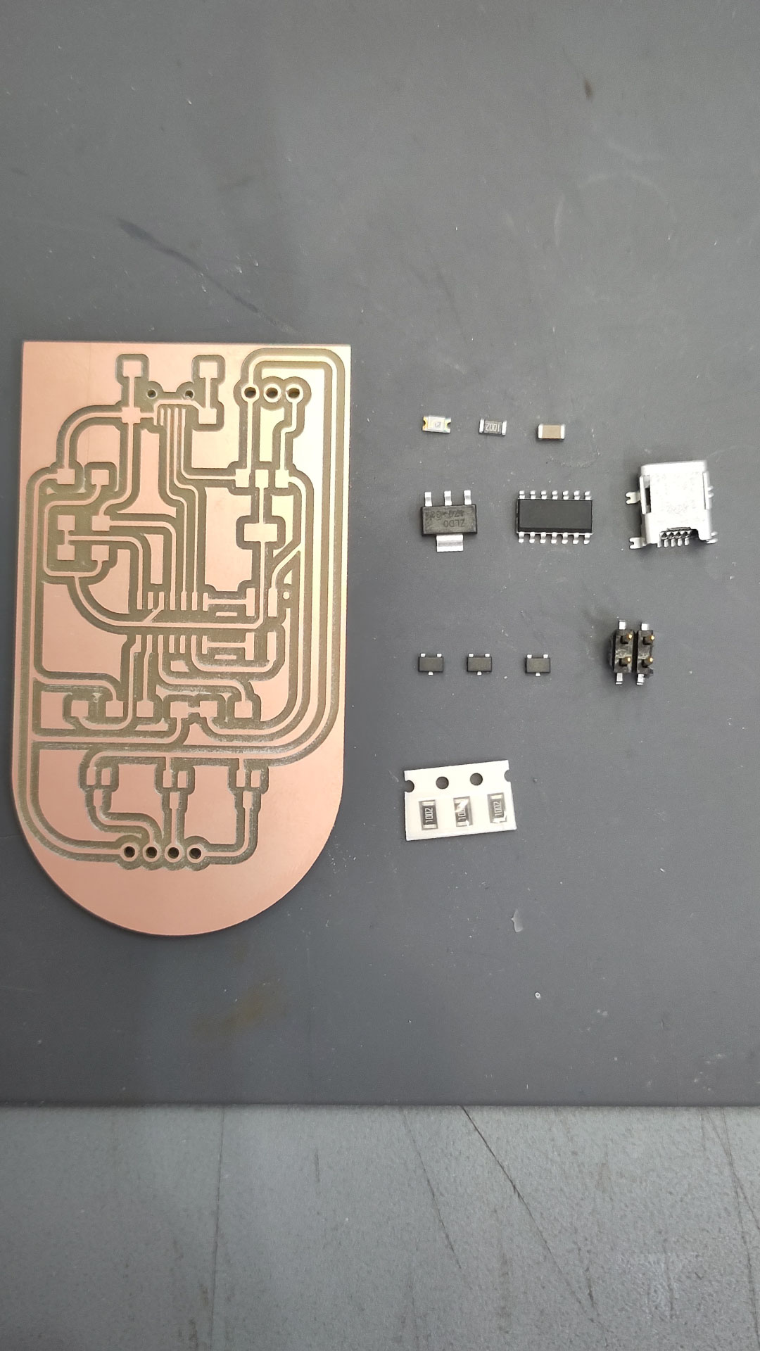
After 4 boards I got the right one, the component used in this one were:
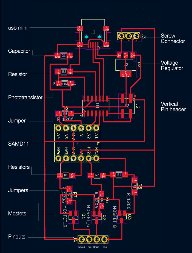
Power:
Sensor:
Level convertor:
Pinhead & Mosfet:
Jumper resistors:
Here is the kicad version, all the lines are made in 90º angle and then I edit them on illustrator to choose an equal radius to all of the lines. The jumper resistors are used to create a bridge between: Level 4 to Pin Red in the level convertor and in each colour between the photoresist and the mosfet pinhead.
The production of the board was the same as the past weeks, exporting three files in png for the holes, the outlines and the traces. Then using mods to create the file for the cnc. I used two different end mills: 1/64 for traces and 1/32 for the holes and outlines. It took less than one hour to generate the whole board. Then choosing the list of components from the lab drawers and soldering.
3. Program the board
Once everything is solder and tested with the multimeter for continuity, then is the time to program it. Using the boot loader we created in the previous weeks, it needs to be connected booth boards to the computer, open the terminal, check for folder edbg that I download previously, and run the sam_ba folder. In case that this doesn’t work, inside of Arduino we can run the board without the boatload, going to view in the toolbar choosing “CMSIS-DAP” and then, the option below “Burn boatloader”. (This last option worked for my final board, even that the others before this one, were programmed by the terminal and edbg)
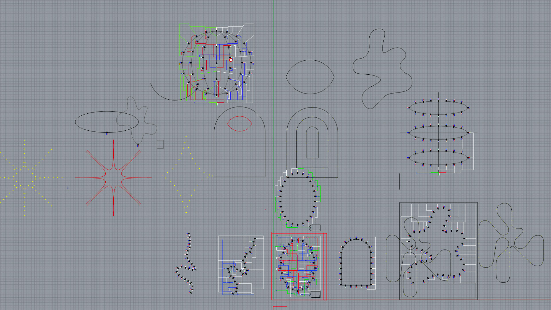
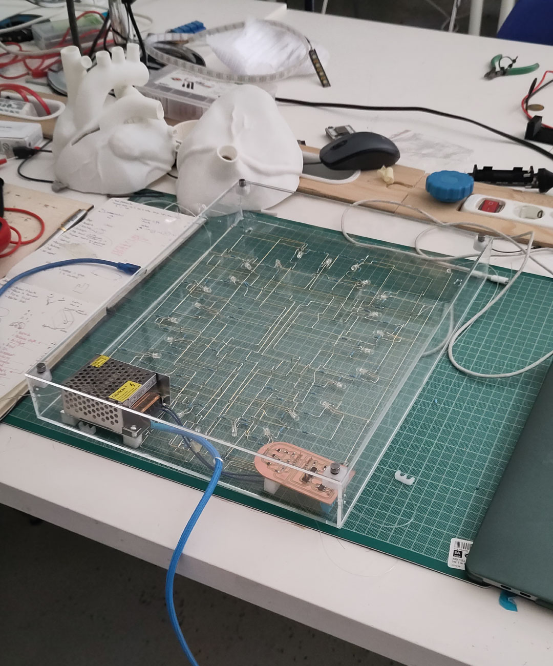
4. Exploration of shape
Now, is the time to create the sculpture, I measure with a calipher an RGB Led and resistor to have the closest possible size and then create them on rhino, once I had them, I start playing with lines and using command array on curve for displaying the LEDs along the curve, I started with sacred geometry and complicated shapes, then too organic and end up simplifying it to an oval using 26 LEDs in total. There is always the possibility to enlarge it but considering that each bulb needs three resistor is more than 78.
Once the LEDs have their final position I started to imagine the general size of the sculpture, (410x320) then choosing that my pcboard would be display on the lower right corner of the sculpture and the power supply on the lower left corner. Then, starting to create the connections between the ground from the board to each one of the ground legs (longest leg) in the LEDs. I wanted to have some symmetry, so all of the lines were mirrored and connected with the green line then in this one adding a resistor per LED. Then I did the same for the blue and red, mirroring half of the lines to have an imaginative grid to follow.
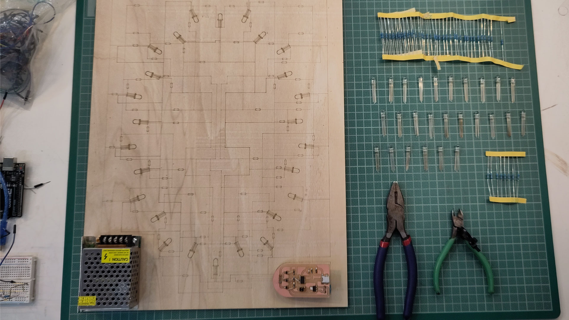
5. Wooden board guide
Once I was happy with the general look of the connections, I exported to Illustrator using first make 2d command, and then cleaning and aligning some details (this step could be made directly on rhino but the look is easier on illustrator due to the flat background and choosing each point) then I divide the lines between LEDs, lines and outline. The last one to be cut, the LEDs raster with a faster speed so it would have more opacity than the lines. Then, I used the laser cut with 4mm mdf wood, the first test had a good look that gave me the general idea of the physical size. Then with colour markers I painted the resistors in Red, green, blue to know which line correspond to which led.
6. Assembly time !
Now is the part of the artisanal work. I used Multi Hole Brass Copper Tubes that we already had in the lad, this is the reference link.
First, have some cutting pliers and small needle nose pliers, this last ones kind of define the angle and thickness of the folds on the tubes, also I bought thin masking tape and had a lot of small pieces, this ones will hold the tubes on the mdf board.
So the first step was to bend, cut and tape all of the pieces in the ground line, I started with this one because without having the resistors would be the easiest, once all of the pieces where cut, I turn on the solder Iron and soldered them together. This last part, was faster than I thought, so really the time is bending and cutting. Because the tubes I used are hollow, when bending to 90º, most of them crack without breaking but as reinforcement, I added tin to the corners.
Then did the same with the red, green, blue lines, the only differences were: First, to add the resistors, in which I cut must of the metal leads because they are too thin and tent to bend). Second, that important to jumped and bridged all of the tubes where intersections of the cables were shown in the board. Lastly, adding the LEDs.
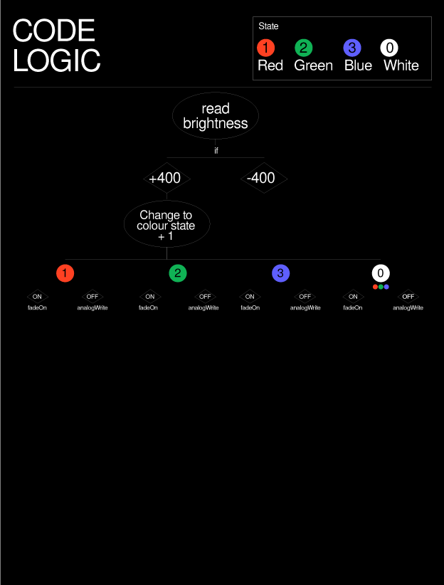
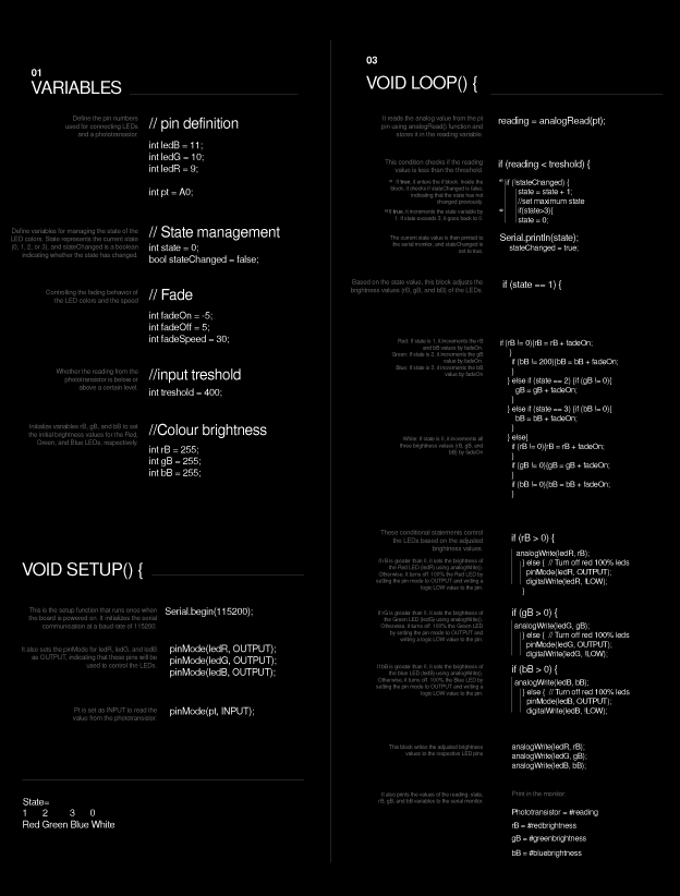
7. Arduino
This Arduino code controls the behaviour of an RGB LED based on input from a light sensor. The code defines the pin connections for the LED and the light sensor. It sets up the initial states and variables. In the main loop, it reads the sensor input and determines the LED color and brightness based on the input value and the current state. It gradually fades the LED colors on and off using the fadeOn and fadeOff variables. The code also includes serial communication for being able to read the value, the state and the colours.
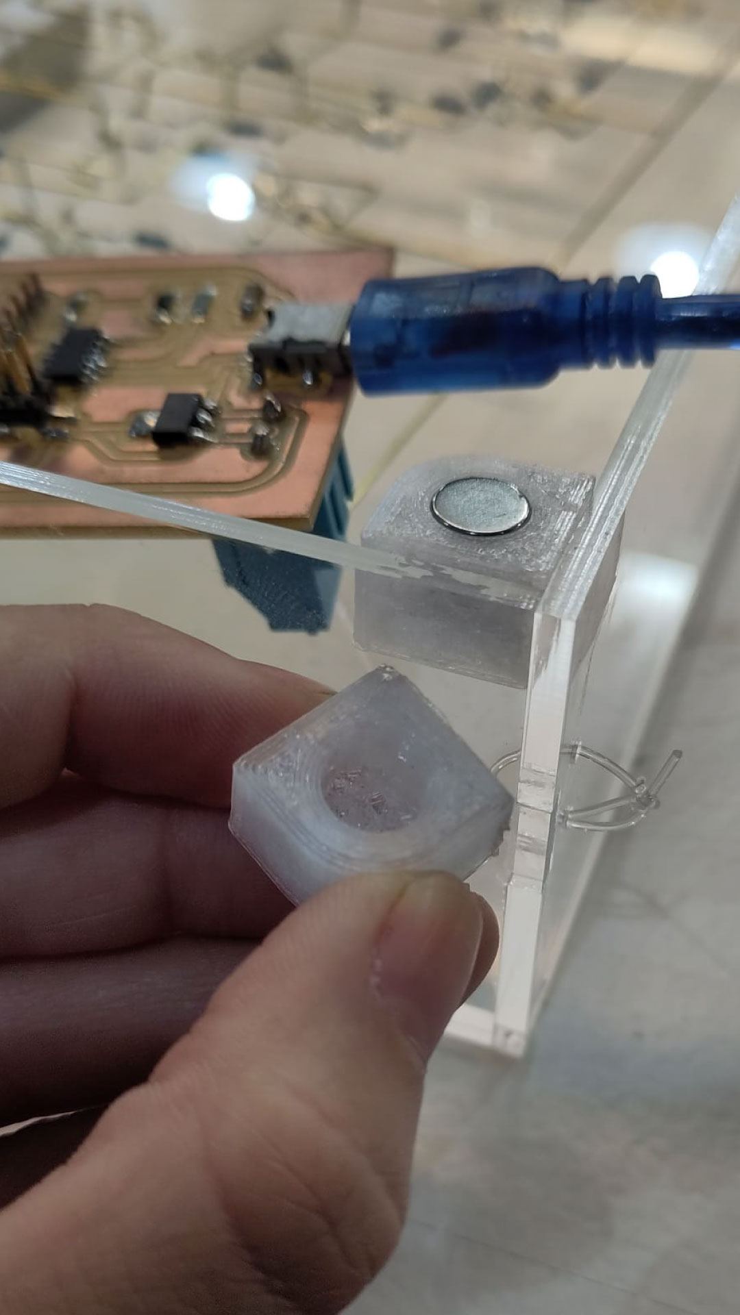
8. Case
For the general case, I wanted the sculpture to be suspended inside of an acrylic box that I can hang from my wall, for this one I designed it on rhino with 3mm acrylic and cut it with laser, for the assembly the joins where glued with a fastpace superglue for acrylics, then, I designed in rhino four small based to put magnets inside of the box and being able to close the cap with them, for this, they were printed in 3dprinter. Here is the file for the 3dprinted corners.