Week 07

Computer controlled machinning

This week was the coolest so far. Discovering the CNC, making prototypes on laser cut and then milling a big piece of plywood to create something and understand the machine.

  • Week 7th of feb to 14th of march
  • Keywords Endmill, climb, dogbone
  • Software Rhino, rhino cam plugin

01CNC

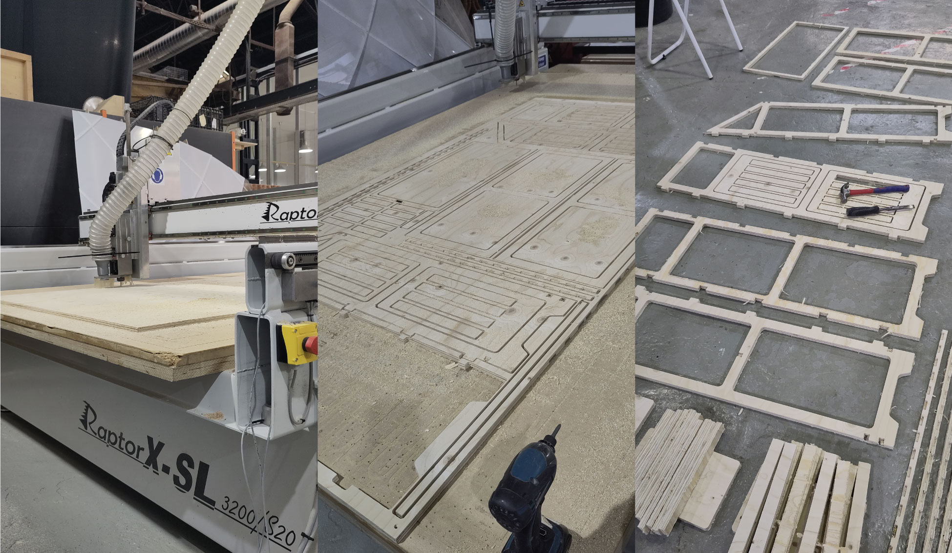
Is a terminology use for Control numerical control milling or cutting. This is part of a subtracting methodology, means to cut away with a type of drill, material from a big piece of material until getting the desired shape and model, 2.3 milling. This is wildly use worldwide because of the power and how easy is to use it to have a good quality.
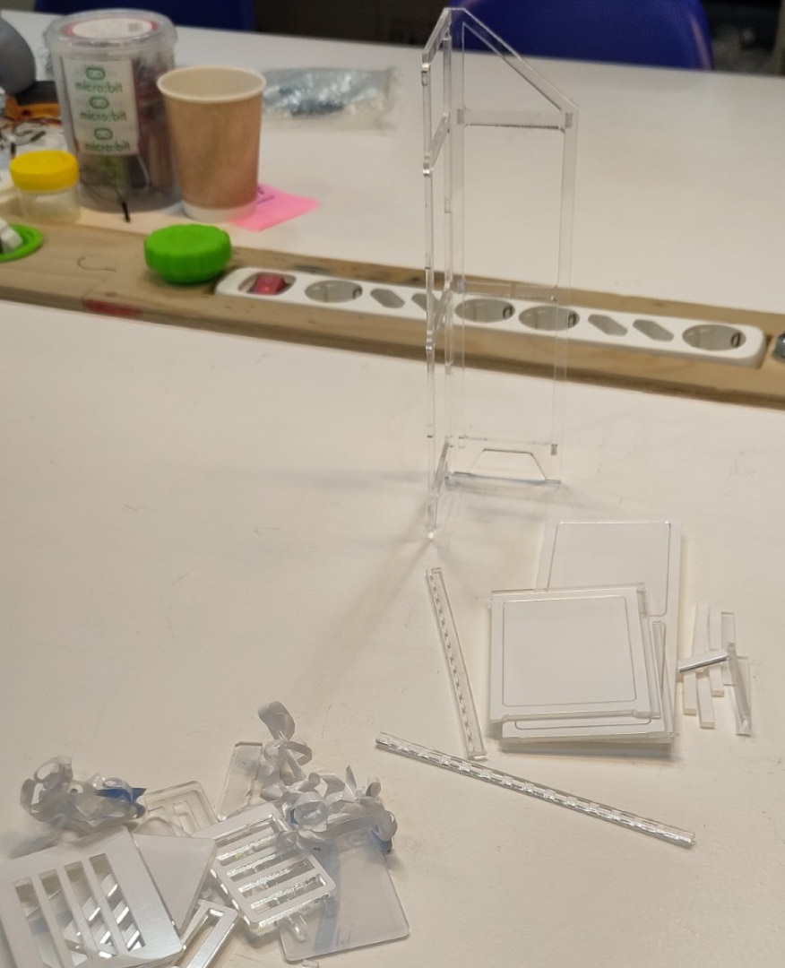
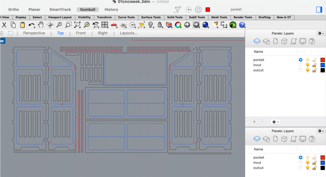
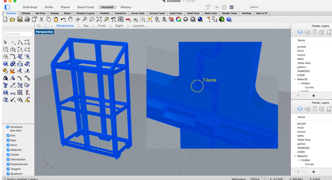
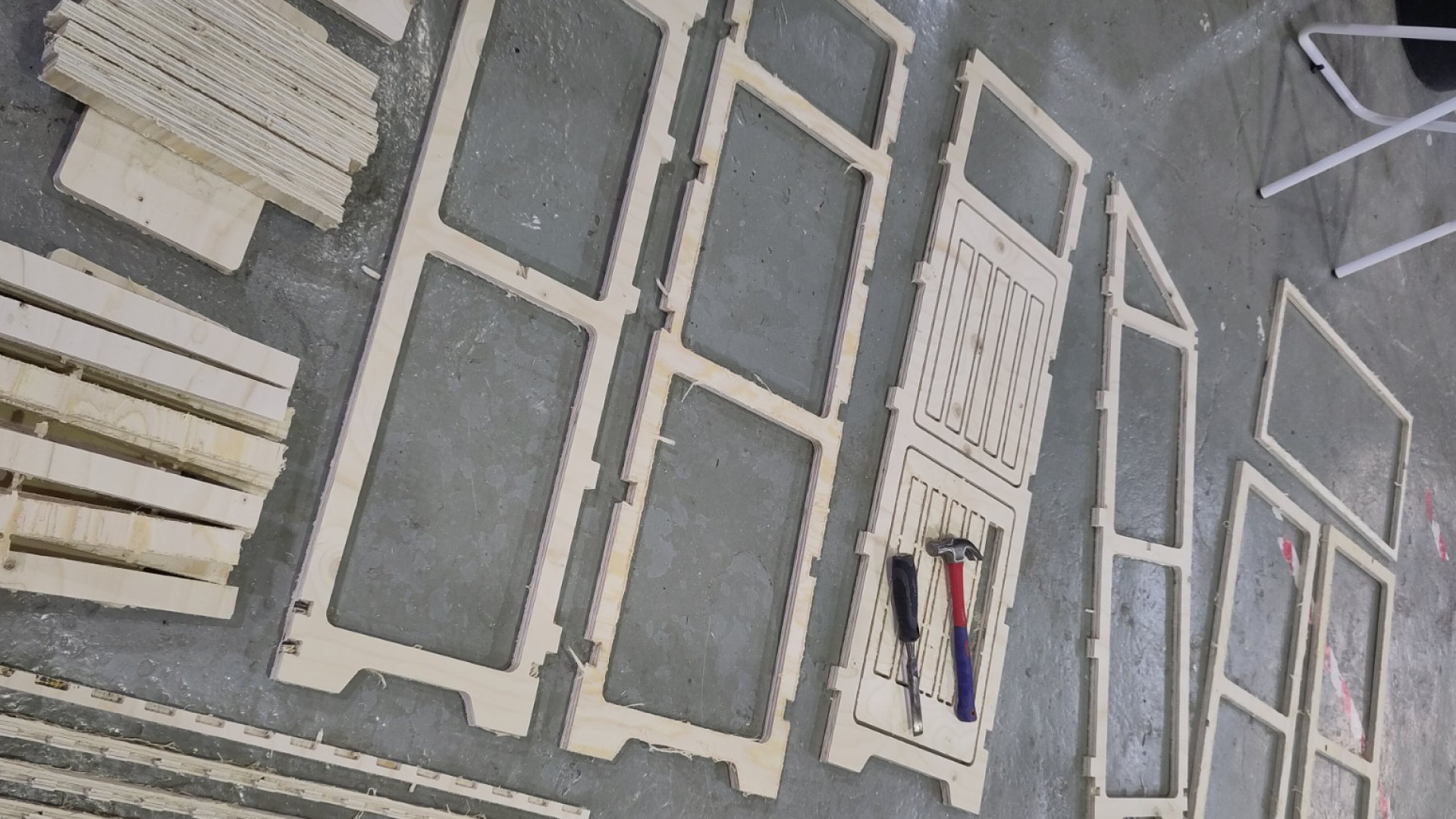
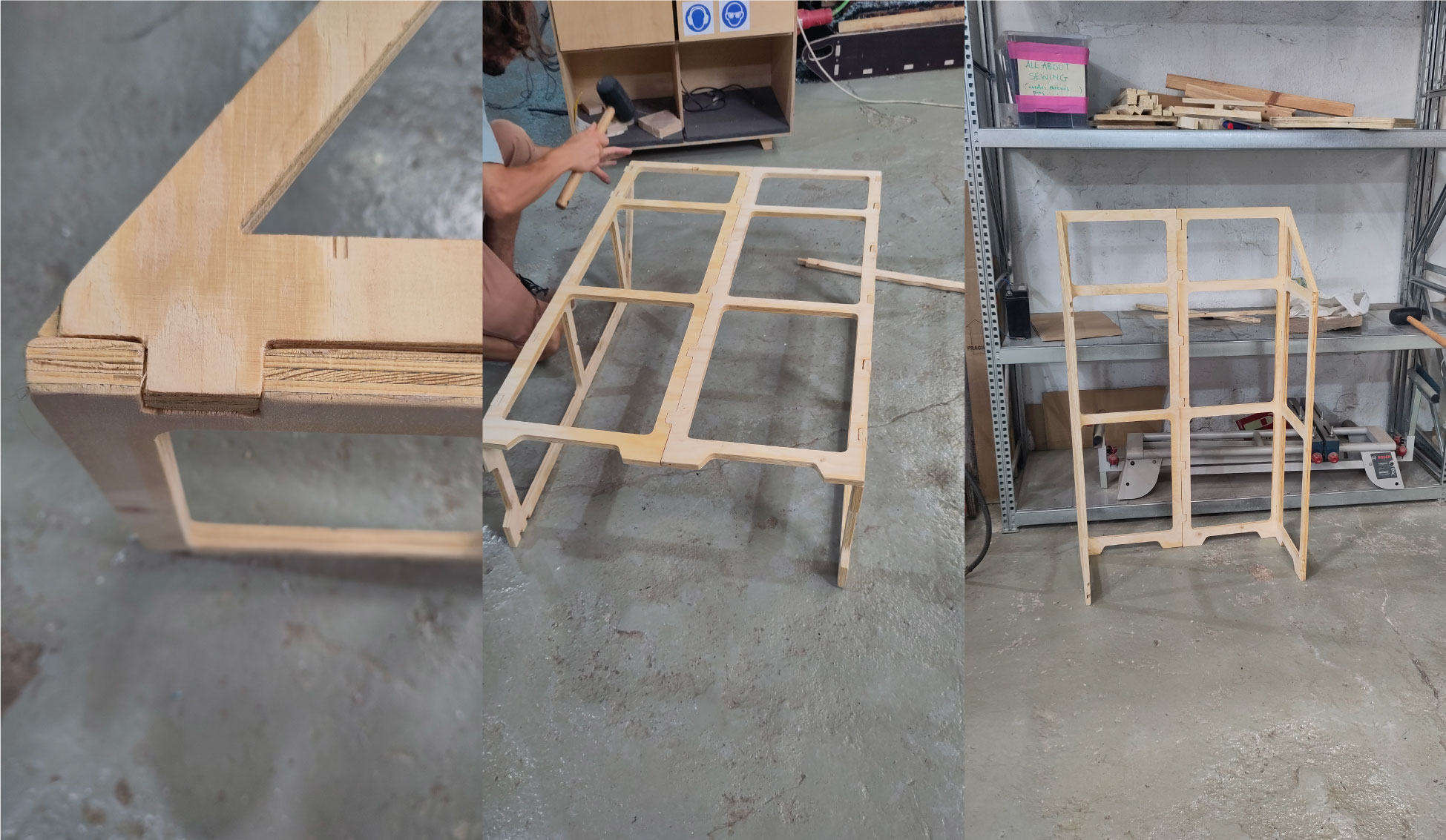
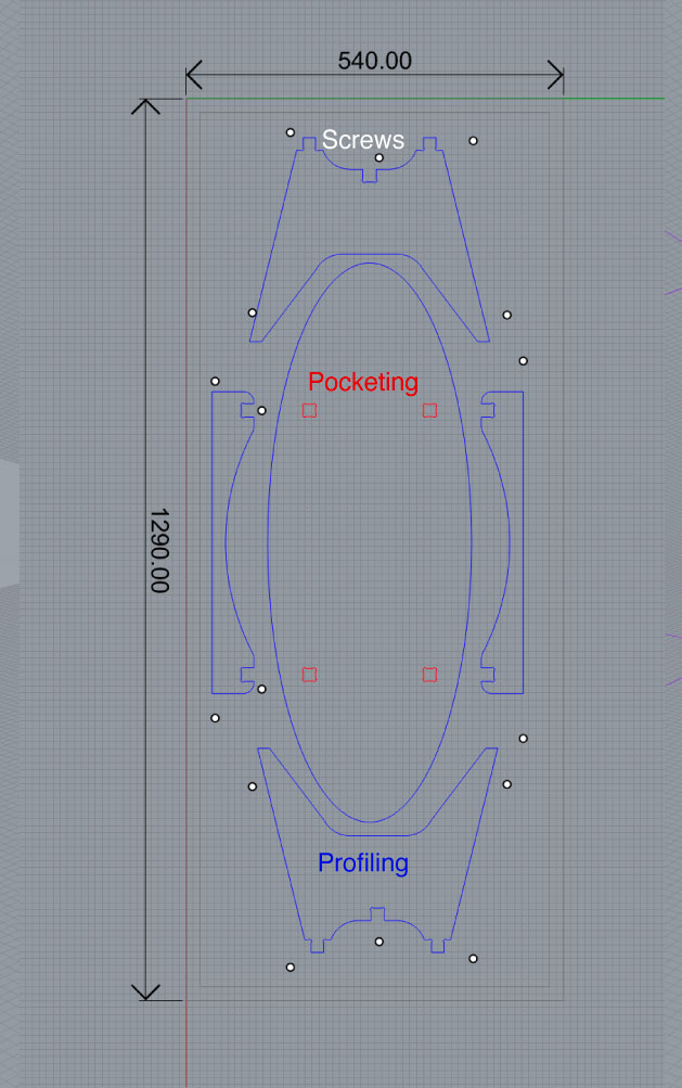
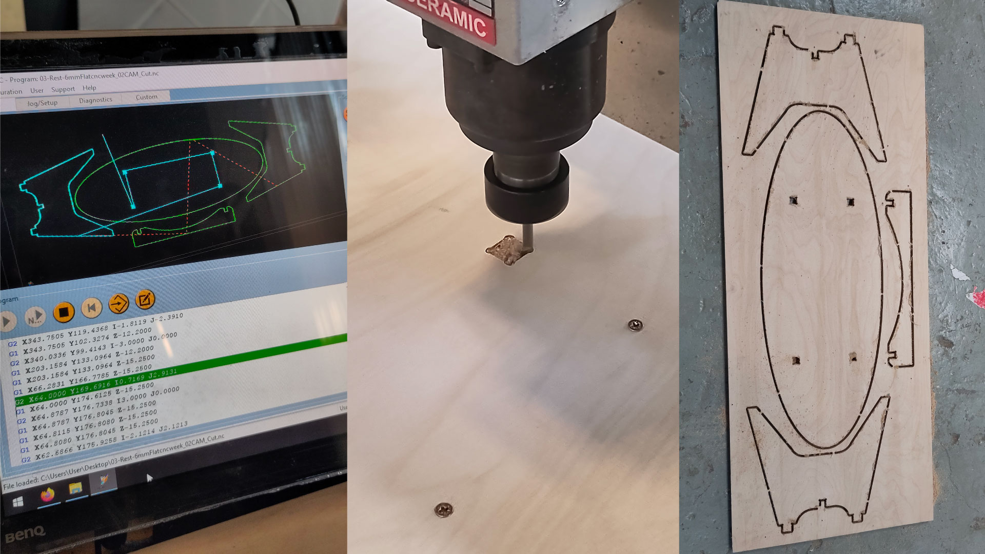
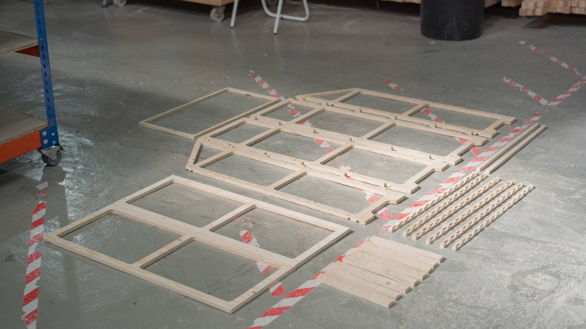
Two different procedures 2D cutting of parts and post assembly ( for example a guitar, first one side, turn it and the the other one).

Accuracy One of the biggest advantages to use the CNC is the consistency and accurate pieces. This means the repetition of each piece is almost the same ( 0.05 - 0.10 mm repeatability).
Flexibilitye Is a measure of the opposition to current flow in an electrical circuit. Resistance is measured in ohms.
Resistance It can replace amount of equipment and material from a traditional wood manufacturing this translate in low amount of energy spend, investment, footprint, less space, time of the procedure and automate a lot of the process.

Parts of CNC:

01 Slotted table Bed, aluminium profile with T shapes on the side, to clamp material on top.
02 Bridge Made out of steel or aluminium is the limiting factor of the total depth of the material ( 10mm less of the total material, 1/3 of the size)
03 Stepper This is the dc motor that controls at high speed the movement, rotating on how many steps is moving.
04 Spindle or router Is where the knife is attach too.
05 Router or spindle This are the motors different in price the horse power, smooth finishing like we have on the lab that is a spindle.
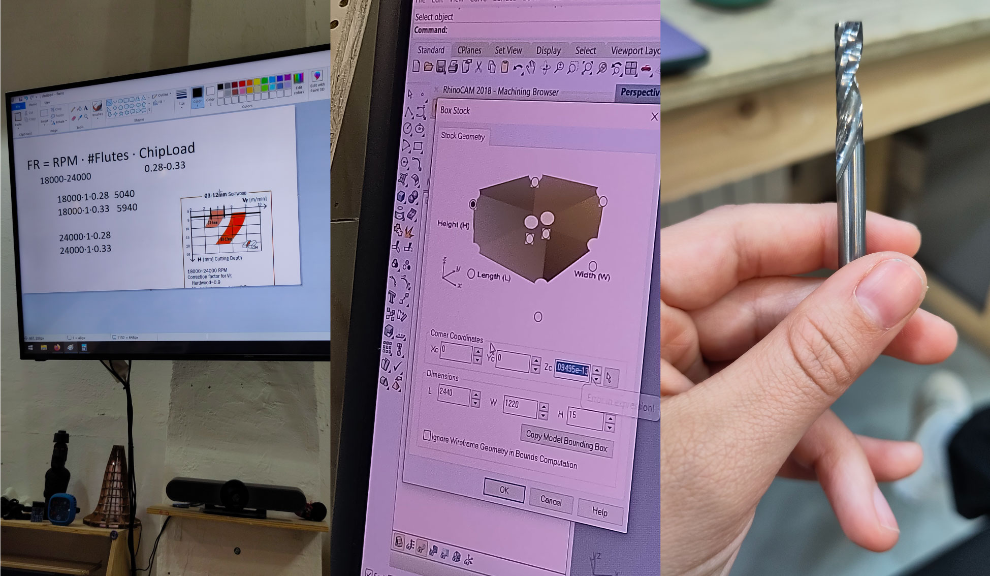
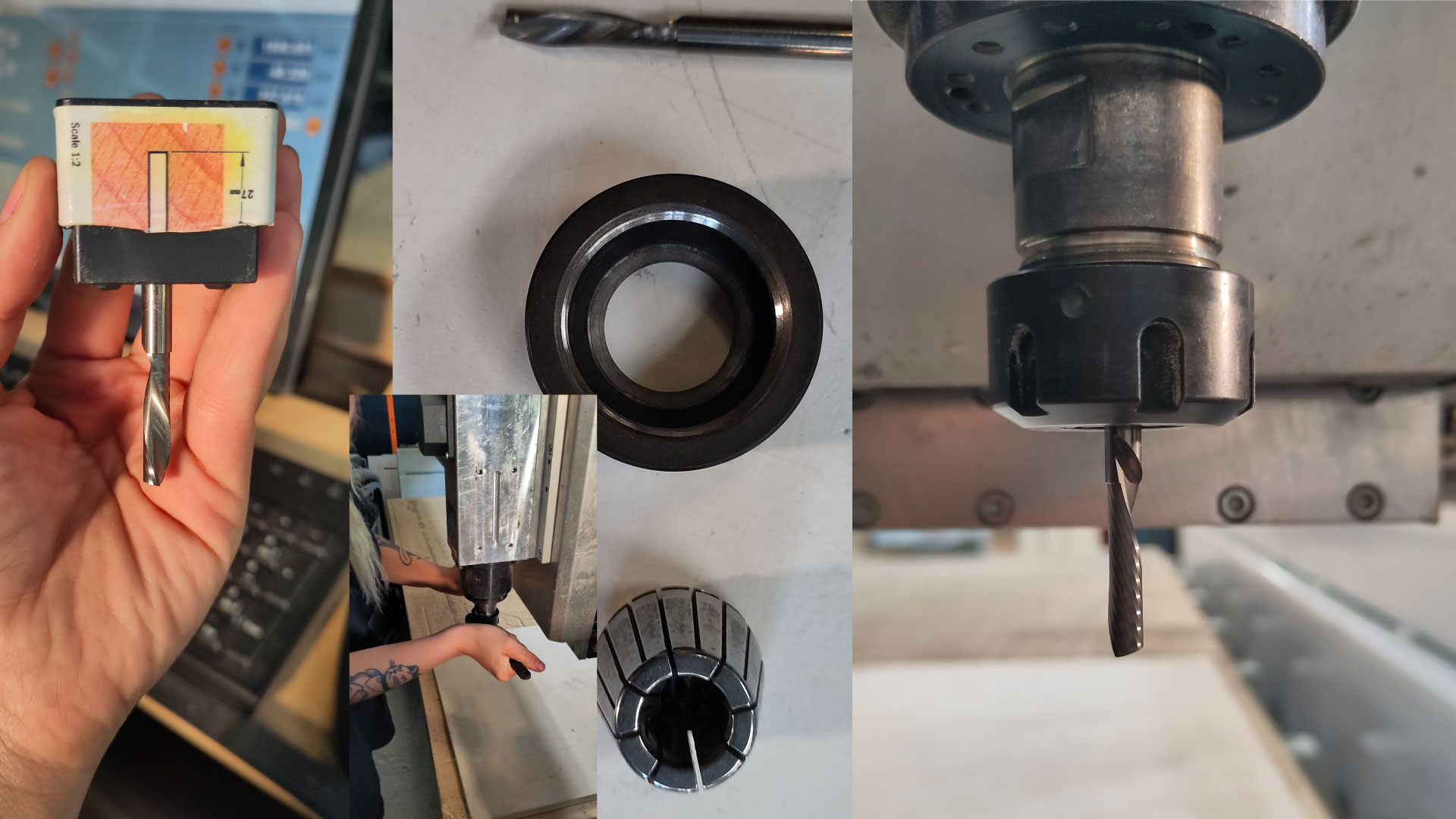
06 The collet: Clamping tool that holds the drill, or the held of the router.

02Exercise


For this week, is doing something big! So I had some references for a greenhouse balcony size for my plants. The first part was to sketch all the pieces and general shape that I can have in the space and also on the total of material given to use. Plywood 2440x1220x15mm, having this in mind and leaving an offset of 2mm I started to design the sides, and back of the greenhouse, having three levels. For the doors, wanted a simple two doors opened by hinges and one hatch for the top level. It has three levels, one for seedling, then the second one, for bigger plants, this one is half size and the last one with the space to grow more from the second level, all of them with a flooring as a deck with dilatation so if I water the top layer, the water can run until the floor.

I design it on rhino as a rough idea in 3D, when I was happy with the shape, then started adding more details on 2D and ideal measures. Once it was the end result that I expected, I extruded the curves with a thickness of 15mm, to check if building it made sense. It did not, for multiple times I had to fix the 2d, and consider pocketing, thickness…

Lasercut test. Before going big and cutting everything on the CNC, I scaled down the design to check the assembly process. First try with acrylic of 3mm ( which I didn’t tape correctly to the bed of the board and was so difficult to take of the pieces that I ended up breaking them) then try with plywood of 4mm which I had to scale it again from the big file. In this case, the side and back walls worked well, the doors as well, but the internal structure and the hatch was off completely. So I had to redo the editing.


03Rhinocam


Rhinocam opens up as a side menu inside of rhino, just by writing it as a command.

01 General Setup

Choose machine, post and box First writing the amount of axis to choose machine and in post is the post processor (CNC_step_Bcn). Then choose the box stock this is a standard dimension to use L 2440 by W 1220 H 1.5 *Thickness in the material, measure in different points and always choosing a high intermediate number from that media. Then, the origin from the top *Z

02 Import the geometry

First always important that all of the lines are flat. Advice, make an offset of 20mm of the total size of the material, to put the screws on the outline of it and leave a frame from the material. Even the distance between the parts need to be measure for the end mill to be able to cut between pieces. For example (6mm end mill) so check the material that will eat by eat, leaving some margin (Deep-set is good to calculate) Around 20 mm is good enough to not destroy the full shapes.
03 We always cut from the top of the material to bottoms, this means we start first with pockets, then with insides and then with offcuts.
So we start by choosing the 2 axis to do the cuts.

03 Screws or ENGRAVING.

04 Pocketing.

01 Cut Parameters
  • Tolerance: 0.1
  • Stock: 0
  • Cut Pattern: spiral
  • Cut Direction: Climb
  • Start Point: Inside

    02 Cut Levels
  • Total Cut Depth: 7.5 * Half of the material
  • Rough Depth: 7.5
  • Rough Depth/Cut: 3

    03 Sorting
  • Minimum Distance Sort

    04 Control Geometry
  • Select all the curves by the layer itself

    05 Tool
  • FlatMill of Tool Dia: 6
  • Shank Dia: 6 m
  • Left side of screen: Feeds & Speed
  • Speed: 18000 RPM
  • Pludge, approach, engage, retract, departure: 2000* half of the cut speed.
  • Cut:4000

    06 Feeds & Speeds
  • Speed: 80000


    03 Outcuts & Incuts

    The only changes for this ones are in cut parameters changing if they are inside or outside
    01 Cut Parameters
  • Tolerance: 0.3
  • Stock: 0
  • Cut Start side: Right
  • Cut Direction: Climb
  • Start Point: Inside-outside *DEPENDING WHERE

    02 Cut Levels
  • Total Cut Depth: 15.3* a bit bigger than the total size of material
  • Rough Depth: 15.3
  • Rough Depth/Cut: 3.1

    03 Entry/exit
  • Entry: Along Path
  • Exit: None

    04 Advanced Cut Parameters
  • Bridges: Rectangular 3x3
  • Number of bridges: 6

    05 Sorting
  • Minimum Distance Sort

    06 Control Geometry
  • Select all the curves by the layer itself

    07 Tool
  • FlatMill of Tool Dia: 6
  • Shank Dia: 6 m
  • Left side of screen: Feeds & Speed
  • Speed: 18000 RPM
  • Pludge, approach, engage, retract, departure: 2000* half of the cut speed.
  • Cut:4000

    08 Feeds & Speeds
  • Speed: 80000

    09 Clearance Plane
  • Stock Max Z: 10
  • Clearance Plane checked

    05 Simulation, time and save

    We select the folders in order to see the mistakes in case they are, and see all of the process. In order to see the total amount of time, we can choose the folders, right click and go to machining operations information. After all of it is done, we do again right click and choose post, to save the file. It will open up automatically the Code to see all of the code for the machines.


  • 03Set up Raptor XSL Milling

    1. Turn on the machine and computer


    Turn the red button from the side and unlock the emergency button. First we run the kinetic-cn the machine will move to the Z vertically twice, then the Y and then X.

    2. Load the material

    First we need to go to Jog/setup to move on X to load the material. Always check that the surface of the material is clean, then screw the material on the corners in order to hold it to the sacrificial board.

    2. Load the material

    First we need to go to Jog/setup to move on X to load the material. Always check that the surface of the material is clean, then screw the material on the corners in order to hold it to the sacrificial board.

    3. Load the end mill

    For this step we need to put the collect into the collect chuck and it should sound a click and pre attach the collet inside the thread. Hold the end mill with the finger to tight it a bit and then using the wretch to tightening it more.

    4. Setting X Y Z

    We use the remote control with the joystick to set up the end mill to the origin first to set up x and y aligning it with the material. For the Z, we need to use the magnetic button that the end mill will touch to know where it is, always align to the center. So on the computer, we go to Custom and choose the first file called Zero finder with length probe and the machine will go automatically. Then, put the Z probe in its place.

    5. Dust collector

    We introduce in the hole and screw the four buttons. Then connect the pipe that is with pressure.


    6. Safety check

    Its VERY important working with the CNC to check all of the safety concerns, wear the right equipment: Ear puffs, safety glasses, also to check the material safety fix and screed, end mill attached, dust collector, file in machine. X Y Z in place place close to the security button in case you need to stop it.

    7. Cut the design

    Copy design to the machine and open the file and we can preview the tool path that the machine is going to follow, and we can launch the file. We can break the tabs with a tool or a chisel. To finish it we take out the material, take out the screws and clean the bed.


    04Second test


    This is another example that I used for documentation purposes, each screenshot and step done from rhino to rhino cam and then in the cnc machine.


    First I started with the design of my table, it is a four pieces, two legs, one support and the oval top, I designed them in rhino in 3d and onces I like the general shape, making them in 2d.


    Then, for the rhino cam I followed the four main steps, choosing the stock box adding the general dimensions of the piece of wood i'm cutting, in machine tool setup the three axis and then in set post processor the CNC_step_Bcn. Then, creating the file for the screws, Reeeally important, when exporting this one is one file and then, profiling and pocketing is another one. This is because we need to move the machine to add the screws on the table, while the cnc is just slighly engraving where to put them. Then, needs to restablish the point z.


    Lastly, on the machine, the first part is to place the end mill on the nozzle, its quite hard so it needs a lot of physical strengh to take out and put it back on, then as I said above, to set up x y and then z with the program that we have in the lab in custome as Z0 finder, and adding on the table the magnetic button so it will go automaticly until it touches.

    FILES


  • RHINO file greenhouse

  • Illustrator 2d file

  • RHINO file table

    • Things to learn


    • 01 Laser cut different prototypes considering the general look and assembly
    • 02 Check for duplicated lines and double check when selecting them in rhino cam (in/out cuts)
    • 03 Setting up rhino takes at least 30 min
    • 04 the machine estimation for the total time should always be added like 30 min

    next project

    Electronics Productiong