Week 03

Computer controlled cutting

This third week started with references of lasercutted projects, trying to classifying them by the technology, followed by an explanation on how the laser-cut and the vynil works. The assigment consisted on creating a parametric design that we could cut on the laser cut, checking the kerf (as a team and individual). Then, for the vynil cutter was to use it. (In my case for origami purpose)

  • Week 8th - 14 of February
  • Keywords Laser cut, parametric, vynil cutting
  • Softwares Rhino, grasshopper
  • Group assigment
  • Here

Lasercut

01Creating a parametric design


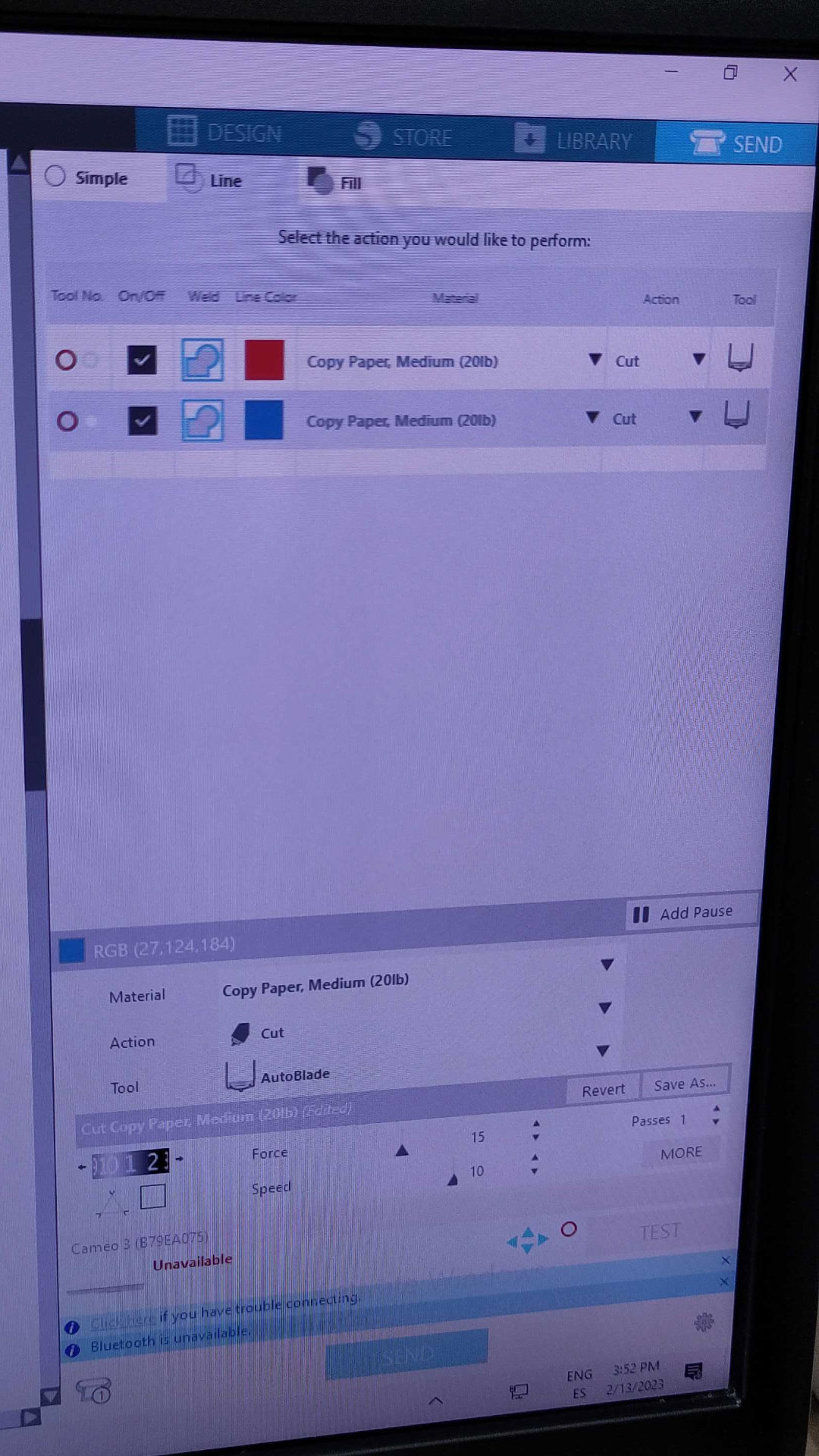
During our group assigment, we found the kerf and laser cut different materials ( acrylic, cardboad and wood) all the documentation is in here I designed in rhino using the thickness of the acrylic 3m, start adding 0.5 mm to each side from 3 to check which was the perfect kerf of the material. (Kerf refers to the width of material that is removed by a cutting process)

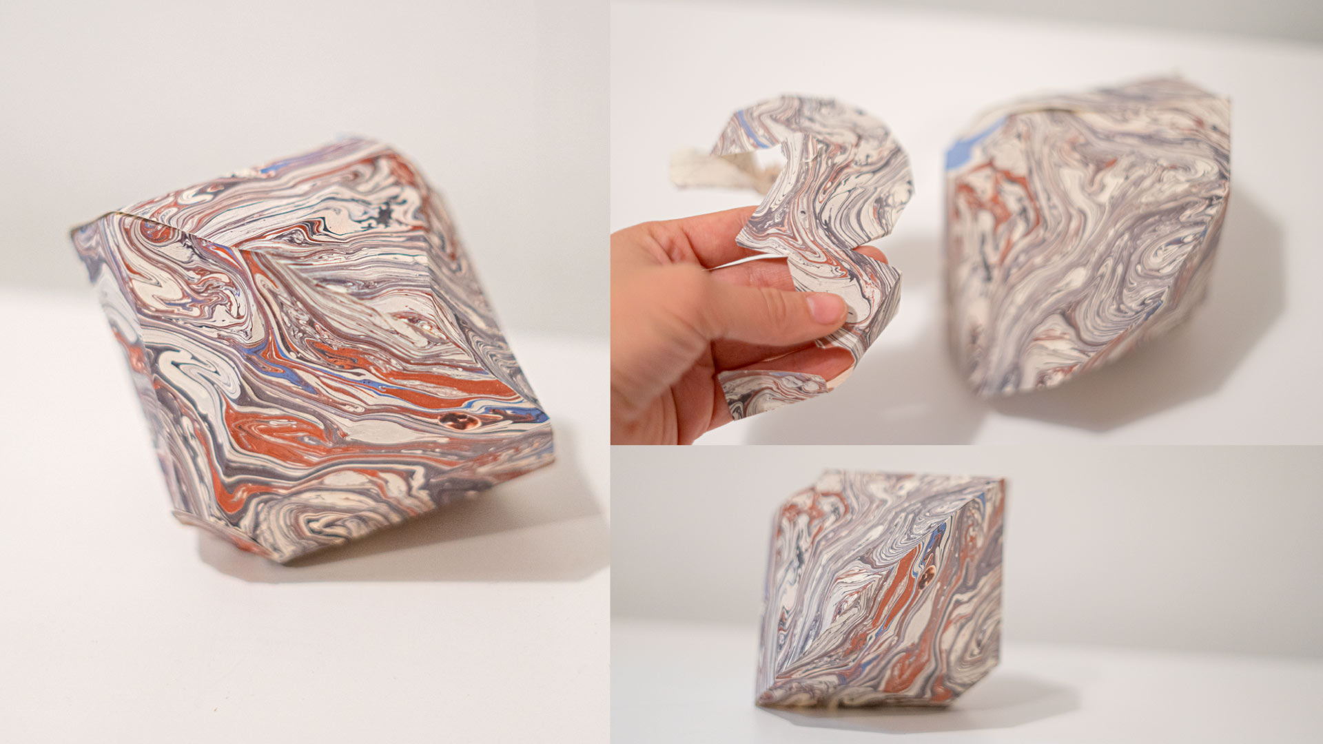
I started on rhino with grasshopper, following this tutorial in order to create a parametric press kit. At the moment, my knowledge on grasshopper is 0, so understanding the basic concepts was a process.

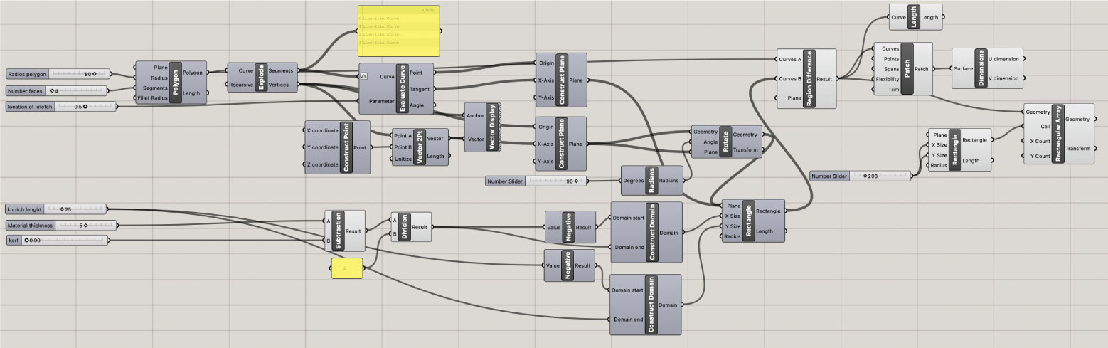
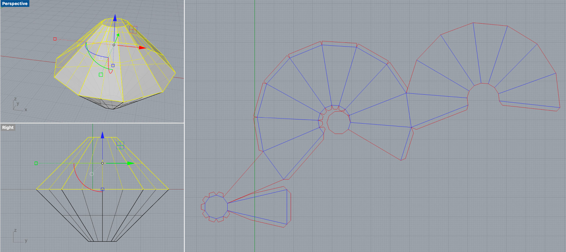
01. Creates vertices on a polygon:
-Start creating a polygon on which define the Radius and the number of segments. Then explode it into curves and analyse the line because we want to create a point in between it.
-Evaluation component: Check the properties of one point in the line. The line of the curve has a parameter, it means in which position we want to evaluate the curve through the line. This is define by the length.

02. Find midpoints:
Reparametrized: This means 0 will be initial length while 1 means maximum length. So in order to use it, right click over curve (in the evaluate curve block) and then scroll until the icon of a curve down.

03. Create a rectangle in order to subtract from:
It needed to add a domain to being able to align to the middle of the midpoint that we found in the step before. When connecting it to the curve block, point to plane, we can see that the orientation of the rectangles are not align to the center. So we need to create a construct plane block to be perpendicular to the vector.
-Command click to disconnect and go back to the origine to take the link off. Then, its created a second rectangles on the vertices of the polygon, this was made by, connecting the rectangle block to construct plane first and then a rotate block ( needed to change from degrees to radiant and apply 90 degrees.

04. To subtract the original form or create a surface
We need to turn off all of the blocks for now and add a Region difference. Here will appear the final outline.

05. Instead of having just half of material thickness, in order to make it parametric it has to be:
Material thickness subtract the kerf (from both sides) divided by /2. Edu recommend having.a multiplication of the kerf by 2 just in case of the material . 
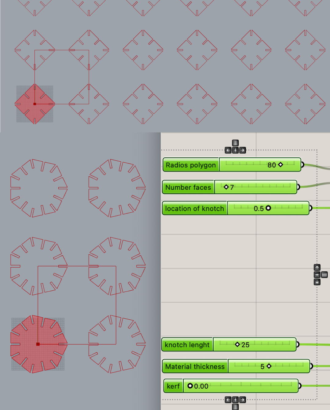
After, organice everything of important matter at the left of the board:

  • - Radius poligon
  • - Location notch
  • - Number of faces
  • - Material Thickness
  • - Kerf
  • - Notch length


  • NOTE!! Always connect the shapes created in rhino with grasshopper, at the beggining on the block curve, right click until you see Internalise data. So the geometry on rhino is link to the grasshopper.

    So, after following the tutorial and having the important sliders to change the parameters, I choose to cut two different number of polygons, one with 4 faces and another one with 7. In addition I added a piece with a shape of an L, in order to connect them without seeing them. Finally, the file was ready, uploaded to the cloud and exported as rhino5 to print.

    Ones I was ready to cut The parameters that I used for cardboard 3mm, first really important to choose the material on the software of the TROTEC Speedy 400, always start with a test of a small circle ( in my case it was only cut, but always try hatch, raster and cut):

  • Power:60% and 80%
  • Speed:100%
  • Frequency:1000Hz


  • 02Stepts to use the lasercut


    Tutorial Trotec Speedy 400

    This week I started creating an 2D image on illustrator, A glass bell composed by six simple shapes and two a bit more organic. I divided each one on a layer, and once I had a sketch of the design, exported as a dxf file in order to model it on rhino.


    01 Load Material Once everything is measure, the air extractor and the machine on, we load the material as flat as possible, better in a concave way to tape in the corners.

    02 Setting focus Hang the focal lense and tap the button until it fells.

    03 Test Before start always test the material first by drawing a simple shape like square or circle and trying engrave-raster. (command hatch for making solid raster, for example in letters)

    04 Print setup First writing in rhino command print and then editing the properties. Size of the machine, minimize the job size, selecting the material and finally pressing the Job Control button.

    05 Job Control Editing the set up, in set move the design to the corner, instead of cutting in the middle of the material. Hide the lines that we are not going to raster fist, and then.

    06 Set up Each material will have a specific power, speed and frequency (H2)this ones are written in the material board at the lab to follow the instructions.

    07 Cut! First check the icon of an usb and connect, so the machine and the computer are connected. Then send to print!


    Vynil cutter

    For this one, I was more interested in cutting paper and creating an origami figure, kind of a paper lanter. Starting on rhino with a pyramid truncated of ten sides. Then duplicated and making boolean union for them to be as one polygon.
    After that, using the unroll surface, the shape was now as a 2D drawing, the only thing missing was creating some extra folds on the material for glueing the pieces. (PentaƱas)
    The last part, was dividing the shape into the outer line that is going to be cutted and the inner lines that are just an engraved in order to fold the pieces.

    The parameters that I used for the paper and the ones I recommended in case that the paper is around 100gr are:

  • Blade: 3
  • Speed: 10
  • Force: 15
  • Passes: 1


  • Silhouette Cameo - Vinyl Cutter

  • Loading the material
    Insert the vynil from the front of the machine, aligning the material to the blue arrows on the side. Then press the button load.
  • Adjust the blade
    Defining the parameters to cut on the computer, choosing how much we want the blade to cut the material.
  • Silhouette Studio
    Opening the software, adding the material as DFX, first adjusting on Design the files (size, rotation, ungroup). Then choosing the machine that we are using, in the labs case, the Cameo. Media size, changing the measurements.
    Going to the tab on the top-right called Send and here adjust the material, the action (cut)and adjust the parameters. Force-speed.
  • Test
    Press test, and is going to cut a square with a triangle in the middle, taking out the square and see if the triangle is staying. (use this in every layer of the file)
  • Cut
    Load the material again, go back to the software and press send. In case if needs mirror (text or tshirts)or was it is. After the machine cuts the design, be really careful taking out the leafover of the material with some tweezers.


    FILES


  • Vynil files

  • Laser cut files


    • Things to learn

      In this case, I made another test on laser-cutting acrylic to understand the difference between cutting, raster and engraving in our machine.

    • 01 First the machine is going to engrave, (in the material description at the lab is what is called raster)
    • 02 In case of having a raster, choose speed 80 or 90, even if it says 100, so the vibration of the machine doesn't disconnect itself.
    • 03 What says engraved in our material description, needs to be written as cut on the job-controller
    • 04 If there are inside cuts to be made, needs to be in a different layer than the outline or final cut of material.

    next project

    Embedded Programming