Inputs are hardware devices that allow to upload data or commands into a computer. In Arduino programming, digitalRead() is a function that is used to read the digital state (HIGH or LOW) of a specific input pin.
The function takes the pin number to read the digital state from. The pin number can be specified using either the physical pin number on the Arduino board (e.g. 2, 3, 4, etc.) or the Arduino pin name (e.g. A0, D7, etc.).
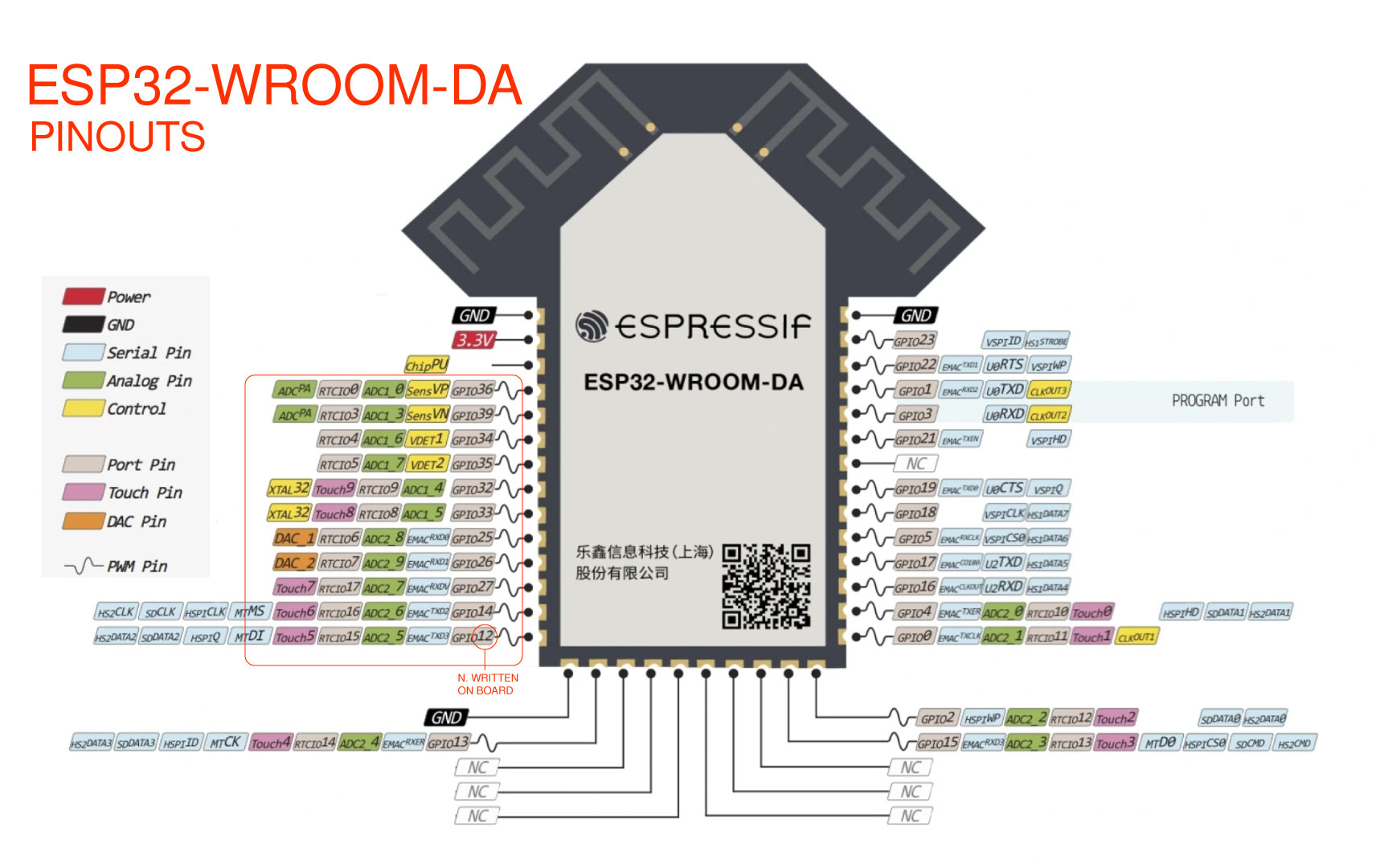
Here was the first thing I had to do some research on, because we use the ESP32 instead of Arduino, there is no Analogue (A#) or digital (D#) written on our barduino, so downloading the sheet, was useful to understand when to use the pinouts, due to, most of the exercise online in youtube and instructables that was my resource for examples.
Week 11
Input Devices
This week we learn about input devices, used to send data or information to a computer or other electronic device.
- Week 21th - to 2th of april
- Keywords electromagnetism, mosfet, steppers, piezoelectric, diodes.
- Software Arduino
- Group assigment
- Here
Group assigment
For this week group assigment we need to probe an input device analog and digital signals and document it on01Inputs
The second big step of this week was understanding in the practice the difference between "analogRead()" and "digitalRead()", both functions in Arduino are used to read input data from pins, but they are used for different types of signals.
The analogRead() function is used to read the analog voltage value on an input pin, which can be a value between 0 and 5 volts. This function is normally used with sensors that output an analog voltage, such as temperature sensors, light sensors, or potentiometers. The analog voltage is converted to a digital value between 0 and 1023, which can be read by the Arduino.
The digitalRead() function, on the other hand, is used to read the digital state of an input pin. The digital state can be either high (5 volts) or low (0 volts). This function is commonly used with switches, pushbuttons, or other devices that output a binary digital signal.
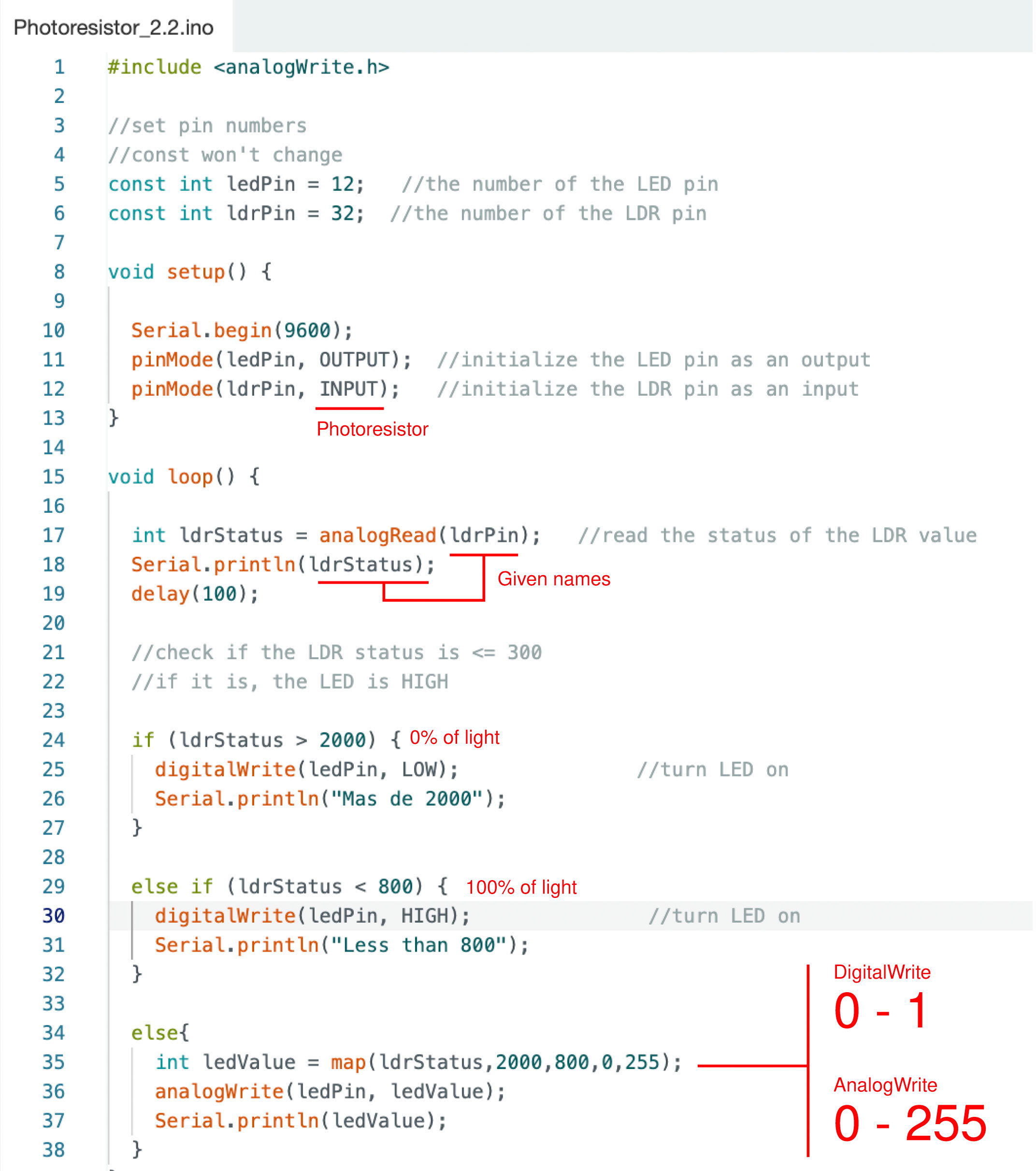
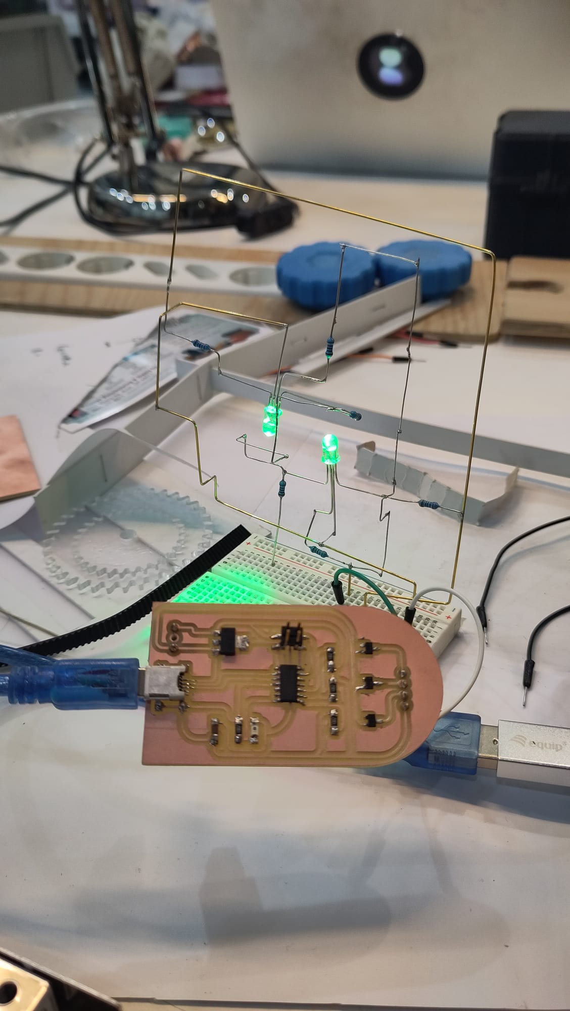
This was useful for the main exercise I worked on this week, I wanted to turn a simple LED on when the light was off. By this, I worked with a photosensor, for the first test, I used digitalread just turning it on and on the light (1-0) so it looked 100% on of 0% off. Instead, by using the analogwrite it was from 0 to 255. In this case, it creates a diffuse effect, and I used the command Map, so thisfunction maps a range of input values to a range of output values. In other words, took the 1-0 and transform it into 2000-800 to 0-255. (2000 was the maximum value sense from the LDR and the 800 was the lowest before turning the led on).
This first test was good as a first approach but it had some problems turning the led completely off. (video on the left)
Then, it was used the command constrain, to do the same but with a better result. Writing the ledValue=constrain(ledvalue,0,255) (video on the right)
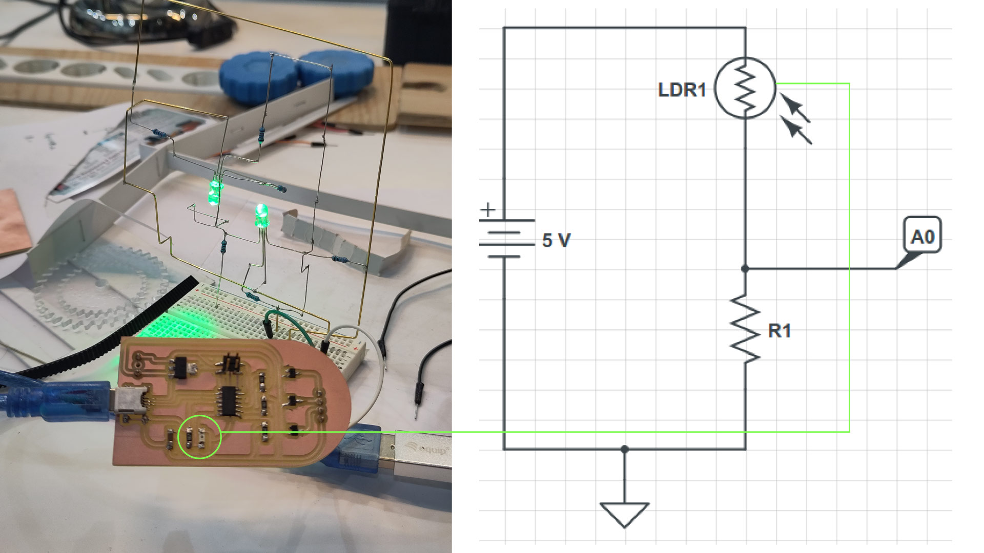
LDR Circuit
I'm going to explain the circuit, for my final project I need to detect changes in the brightness level of the room.For this, I used a light sensor LDR (light-dependent resistor), an electrical resistor, and an LED. In a few words, the idea is that when the light intensity decreases below a certain threshold, the LED activates.
The LDR sensor is a resistive sensor (photoresistor), meaning its electrical resistance varies based on the light it receives. It's an analog sensor, so to read its measurements, when I connected it to an analog input on Barduino. If I covered it with my hand or move the sensor closer to the light, it will see how the measurements change through the serial monitor. The value of the resistor (R1) will determine the sensitivity of the measurements and will also depend on the range of resistances provided by the LDR."
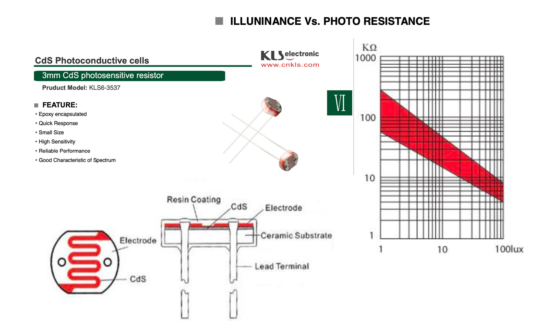
Sensor
This week I'm going to work with the phototransistor that comes in the Electronic fun kit given by the lab in the first week, according to the datasheet its a 3mm CdS photosensitive resistor. Also known as a light-dependent resistor (LDR) or a photocell, is an electronic component that changes its resistance based on the intensity of light falling on it. It is made out of a material(cadmium sulfide) that has photoconductivity,and in my case i'm using this property as light- sensitive circuit, this mean the resistors respond to changes in light intensity. it automaticallychanges the brightness of the led or activates lights when it gets dark.
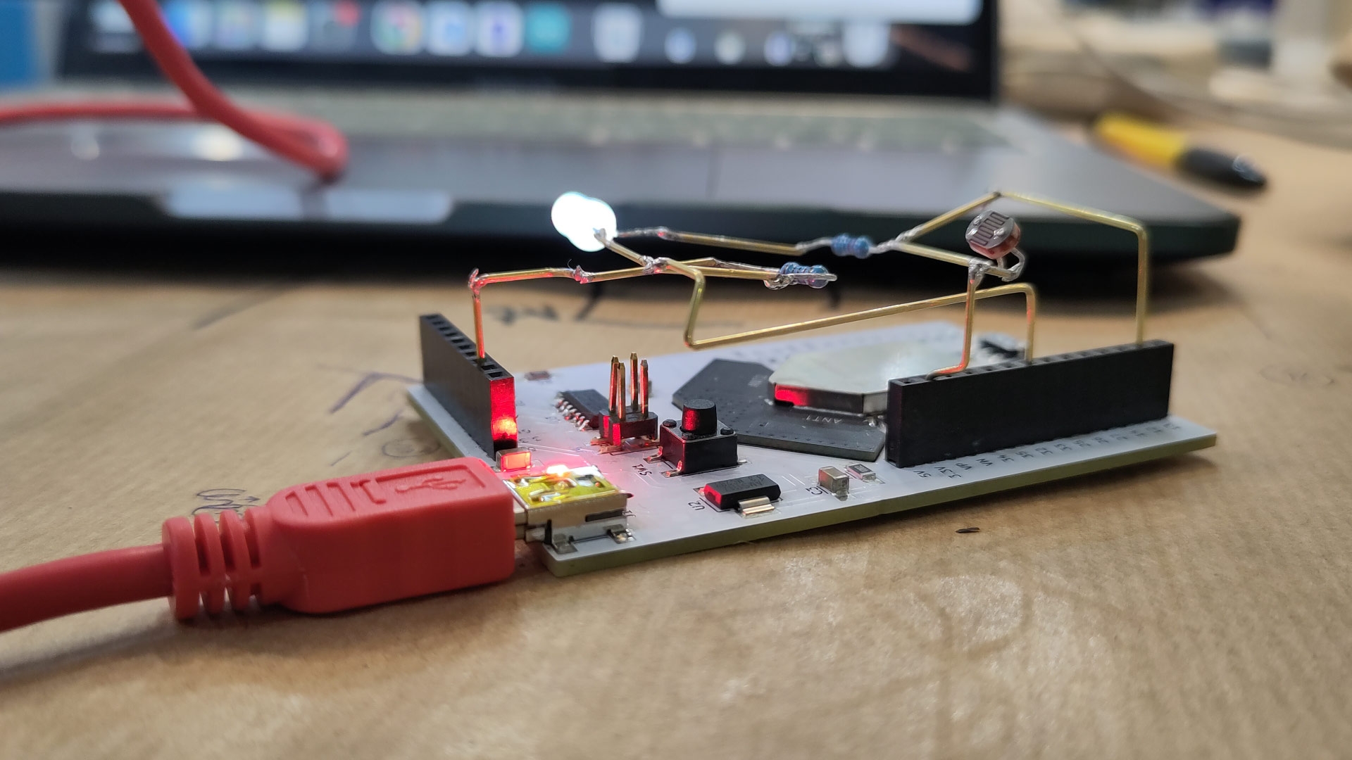
01Test
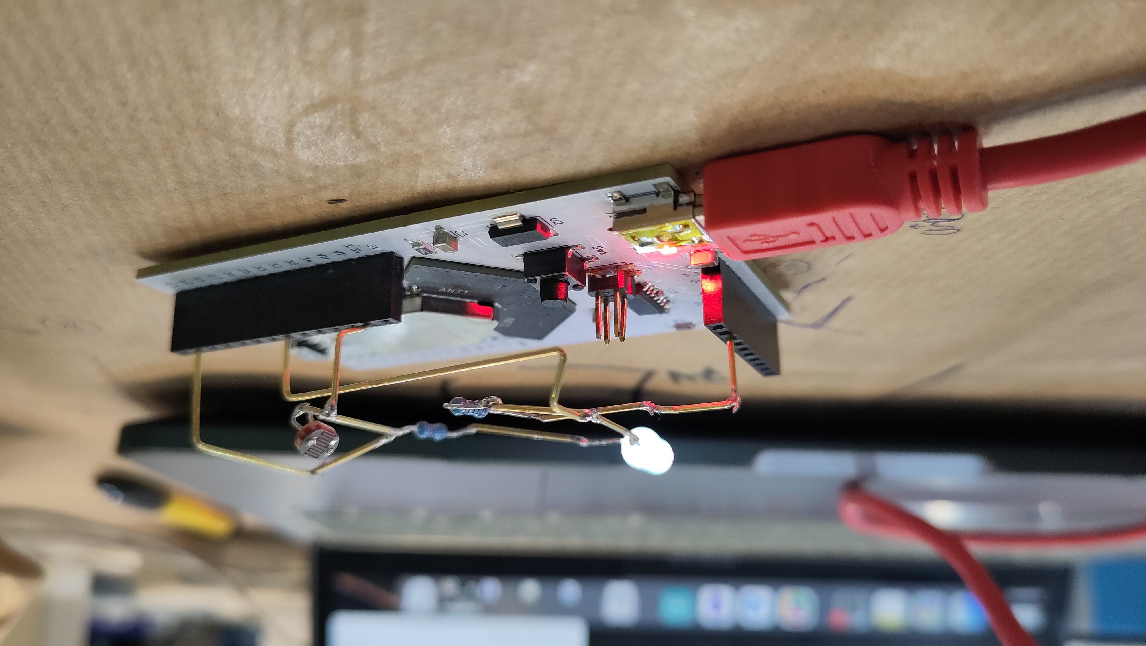
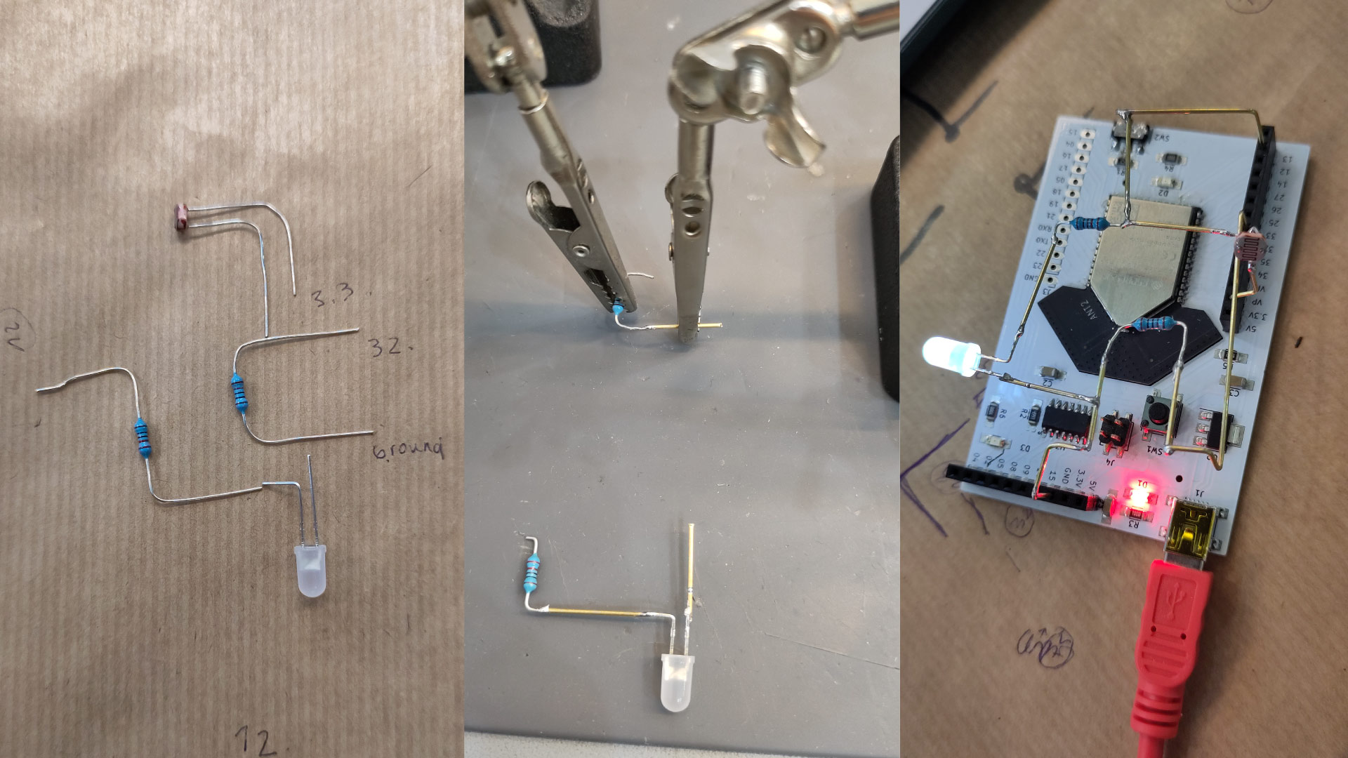
The next step is trying to create the same circuit without a breadboard but still using barduino. So I plan to solder the components together and each one going to each respective pinout. This will be the smallest pretest of my final project. So based on the exercise on turning one led depending on the amount of light in the room I draw in a paper sheet all of the components that I needed to connect with a copper wire, then using the barduino as the based, measure the distances between the components and then using some cocodrile tweezers as hands to have everything ready to solder. It was a fun test that worked at the end with some help from my instructure.
This was the first test for my final project and here are some examples of my board phototransistor reacting to the low light in the enviroment to turn on the leds.
This documentation of the test will be added to the final project page due to is the first experiment.
- 01 ALWAYS check in Arduino that the correct board is connected
- 02 Breadboad serve as test before soldering
- 03 Pin 13 in Barduino is connected to the led on the board to try tests.
- 04 Always switch to the left and press button to read new sketch on Arduino.