12./13. Machine design
Group Work
A detailed documentation of our group assignment work can be found on the shared group assignment webpage.
Machine design week was a horrible kerfuffle for our group. In the beginning of machine design week (or rather: the two weeks including Easter break) I was suffering from a Covid infection which meant 10 days of isolation and no lab access for me. When I was slowly feeling better, my 1- and 3-year ones came down with Covid too - meaning no daycare, but Daddy-daycare only. At the same time, we kind of decided to build a spot welder and started preparations.
System Setup
With me being out of the lab, I started procuring materials from at home - cables, cable terminals, crimping tools, linear actuators and the like.
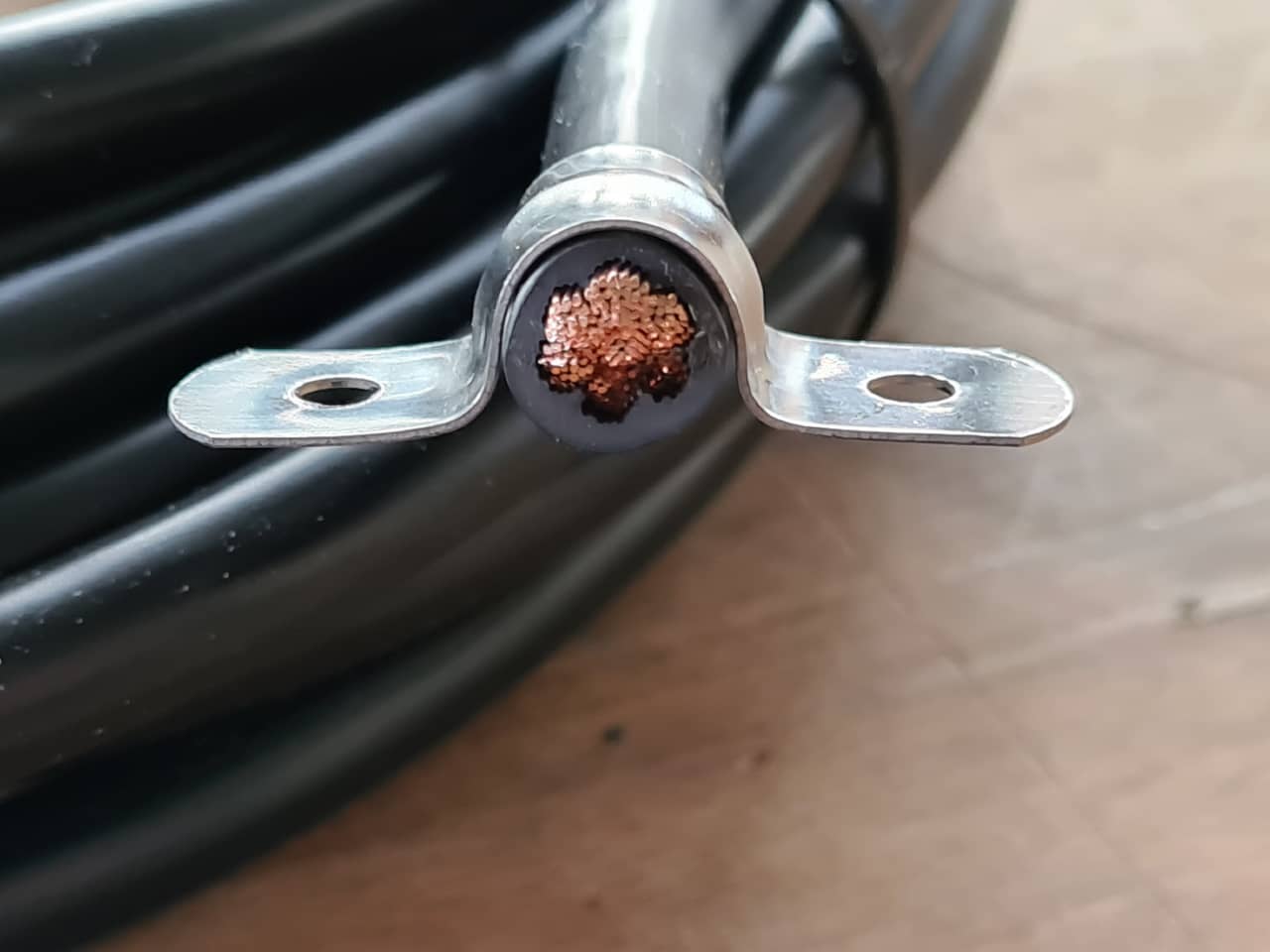
These were the cables (25 mm²) and clamps originally planned for the welder…
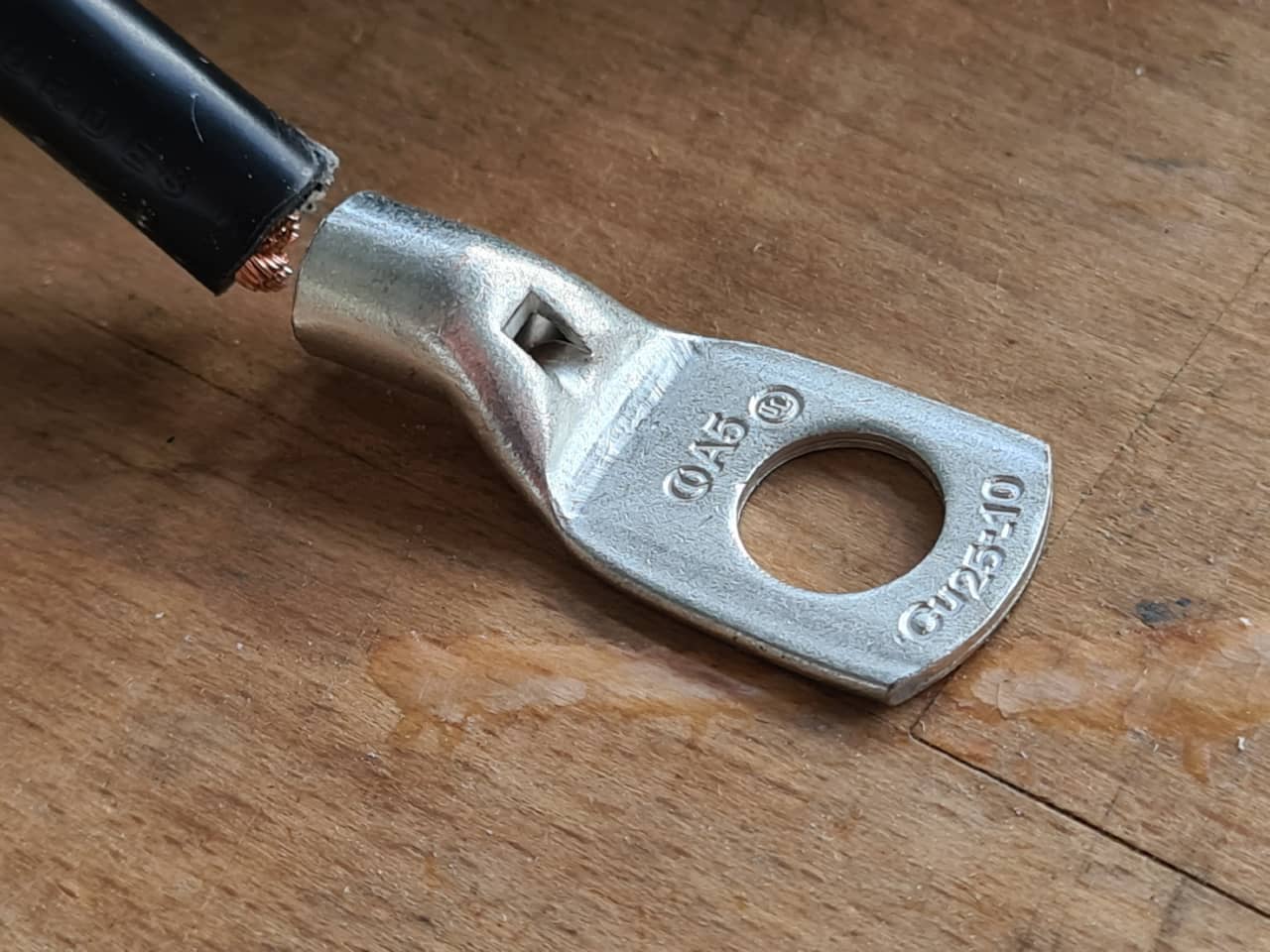
… and the cable would have used these brand cable terminals:
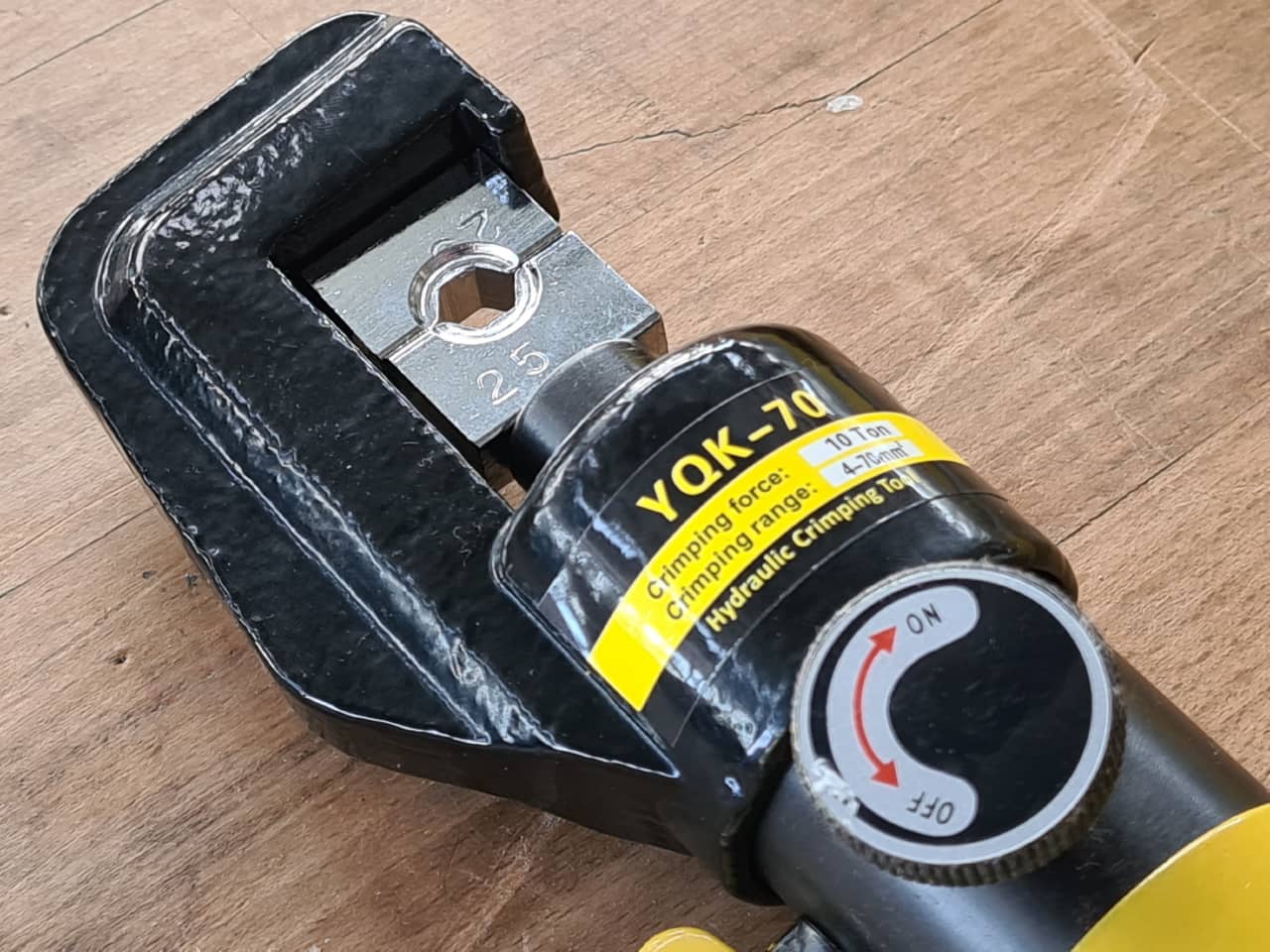
For crimping terminals, there was a hydraulic crimping tool available:
I also started thinking about the programming of the device. In the end, we wanted to have:
- The jaws of the welder should be operable by motor, instead of manual only, to allow holding bigger pieces with both hands and operate the machine by foot pedal.
- The foot pedal was thought to be two-stage: When triggered halfway, the welder would close and then activate current flow using a relay when pressed all the way through. Releasing the foot pedal would stop current flow and open the jaws again.
We decided on following system setup for the welder:
- 12 V Linear actuator to move the jaws
- 5-36 V motor driver to power the linear actuator
- Arduino UNO (running at 5 V) to control everything (also powered from the chosen motor driver, which has a 5 V regulator onboard)
- Micro switch inputs from the foot pedal to control the machine
Linear Actuator Control
I started by testing and programming the motion of the linear actuator using a MotoDriver2 motor driver board, which uses an L298N motor driver IC.
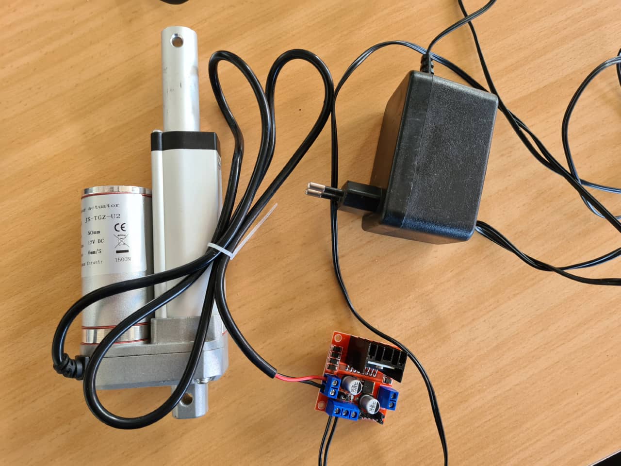
This shows the Linear actuator used, the motor driver board and the 13V power supply:
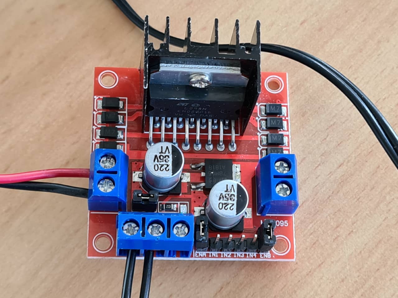
Here we can see the motor driver board. The red and black wires at the left connect to the motor, the bottom two wires are coming from the power supply. No logical connections to the Arduino have been made here, yet:
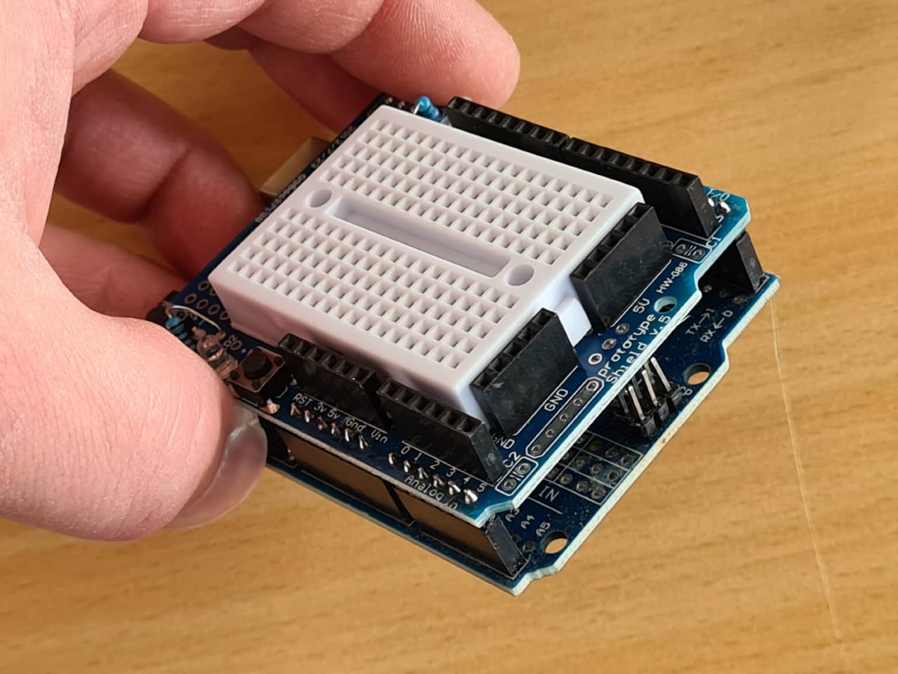
This is the Arduino UNO used for prototyping the setup. We used a prototype shield with a mini bread board on top to quickly make circuit changes on the fly:
The example code from the manufacturers data sheet kind of contradicted other code examples I could find only that used the L298N motor driver IC also used on our motor driver board (I reduced the provided example to one motor only):
//Motor 1
const int motorPin1 = 9;
const int motorPin2 = 8;
int speed = 180;

void setup(){
  //Set pins as outputs
  pinMode(motorPin1, OUTPUT);
  pinMode(motorPin2, OUTPUT);
  //Motor Control in both directions
  analogWrite(motorPin1, speed);
  delay(2000);
  analogWrite(motorPin1, 0);
  delay(200);
  analogWrite(motorPin2, speed);
  delay(2000);
  analogWrite(motorPin2, 0);
}

void loop(){}
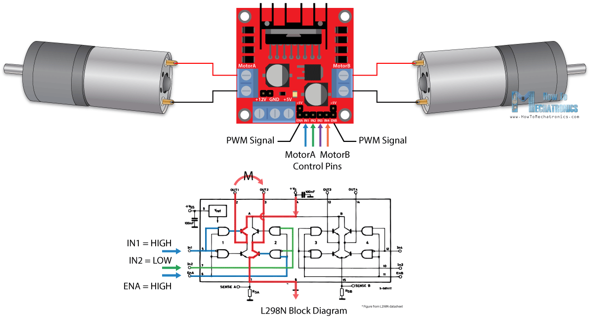
The example above would move the motor, but in the end I went for the more explicit code inspired by this L298N tutorial website, which showed following excellent schematic to illustrate the inner workings of the driver board:
This is the MWE for the motor control using the Arduino:
//Motor 1

const int motorPinEn = 9;
const int motorPin1 = 8;
const int motorPin2 = 7;
int speed = 255;

void setup(){
  //Set pins as outputs
  pinMode(motorPinEn, OUTPUT);
  pinMode(motorPin1, OUTPUT);
  pinMode(motorPin2, OUTPUT);
}

void loop(){
  //Motor Control in both directions
  digitalWrite(motorPin1, HIGH);
  digitalWrite(motorPin2, LOW);
  analogWrite(motorPinEn, speed);
  delay(7000);
  digitalWrite(motorPin1, LOW);
  digitalWrite(motorPin2, LOW);
  delay(200);
  digitalWrite(motorPin1, LOW);
  digitalWrite(motorPin2, HIGH);
  analogWrite(motorPinEn, speed);
  delay(7000);
  digitalWrite(motorPin1, LOW);
  digitalWrite(motorPin2, LOW);
  delay(200);
}
This also used analogWrite (so sending a PWM signal) on the motor driver’s ENABLE pin to control the speed of the motor as intended - the way it was in the official datasheet was a bit more hacky.
In the beginning, the motor didn’t want to move at all, which led me to investigating other L298N code examples in the first place, but then it struck me I had made the simplest mistake - not connecting the Arduino’s and motor driver board’s GND connections. D’uh! Once both GNDs were connected using a jumper, the linear actuator happily extended and retracted.
In the end, I already knew that quite a few more systems would be added to the Arduino later, so I immediately investigated more elegant ways to drive the motor without as many delay() function calls and blocking all the rest of execution. After looking into a number of L298N-centric code libraries, I settled with the L298N_MotorDriver, version 1.0.1 library by author Alex Krieg, which can be found using the Arduino IDE‘s library manager.
The resulting code was a bit cleaner than the code before, even though it still relied on using delay() function calls - yet much shorter ones, not blocking execution as much. I made the motor extend and retract periodically, accelerating and coming to a halt at the turning points. This was fancy enough for now:
#include "L298N_MotorDriver.h"

// Make a motor object
// Arduino Pin 9 ( pin must have PWM capability),
//   is connected to the driver board pin EN (enable)
// Arduino Pin 8, is connected to the driver board pin IN1 (H-bridge path 1)
// Arduino Pin 7, is connected to the driver board pin IN2 (H-bridge path 2)
// Set the pins for one motor which uses this dual driver board.
L298N_MotorDriver motor(9,8,7);

int motorMinSpeed   = 60;
int motorMaxSpeed   = 255;
int motorSpeed = motorMinSpeed;
boolean motorDirection = false;
byte speedInc = 1;
int rampDelay = 20;

// Switches between counting up and down
// to make a ramp up and ramp down for the speed
bool countUp = true;

void setup() {
  motor.setSpeed(motorMinSpeed);      // Sets the speed for the motor. 0 - 255
  motor.setDirection(motorDirection);  // Sets the direction ( depending on the wiring )
  motor.enable();             // Turns the motor on
}

void loop() {
  motor.setSpeed(motorSpeed);  // Sets the new speed
  motor.setDirection(motorDirection);  // Sets the direction ( depending on the wiring )
  delay(rampDelay);              // Wait a bit to make the ramp longer

  if(motorSpeed >= motorMaxSpeed){
      // Changed the rising ramp to a falling ramp
      countUp = false;
  }
  if(motorSpeed <= motorMinSpeed){
      // Changed the falling ramp to a rising ramp
      countUp = true;
    motorDirection = !motorDirection;
  }

  if(countUp){
      motorSpeed = motorSpeed + speedInc;
  }
  else{
      motorSpeed = motorSpeed - speedInc;
  }
}
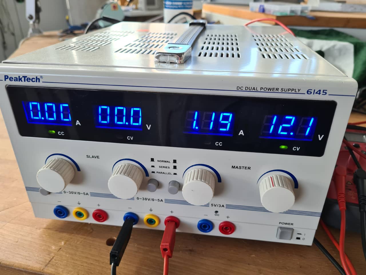
Here is the motor running at 12 V using a bench top power supply to test its extension current:
Huge Changes
Meanwhile (remember: I had been knocked out for a good while of machine design week already, this was around Easter in the final week already), a huge change had been happening to our original design. An individual the university hosting our FabLab raised questions about the electrical, fire and user safety of the homemade device. This raised our awareness about building and using machines like that in an openly accessible space like our FabLab, where there is a lot of general student traffic - and people don’t always stick to the rules of not using machines until initiated…
Long story short: We (painfully) accepted that building a device up to German electrical code to operate in the FabLab was not a thing to be done in the remaining days (and would have involved quite a few external parties, if allowed at all). While a painful lesson, it was also a good lesson. User and fire safety in a space like a FabLab should be paramount and not be taken lightly, just because a YouTube-video showed a similar device working. There’s tons on YouTube videos that show devices I wouldn’t touch with a stick, and while the one we picked as initial inspiration had looked pretty sound, execution in our place would have warranted a whole new level of investigation into the relevant safety aspects. Time to move on.
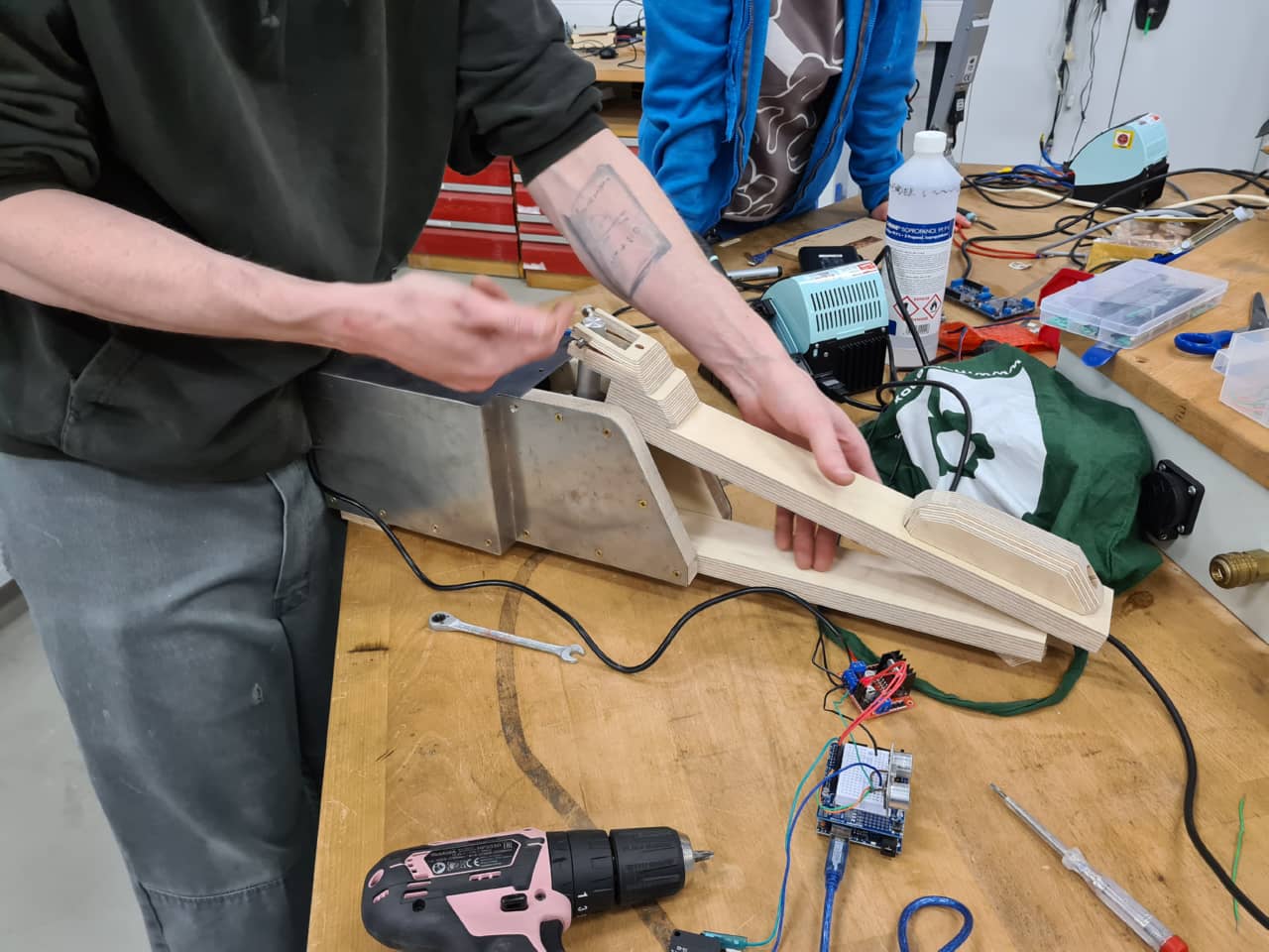
Building on what we had so far
Since starting out with a whole new machine design would not have been possible in the time left, we decided to turn the existing frame and jaw actuation mechanism into a nonsense-machine. The plan was to make a monster/crocodile art piece for kids out of it that could open and close its jaws automatically when someone was standing in front of it or actuating a sensor. Since kids love soap bubbles, it should also spew bubbles while doing so :)
Adding a Sensor - Ultrasonic Range Finder
We wanted to integrate a sensor into the device that would trigger when a user was close enough to the machine or waved her hand in close proximity. At the same time, we wanted to be able to set up the trigger distance in code, since we didn’t know the exact, final layout yet. We decided to go for an ultrasonic range finder, which we have plenty of in the lab. The HC-SR04 we used has a fitting Arduino library that comes with following MWE (change ot fit the pins used on our Arduino):
#include <HCSR04.h>

byte triggerPin = 13;
byte echoPin = 12;

void setup () {
  Serial.begin(9600);
  HCSR04.begin(triggerPin, echoPin);
}

void loop () {
  double* distances = HCSR04.measureDistanceCm();

  Serial.print("1: ");
  Serial.print(distances[0]);
  Serial.println(" cm");

  Serial.println("---");
  delay(250);
}
This code measures the distance from the sensor and returns it via Serial console. If the measured distance is unknown (e.g. when the sensor is too far away from anything to measure) it returns -1.0. The sensor has a measuring range of 2 cm to about 300 cm, so any distance above approximately 3 m will return a -1.0.
Merging Code
The Ultrasonic range finder code was then merged with the motor control code, so that the device would be inactive when no sensor input was seen. Once a certain trigger distance (in our case for testing: 30 cm) on the sensor was hit, the motor would trigger and the device would move its jaws. After one full cycle of the jaws, the device would stop again and wait for input (or continue moving if the sensor was still triggered):
#include "L298N_MotorDriver.h"
#include <HCSR04.h>

// Make a motor object
// Arduino Pin 3 ( pin must have PWM capability),
//   is connected to the driver board pin EN (enable)
// Arduino Pin 2, is connected to the driver board pin IN1 (H-bridge path 1)
// Arduino Pin 4, is connected to the driver board pin IN2 (H-bridge path 2)
// Set the pins for one motor which uses this dual driver board.
L298N_MotorDriver motor(9,8,7);

int motorMinSpeed = 60;
int motorMaxSpeed = 255;
int motorSpeed = motorMinSpeed;
boolean motorDirection = false;
byte speedInc = 1;
int rampDelay = 20;

// Switches between counting up and down
// to make a ramp up and ramp down for the speed
bool countUp = true;
byte reversals = 0; //count number of reversals of direction

byte triggerPin = 13;
byte echoPin = 12;
double* distances;
double triggerDistance = 30.00;

boolean motorMoving = false;

boolean debugMotor = false;
boolean debugSonar = false;

void setup() {
  Serial.begin(9600);
  HCSR04.begin(triggerPin, echoPin);
  Serial.print("Resetting motor...");
  motor.setSpeed(255);      // Sets the speed for the motor. 0 - 255
  motor.setDirection(!motorDirection);  // Sets the direction ( depending on the wiring )
  motor.enable(); //revert motor to original position
  delay(9000);
  Serial.println("done!");
  motor.disable();             // Turns the motor off
}

void loop() {
  if(debugMotor){
    Serial.print("Motor is moving = ");
    Serial.print(motorMoving);
    Serial.print(" (speed: ");
    Serial.print(motorSpeed);
    Serial.print(", reversals: ");
    Serial.print(reversals);
    Serial.println(")");
  }
  if(motorMoving == false){
    distances = HCSR04.measureDistanceCm();
    if(debugSonar){
      Serial.print("1: ");
      Serial.print(distances[0]);
      Serial.println(" cm");

      Serial.println("---");
    }
    if(!(distances[0] < 0.00) && (distances[0] < triggerDistance)){
      motorMoving = true;
      motor.enable();             // Turns the motor on
    }
    delay(250);
  }

  if(motorMoving == true){
    motor.setSpeed(motorSpeed);  // Sets the new speed
    motor.setDirection(motorDirection);  // Sets the direction ( depending on the wiring )
    delay(rampDelay);              // Wait a bit to make the ramp longer

    if(motorSpeed > motorMaxSpeed)
    {
        // Changed the rising ramp to a falling ramp
        countUp = false;
    }
    if(motorSpeed < motorMinSpeed)
    {
        // Changed the falling ramp to a rising ramp
        countUp = true;
     reversals++;
     motorDirection = !motorDirection;
      if(reversals > 1)
      {
        reversals = 0;
        motorMoving = false;
        motorSpeed = motorMinSpeed;
        motor.disable();
      }
    }

    if(countUp)
    {
      motorSpeed = motorSpeed + speedInc;
    }
    else
    {
      motorSpeed = motorSpeed - speedInc;
    }
  }
}
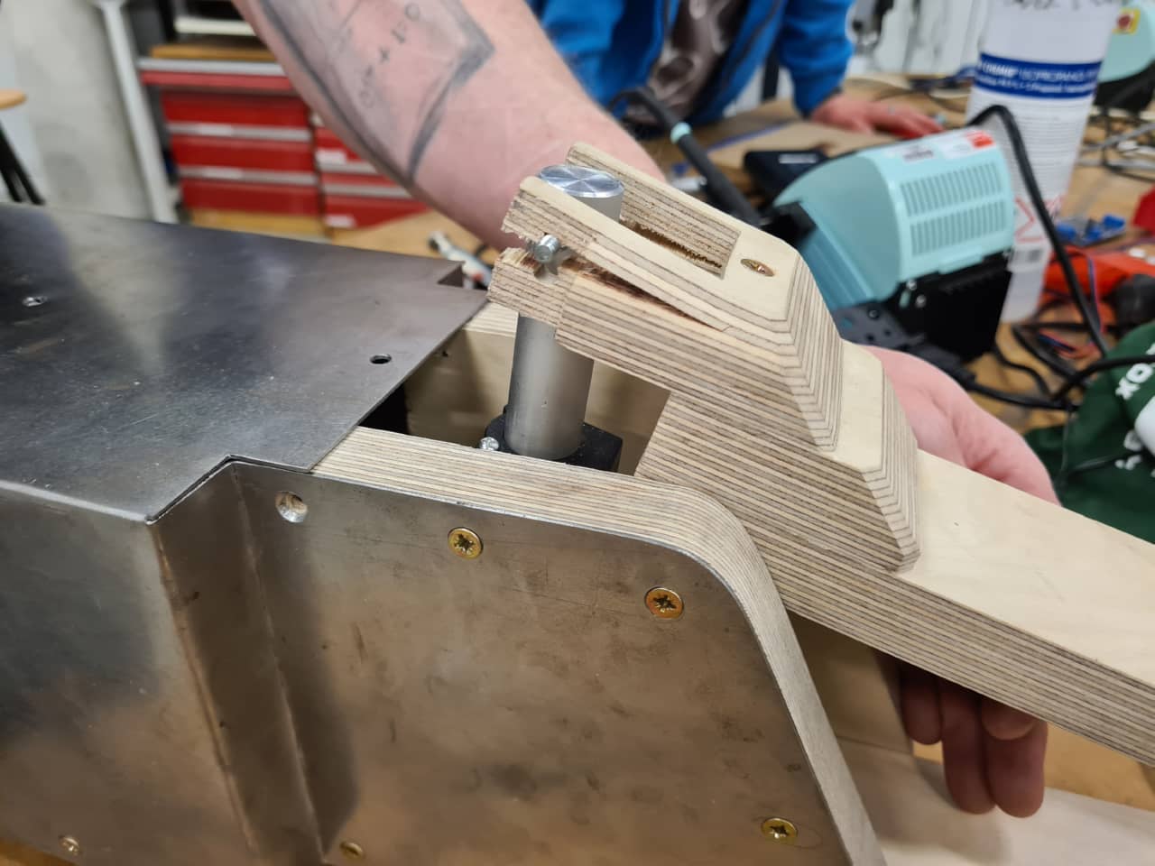
In the setup() function of the Arduino, I also added a timed, 9 second stroke of the motor to fully retrieve it. The motor does have end switches at both ends of the stroke, but no other kind of feedback, so to always start the device in a known configuration, it retrieves the piston until it hits the limit switch whenever powered up. THis was necessary, as in the whole communications kerfuffle over Covid isolation and Easter, we had received a wrong linear actuator, which externally looked the same as the one we intended to buy originally, but had a larger housing and larger dimensions overall. Thus, when the mechanism was built - and even after Aaron made modifications to the jaw to set the hinge pin for the piston higher - the piston was not safe to fully extend or it would risk breaking the jaw. The fixed starting position helped making it move safely. I also tuned the stroke length of the piston such as not extending all the way to the other limit switch of the piston, but so that it stopped and reverted motion in between the end points.
Adding a limit switch
There was one painful moment where the actuator actually extended too far, closing the jaws completely and breaking the hinge drilled into the multiplex - pushing a maximum of 1500 N, the motor did not seem to have any problem doing so… So in the end, we decided to also include a limit switch to allow us to quickly cancel the stroke (while testing) and to set a safe, physical limit when on the machine.
This is the device after a mishap with the mismatched actuator. The jaws closed too much, forcing the hinge and breaking it (this was fixed later by Aaron):
Close-up of the broken hinge:
The piston would simply retract to a safe starting position (such as when powered up) when hitting the limit switch. Adding the limit switch led to following code:
#include "L298N_MotorDriver.h"
#include <HCSR04.h>

// Make a motor object
// Arduino Pin 3 ( pin must have PWM capability),
//   is connected to the driver board pin EN (enable)
// Arduino Pin 2, is connected to the driver board pin IN1 (H-bridge path 1)
// Arduino Pin 4, is connected to the driver board pin IN2 (H-bridge path 2)
// Set the pins for one motor which uses this dual driver board.
L298N_MotorDriver motor(9,8,7);

int motorMinSpeed = 60;
int motorMaxSpeed = 255;
int motorSpeed = motorMinSpeed;
boolean motorDirection = false;
byte speedInc = 1;
int rampDelay = 20;

// Switches between counting up and down
// to make a ramp up and ramp down for the speed
bool countUp = true;
byte reversals = 0; //count number of reversals of direction

byte triggerPin = 13;
byte echoPin = 12;
double* distances;
double triggerDistance = 30.00;

boolean motorMoving = false;

byte limitSwitchPin = 3;

boolean debugMotor = false;
boolean debugSonar = true;

void setup() {
  pinMode(limitSwitchPin, INPUT_PULLUP);
  Serial.begin(9600);
  HCSR04.begin(triggerPin, echoPin);
  Serial.print("Resetting motor...");
  motor.setSpeed(255);      // Sets the speed for the motor. 0 - 255
  motor.setDirection(!motorDirection);  // Sets the direction ( depending on the wiring )
  motor.enable(); //revert motor to original position
  delay(9000);
  Serial.println("done!");
  motor.disable();             // Turns the motor off
}

void loop() {
  if(debugMotor){
    Serial.print("Motor is moving = ");
    Serial.print(motorMoving);
    Serial.print(" (speed: ");
    Serial.print(motorSpeed);
    Serial.print(", reversals: ");
    Serial.print(reversals);
    Serial.println(")");
  }
  if(motorMoving == false){
    distances = HCSR04.measureDistanceCm();
    if(debugSonar){
      Serial.print("1: ");
      Serial.print(distances[0]);
      Serial.println(" cm");

      Serial.println("---");
    }
    if(!(distances[0] < 0.00) && (distances[0] < triggerDistance)){
      motorMoving = true;
      motor.enable();             // Turns the motor on
    }
    delay(250);
  }

  if(motorMoving == true){
    motor.setSpeed(motorSpeed);  // Sets the new speed
    motor.setDirection(motorDirection);  // Sets the direction ( depending on the wiring )
    delay(rampDelay);              // Wait a bit to make the ramp longer

    if(motorSpeed > motorMaxSpeed)
    {
        // Changed the rising ramp to a falling ramp
        countUp = false;
    }
    if(motorSpeed < motorMinSpeed)
    {
        // Changed the falling ramp to a rising ramp
        countUp = true;
     reversals++;
     motorDirection = !motorDirection;
      if(reversals > 1)
      {
        reversals = 0;
        motorMoving = false;
        motorSpeed = motorMinSpeed;
        motor.disable();
      }
    }
    if(digitalRead(limitSwitchPin) == LOW)
    {
      motor.disable();
      reversals = 0;
      motorMoving = false;
      motorSpeed = motorMinSpeed;
      motor.setDirection(motorDirection);
    }

    if(countUp)
    {
      motorSpeed = motorSpeed + speedInc;
    }
    else
    {
      motorSpeed = motorSpeed - speedInc;
    }
  }
}
This used a micro switch connected to a pin using the ATMega’s internal pullup resistor, grounding the pin when it was triggered. When triggered, the same routine as when powering up was executed (retracting the piston fully), then operation would continue by waiting for sensor input.
Adding a Radio
The bubble machine that was originally intended to distract from looking at the welder when active was a totally separate subsystem developed by Leen. Since the bubbles would have been to distract from the Welder, the bubble machine would have had to be placed somewhat away from it. Hence, radio communication using an NRF24 radio should be used to communicate between the bubble machine and the welding machine. More on that can be found in Leen’s documentation. We tried merging the radio function into the main machine’s Arduino code, but using the RF24 library, version 1.4.2 by author TMRh20, we couldn’t get communication working at all, while it did work fine when using another pair of Arduino Nanos for radio communication.
We suspected there might have been some hidden resource conflict between the libraries already used (Range Finder, Motor Driver and Radio libraries), preventing the radio to work from the main Arduino. I’ve had similar things happen using certain tone generation libraries that would then claim certain timers for generating waveforms and blocking said timers from being used by other libraries trying to access. In the end, we decided to keep the existing pair of Arduino Nanos with their attached NRF24 radios and simply trigger the sending Arduino using a pin-to-pin connection on the main machine’s Arduino. Here’s the code with the triggering pin for the bubble machine. Code for the sender and receiver Arduino Nanos can be found in Leen’s documentation:
#include "L298N_MotorDriver.h"
#include <HCSR04.h>

// ARDUINO INTERCOMMUNICATION
int bubblePin = 6;

// MOTOR DRIVER
// Make a motor object
// Arduino Pin 3 ( pin must have PWM capability),
//   is connected to the driver board pin EN (enable)
// Arduino Pin 2, is connected to the driver board pin IN1 (H-bridge path 1)
// Arduino Pin 4, is connected to the driver board pin IN2 (H-bridge path 2)
// Set the pins for one motor which uses this dual driver board.
L298N_MotorDriver motor(9,8,7);

int motorMinSpeed = 60;
int motorMaxSpeed = 255;
int motorSpeed = motorMinSpeed;
boolean motorDirection = true;
byte speedInc = 1;
int rampDelay = 10;
boolean motorMoving = false;

// Switches between counting up and down
// to make a ramp up and ramp down for the speed
bool countUp = true;
byte reversals = 0; //count number of reversals of direction

// SONAR
byte triggerPin = 13;
byte echoPin = 12;
double* distances;
double triggerDistance = 30.00;

byte limitSwitchPin = 3;

boolean debugMotor = false;
boolean debugSonar = true;
boolean debugRadio = true;

void setup() {
  Serial.begin(9600);
  pinMode(bubblePin, OUTPUT);
  pinMode(limitSwitchPin, INPUT_PULLUP);
  HCSR04.begin(triggerPin, echoPin);
  Serial.print("Resetting motor...");
  motor.setSpeed(255);      // Sets the speed for the motor. 0 - 255
  motor.setDirection(!motorDirection);  // Sets the direction ( depending on the wiring )
  motor.enable(); //revert motor to original position
  delay(9000);
  Serial.println("done!");
  motor.disable();             // Turns the motor off
}

void loop() {
  if(debugMotor){
    Serial.print("Motor is moving = ");
    Serial.print(motorMoving);
    Serial.print(" (speed: ");
    Serial.print(motorSpeed);
    Serial.print(", reversals: ");
    Serial.print(reversals);
    Serial.println(")");
  }
  if(motorMoving == false){
    digitalWrite(bubblePin, LOW);
    distances = HCSR04.measureDistanceCm();
    if(debugSonar){
      Serial.print("1: ");
      Serial.print(distances[0]);
      Serial.println(" cm");

      Serial.println("---");
    }
    if(!(distances[0] < 0.00) && (distances[0] < triggerDistance)){
      motorMoving = true;
      motor.enable();             // Turns the motor on
    }
    delay(250);
  }

  if(motorMoving == true){
    digitalWrite(bubblePin, HIGH);
    motor.setSpeed(motorSpeed);  // Sets the new speed
    motor.setDirection(motorDirection);  // Sets the direction ( depending on the wiring )
    delay(rampDelay);              // Wait a bit to make the ramp longer

    if(motorSpeed > motorMaxSpeed)
    {
        // Changed the rising ramp to a falling ramp
        countUp = false;
    }
    if(motorSpeed < motorMinSpeed)
    {
        // Changed the falling ramp to a rising ramp
        countUp = true;
     reversals++;
     motorDirection = !motorDirection;
      if(reversals > 1)
      {
        reversals = 0;
        motorMoving = false;
        motorSpeed = motorMinSpeed;
        motor.disable();
      }
    }
    if(digitalRead(limitSwitchPin) == LOW)
    {
      motor.setSpeed(255);      // Sets the speed for the motor. 0 - 255
      motor.setDirection(false);  // Sets the direction ( depending on the wiring )
      motor.enable(); //revert motor to original position
      delay(9000);
      motor.disable();
      reversals = 0;
      motorMoving = false;
      motorSpeed = motorMinSpeed;
      motor.setDirection(motorDirection);
    }

    if(countUp)
    {
      motorSpeed = motorSpeed + speedInc;
    }
    else
    {
      motorSpeed = motorSpeed - speedInc;
    }
  }
}
This was the final code used for the presentation of the device, with range finder, motor controller, inter-Arduino communication and limit switch integrated.
Lessons Learnt and Future Lookout
We did learn that safety should always be one of the deciding factors in our future designs. Machines in our FabLab are relatively accessible to a certain public, as we have lots of student traffic. We also learnt that we have to communicate tighter as a team, especially when unexpected stumbling blocks (sick team members, sick children, order problems…) are put in our way.
Maybe, in the future, we might find other creative uses for a machine of such frame. Slow-Mo back-patting device? Industrial size tea-steeping machine? Coconut Piercer? We’ll see…