4. Computer Controlled Cutting
This week I worked on different methods of computer-controlled cutting. We used a Silhouette Portrait 2 cutting plotter for CNC cutting with a blade and a Fabulaser Mini CO2 laser.
Background - Computer Controlled Cutting
In our new FabLab (FabLab.blue), I’ve already had the opportunity to work with one of FabAcademy Alumnus Daniele Ingrassia’s prototype laser cutters - the Fabulaser Mini. Besides that, when it comes to cutting, I do have a little bit of experience from using a Silhouette Cameo 4 at home for making some simple heat transfers and stickers for the little ones - I haven’t ever fully explored the machine though.
The Vinyl Cutter - How does it Work?
In most cutting plotters, the cutting head only moves on rails on the x-axis (left-right). Movement in the y-axis (forward-back) happens by feeding the medium to be cut into and out of the machine. To make that possible, the medium to be cut has to be affixed to a cutting mat that feeds into the machine using rollers. Cutting mats are adhesive, so that the whole medium can be tacked down firmly - this also keeps material from moving when the cutting knife is dragged through it to make a cut. Of course, thin paper cuts easier than thick cardboard, so the market offers varying levels of adhesion (usually light-standard-strong) for different media to be cut. Once the medium has been fixed to the cutting mat and fed into the machine, the machine follows the cut paths as designed in vector format while pressing the knife into the material. The knife can usually swivel around the vertical, so the blade can always follow the cut direction, though different tools do exist for different applications, too (rolling knives, heavy duty knives, embossing pins, marker pens…). Some plotters can even actively turn the knife without relying on it being passively rotated, which helps making clean cuts especially in thick materials.
Using the Vinyl Cutter
In our FabLab, we have a Silhouette Portrait 2 vinyl cutter. It possesses an 8 x 12 inch cutting mat, so that’s pretty much the maximum size it can cut. The Portrait 2 cuts many types of vinyl (e.g. stickers, heat transfers), but also paper. We do have an auto blade installed on the machine, so there is no manual cutting depth setup.
Setting up the Machine
First thing first, we set up the machine. The Portrait 2 can be connected via Bluetooth or USB. Since it was sitting right next to me on the table, I connected it to my computer via USB. After also connecting the power brick and turning the machine on, we were nearly ready to go. The one crucial thing that was still missing was the software.
Vinyl Cutter Software
Silhouette Plotters are controlled using the Silhouette Studio software. The free version of the software does have a lot of features, though also lacks basic functionality like SVG file import. In hindsight, I was happy to learn from a fellow, continuing student (thanks, Dan Meyer!) that Silhouette plotters are meanwhile also supported by the Inkscape plugin Inkcut for direct control - this saves the conversions necessary to get a vector file from Inkscape into Silhouette Studio.
Installing the software on Windows is as easy as going to the Silhouette Studio download page, downloading the proper version (32-bit or 64-bit) and running the installer. The main, important areas of the software are the DESIGN and SEND tabs, where designs can be created and then sent to the machine.
The SEND Tab - Cut Parameters & Machine Control
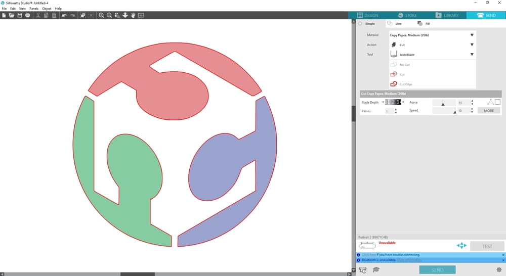
The following screenshot shows the SEND tab in Silhouette studio. Annotations in the screenshot are explained in the text below.
 |
|---|
| The SEND tab in Silhouette Studio. |
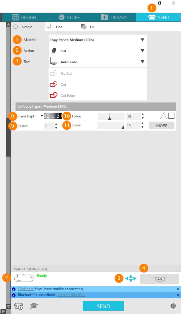
After starting the software and switching on the machine, the connection status can be checked by going into the “SEND” tab (1) at the top right corner of the screen and checking connection status at the bottom of the right sidebar (2). In here, the cutting head can also be manually moved (“jogged”) using the arrow symbols (3). A test pattern can be cut using the chosen cut settings even without a design at all by pressing TEST(4).
Generally speaking, whenever starting out with a new material, proper cutting parameters for said material have to be found. For each combination of material (5), desired action (6) and tool (7), a parameter preset can be created consisting of following parameters:
- Blade Depth (8): The blade can be extended and retracted into the knife toolhead housing to allow cutting materials of varying thickness. I an ideal world, the cutting depth should be exactly equal to the material thickness, so only the material is cut without damaging the cutting mat. In the real world, with all of its fudge factors, cutting depth usually has to be a bit higher than material thickness, so the material is cut all the ways through consistently. Usually, this results in a very light scoring of the cutting mat, leaving visible marks. This is the normal case though and to be expected - the cutting mats will still last for many, many cuts, but they are a consumable item.
- Passes (9): How many passes to take when cutting the material. Some materials can only be cut cleanly doing multiple, shallow passes instead of one very deep cut.
- Speed (10): How fast the machine cuts. General rule of thumb: Faster cutting = less clean cuts and corners.
- Pressure (11): How much pressure is applied downwards when cutting. If too much pressure is applied, the material (e.g. fabrics) could be dragged along with the knife and/or embossed or scratched by the cutting head. With too little pressure, the knife might not make it all the ways through the material and be pushed out of the cut.
The DESIGN Tab - Creating and Manipulating Designs
The following screenshot shows the DESIGN tab in Silhouette studio. Annotations in the screenshot are explained in the text below.
 |
|---|
| The DESIGN tab in Silhouette Studio. |
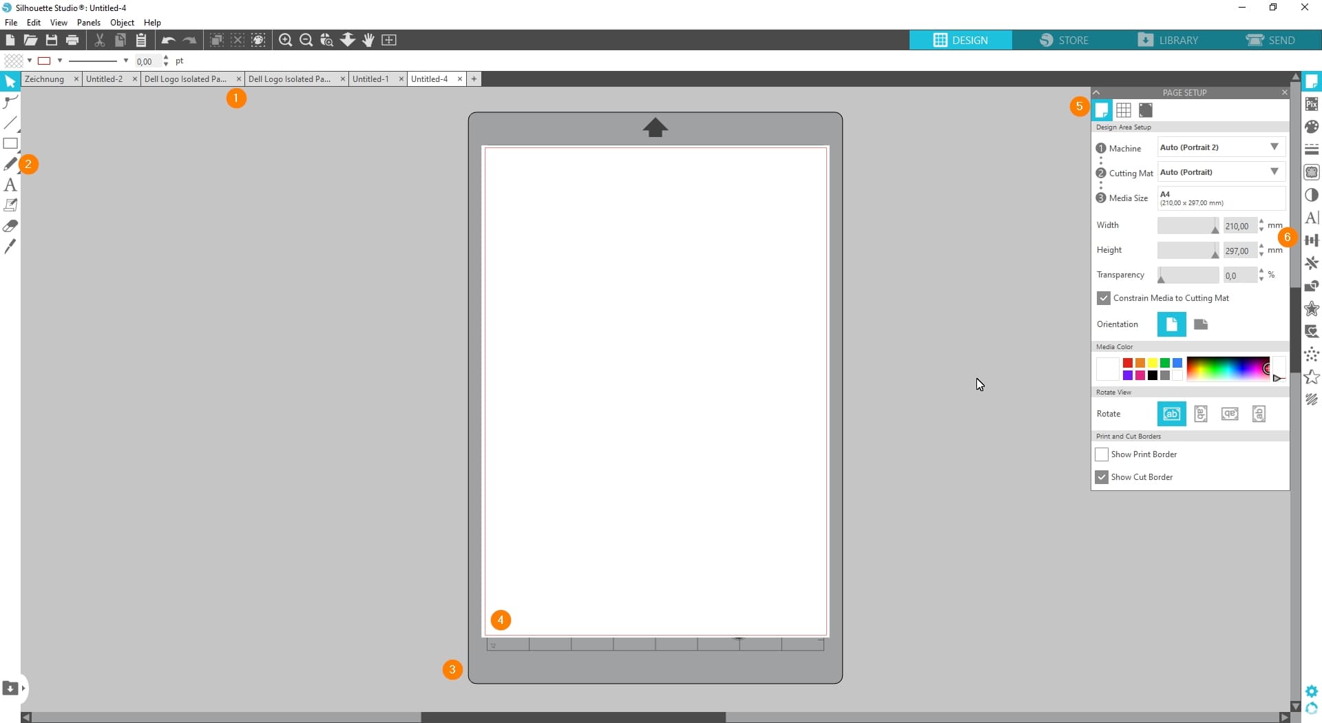
Designs to be cut can be added to the blank page on the DESIGN tab of the software. Open designs can be found under the tabs at the top of the screen (1). Since the blade has to cut along a line, pretty much all designs are, at their core, vector designs. Raster images can be added to Silhouette Studio designs, too, as the software can print raster images and then cut the outline (e.g. for making printed stickers) afterwards. Most tools in the DESIGN tab are tools to manipulate and/or create vector shapes, like lines, squares or circles (2). The center of the window shows a representation of the cutting mat (3) with a medium attached (4). Additionally, on the right hand side, there are a lot of different editing tools to work with too. For example, here the cutting mat and medium can be set up (5). Other tools (6) allow tracing of raster images to vector shapes (which works pretty well and very fast, too), welding, intersection and combination of shapes and so on.
Since my 2D-CAD software of choice is Inkscape, I did not waste too much time actually using Silhouette Studio for anything beyond tracing a raster image and controlling the cutter though - the whole Silhouette ecosystem for my taste is too much of a walled garden, so I’d rather not have my source files in a format only Silhouette Studio can work with in the end. This might be different if one has the Designer edition of the software available, as that one has a lot more options for im- and exporting file formats.
First Cuts
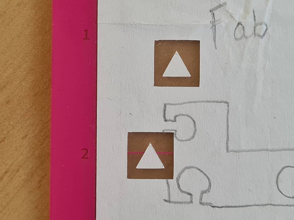
Luckily, Silhouette Studio comes with a plethora of different material presets, which, from my experience, either work right out of the box or are at least a very good starting point to modify settings from. We did our first test cuts using standard copy paper. After applying the copy paper to the cutting mat and feeding it into the machine, in Silhouette Studio we went to the SEND tab and selected the material preset Copy Paper, Medium (20lb). Even without creating a design at all, Silhouette Studio allows for testing the cut using a standardized testing pattern (a little triangle inside a square, ca 1 x 1 cm). To cut the standard test pattern, the cutting head can be moved manually to any place on the paper by using the little arrow buttons in the bottom of the right sidebar. By simply pressing TEST the plotter is instructed to cut the test shape. After cutting, the test shape can be checked for proper material separation by trying to pull off the material inside the square, leaving the triangle behind on the cutting mat if everything is cut properly.
 |
 |
|---|---|
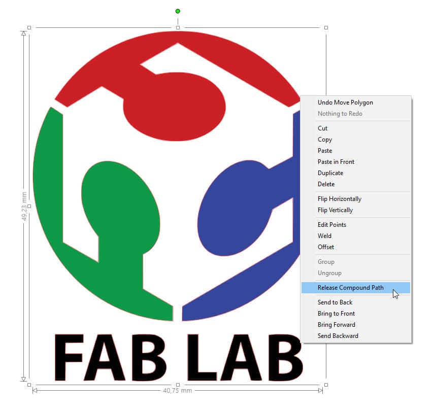
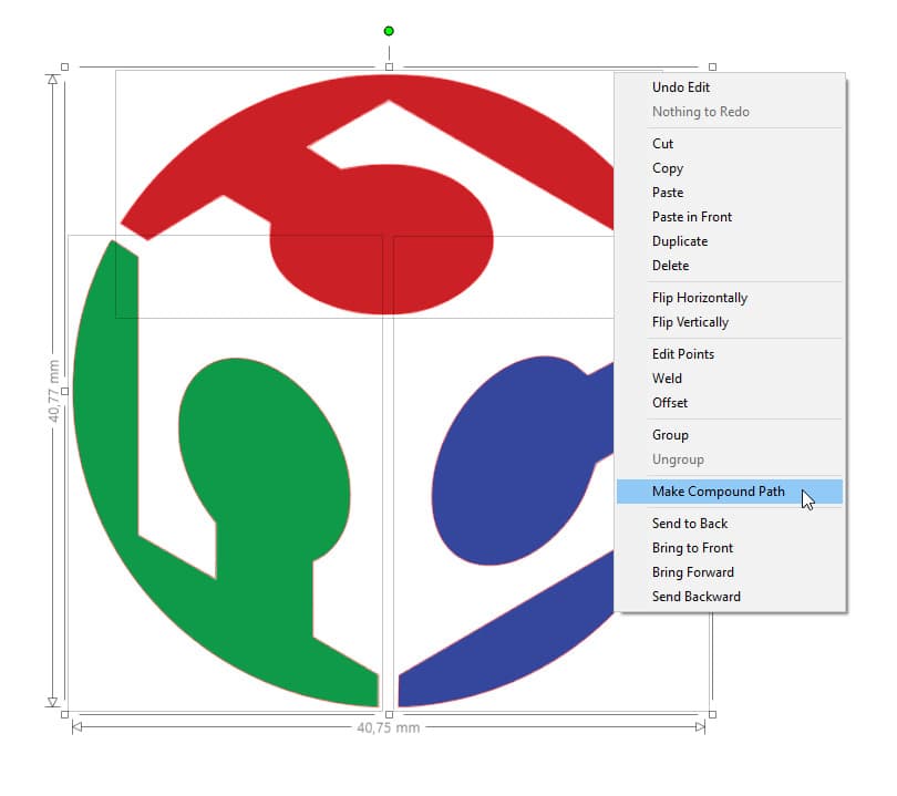
| Silhouette Studio Cut Test Pattern cut from copy paper, weeded. | Fab Lab logo, downloaded from Wikipedia (https://de.wikipedia.org/wiki/Datei:Fab_Lab_logo.svg), opened in Silhouette Studio, split into parts by choosing “Release Compound Path”… |
 |
 |
 |
|---|---|---|
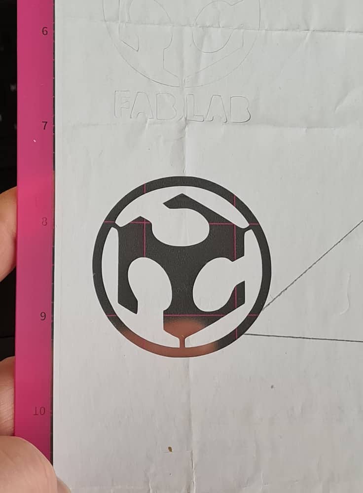
| …then fused back together after removing text by choosing “Make Compound Path”… | …and sent to the vinyl cutter using the SEND tab. | FabLab logo cut in copy paper, unwanted parts of the logo weeded. Above the logo: remains of an earlier attempt to cut the logo that also had the text underneath, not weeded. |
Weeding
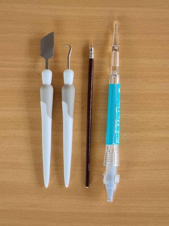
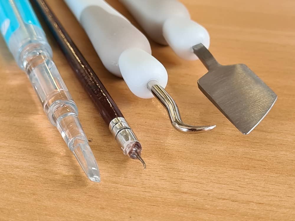
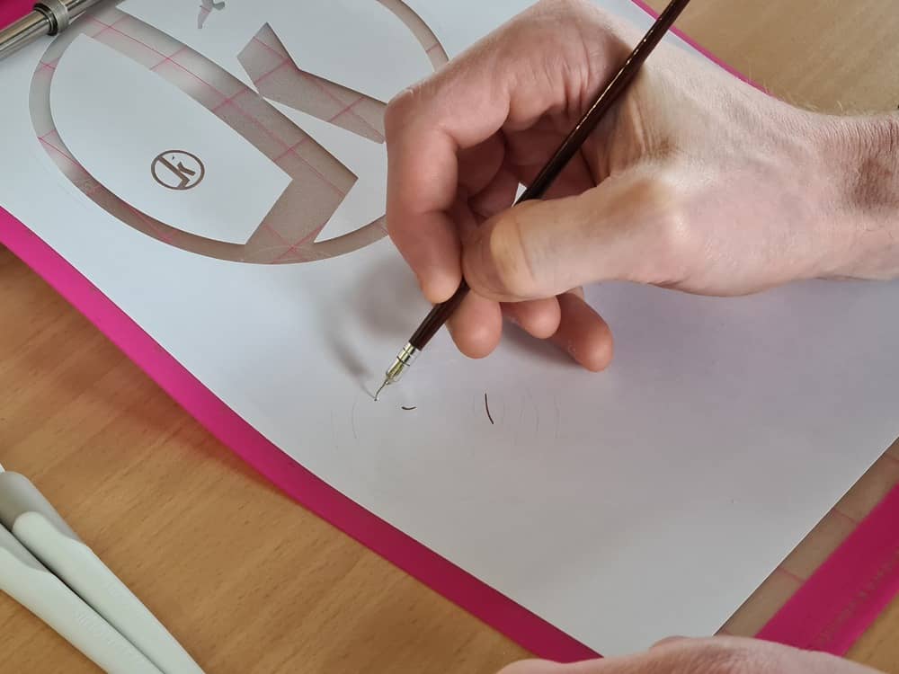
For removing parts of the material that are not part of the design, so called weeding tools can be used. There really is no one weeding tool - weeding tools come in all kinds of shapes and sizes. Some are shaped like a spatula, allowing to slip under the cut edge and lifting the material with the surface of the spatula. Others are shaped like flat bladed screwdrivers. Even others are shaped like little hooks that can pierce the material and lift it up. My favorite weeding tool is one I built myself long ago: A needle with the tip bent over on a hard surface set into the tip of an old paintbrush using hot glue. It is small enough to weed even very fine details and has a very pointy tip that easily grabs onto most materials - whereas some commercial ones are sometimes so blunt they don’t even pierce the material.
 |
 |
 |
|---|---|---|
| Weeding tools (l. to r.): spatula, hook, homemade hook, pick-me-up tool… | …and their weeding tips in detail. | Fellow student Aaron Hinkle weeding a part using the homemade weeding hook. |
Making a Sticker
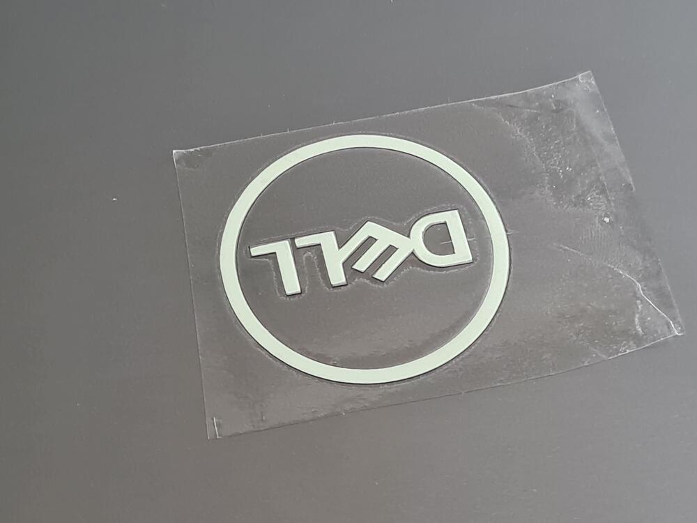
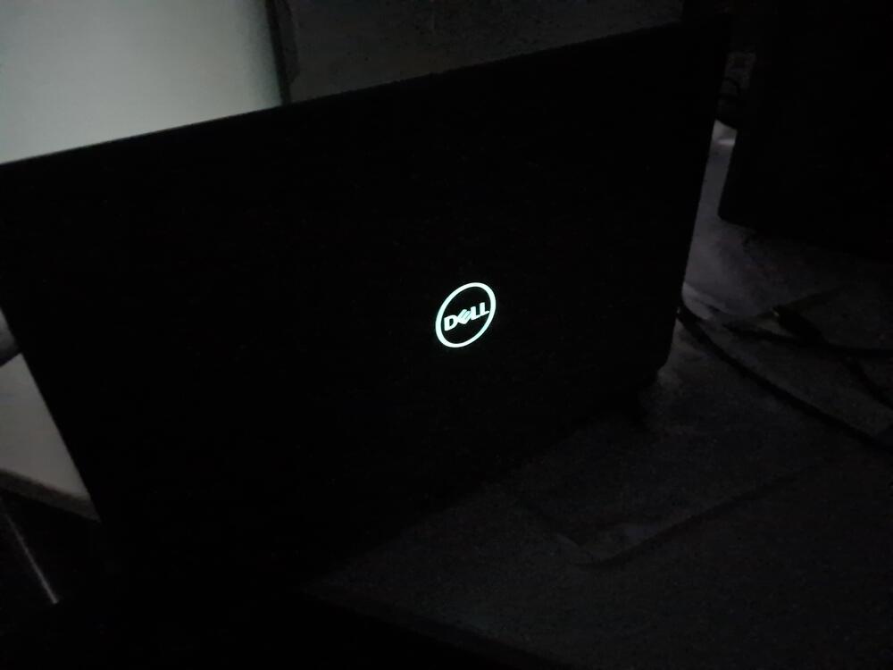
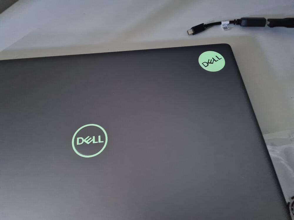
After doing first test cuts with copy paper, I traced the DELL logo on my laptop by scanning it with a ruler on a flatbed scanner, then importing the picture into Inkscape and manually tracing the letters of the logo. I most probably could have gone and downloaded a DELL logo in vector format ant it would have fit, but since there is a small recess in my laptop’s lid (the logo is embossed), I wanted to make sure it fit perfectly. After tracing the logo as a vector format, I used the Silhouette Studio software to cut it from Glow-in-the-dark sticker material. I then weeded the design and used transfer tape to transfer the sticker onto my laptop. Since the negative was usable, too, I also applied the weeded section to the laptop lid.
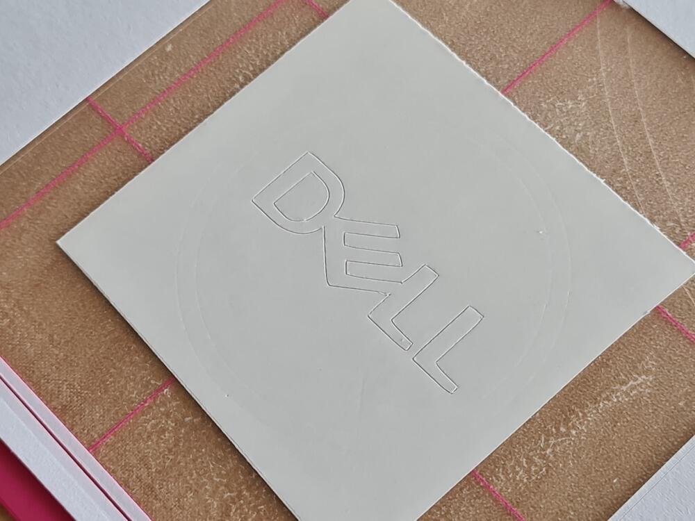
I began by test cutting the sticker on paper…
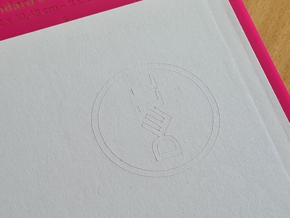
…and then weeded the design for better visual representation.
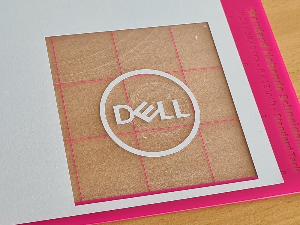
I then committed, cut a piece of sticker vinyl the size needed for my sticker and added it to the same area where the paper sticker was cut before - and cut using the Silhouette preset for Glow-in-the-dark stickers (which, being a Silhouette product, worked very well.):
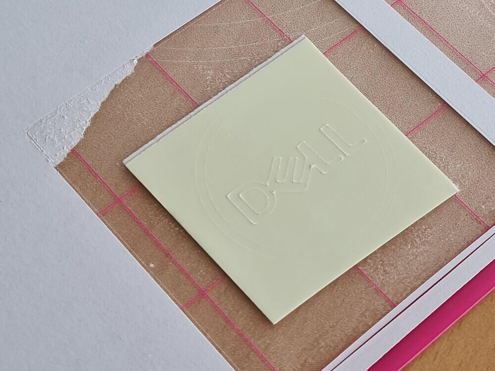
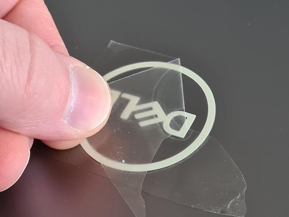
I then weeded the design and transferred the sticker to the laptop using transfer tape, setting it into the recess…
…and peeling off the transfer tape.
Here’s an example of a mishap, where I cut the letters using the correct material preset, but the outline was cut using a different preset not strong enough:
Here’s the sticker applied to the logo, in a dark room, after charging it up with a flashlight:
I then also went ahead and added the weeded negative to the laptop, here in the dark…

…and at ambient light.
Problems encountered
- Sometimes, the grid preview in Silhouette Studio and the grid on the cutting mat were not actually registered well. When adding stock to the (physical) cutting mat and then placing a design on the virtual cutting mat representation where the stock should be, it sometimes really wasn’t.
- When removing paper from a standard-adhesive cutting mat, the paper can sometimes delaminate and leave behind large patches of paper.
- Paper plots cannot really be removed from the cutting mat without destroying them - here, a weakly adhesive mat would be needed. On a standard mat, the paper has to be rolled off the mat to not rip, usually crinkling it to the point where it is unusable.
- Care has to be taken to not cut to deep into the cutting mat. Cutting without or with very thin media, with high cutting force and heigh cutting depth, the plotter can actually cut right through the cutting mat itself.
The Laser Cutter
In many ways, the laser cutter is a different beast than the vinyl cutter: it’s messier, it’s more technically difficult and it poses much more severe health hazards. Any laser cutter uses some or another way of creating a laser beam and then focusing the laser beam onto a wor piece to vaporize, burn or melt it away locally, thus removing the material. By simultaneously doing so and moving the focused laser beam along a predetermined cut pattern, the laser cutter creates continuous cuts, freeing the cut pieces from the bulk material. In this context here, we are only going to talk about the laser in our lab: a Fabulaser Mini. This laser is a CO2 laser with a 40 W tube producing the laser beam. These kinds of tube lasers usually have the tube stationary in the back of the machine (as it’s bulky, fragile and needs water cooling). The laser beam is then sent to the moving cutting head using a system of mirrors and finally focused down onto the workpiece by a lens in the cutting head. Our FabLab’s specific laser cutter was characterized in our group assignment.
Safety concerns
When dealing with a laser cutter, there are several safety concerns:
- The laser has to either be fully enclosed, so no stray beams can escape and cause damage to the operator or bystanders. Safety mechanisms have to be implemented to safely turn the laser off when the enclosure is opened. This is especially important since the wavelength used by a CO2 laser does not trigger the human blink reflex, so the body does not even know what’s happening to it.
- When vaporizing, burning or melting away material, usually hazardous vapors and smokes are produced that should not be inhaled. A laser cutter thus needs a good system of filtering and ventilation (best venting the filtered air outside).
- Since lasers work with heat and often combustible materials, care has to be taken to not start big fires inside the laser cutter. An air assist system blowing compressed air into the cut while cutting can quickly extinguish small flames, so no big fires are started.
- Smoke and vapor can settle on the metal grid usually used for holding the material stock up. When removing cut parts and stock, those remains can be transferred to the skin, causing discoloration and/or penetrating into the skin. Care should be taken to keep the grid clean, wear gloves when needed and wash hands frequently when dealing with the laser cutter.
A Simple, Parametric Design
Supply-side time management showed its ugly teeth this week: I am moving house at the moment1 (even though a move, one might argue not a very smart one…), so little time could be set aside to really tinkering much with the laser. For my press-fit parametric kit I thus decided to go with something easy and not go for the high-hanging fruit. I decided to program a parametric OpenSCAD generator for box inserts, e.g. for partitioning board game boxes and the like. This will be useful for me, as I like boardgames and have plenty of them (many of which could use some organization) and I have two little children that tend to destroy whatever means of organization is already there. I am aware that there are generators for making such box inserts out there - but I couldn’t find any in OpenSCAD that would have the feature set I had in mind. The closest to what I wanted to do probably was this thing by Thingiverse user Factotum that would create a single divider, but only with very crude, simple, square slots. I was envisioning a bit more detail.
Laser Slots
I decided I needed a way to reliably and quickly generate slots of different sizes and geometries. Here’s what I did first:
- Program an OpenSCAD module (
laserSlot.scad) for generating laser slots that- were variable in both width and depth
- had a variable chamfer (in both chamfer length and chamfer angle) for easier assembly
- could also have circular clearance cuts at the base of the slot
- could easily be flipped to generate slots on either side of a board
- outputs 2D shapes that can directly be subtracted from 2D shapes in reusing code or extruded into a body for subtraction
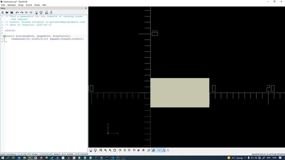
I started out with a very basic, rectangular shape…
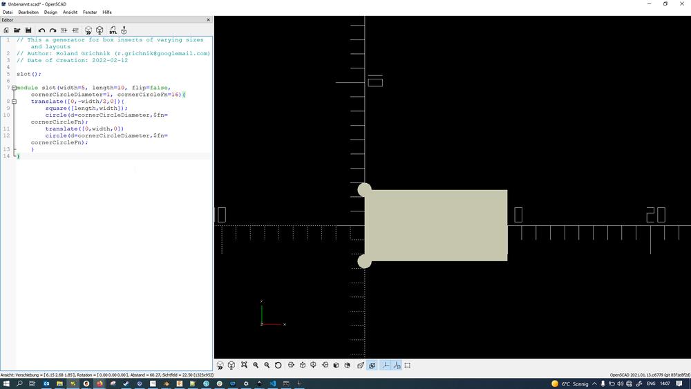
…then added circular clearance cuts/stress easing to the base of the slot shape…
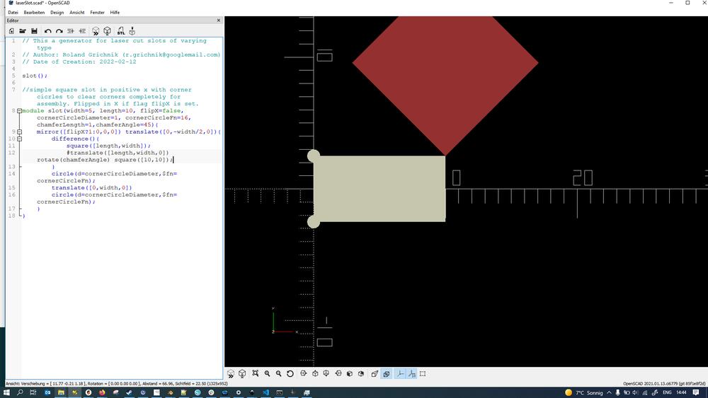
…tried to use a rotated rectangular shape for the chamfer at the top of the cut but quickly found that to be too hacky and…
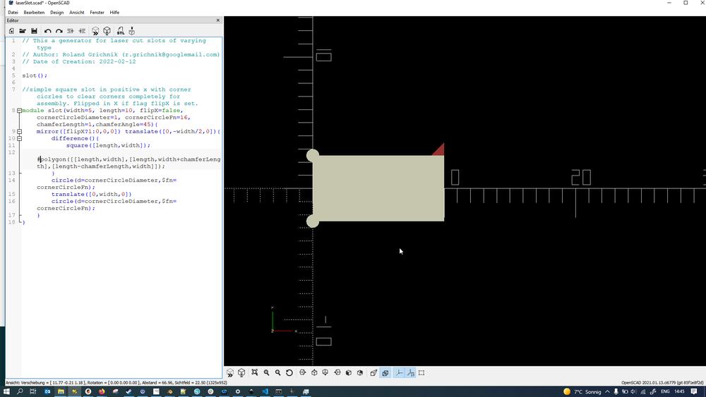
…instead created the chamfer shape using a polygon.
This is what the whole slot shape (as a positive, keep in mind this shape will later be stenciled out of material like when using a cookie cutter) looked like in the end:
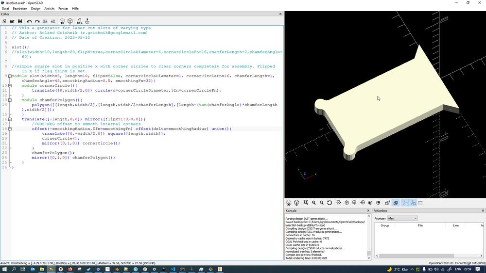
Following parameters can be set up for the slot (as module parameters):
width(standard value: 5) - width of the slotlength(standard value: 10) - length of the slotflipX(standard value: false) - whether slot should be flipped along x-axis or notcornerCircleDiameter(standard value: 1) - diameter of the clearance circles at the bottom of the slotcornerCircleFn(standard value: 16) - facet number of the clearance circles at the bottom of the slotchamferLength(standard value: 1) - length of the chamfer at the top of the slot (in y-direction, perpendicular to the slot)chamferAngle(standard value: 45) - angle of the chamfer at the top of the slotsmoothingRadius(standard value: 0.5) - smoothing radius for the transition between clearance circles and bottom/side walls of the slotsmoothingFn(standard value: 32) - facet number for the transitions between clearance circles and bottom/side walls of the slot
Here’s the local Git log for how the laserSlot generator came to be (to estimate the timeline of events):
RGR@NB3694514 MINGW64 ~/sciebo/FabAcademy/Assignments/LaserCutting/laserSlot (master)
$ git log
commit 46d7fde02c5e3bb800f7b81a2e039384bcb63767 (HEAD -> master)
Author: Roland Grichnik <r.grichnik@googlemail.com>
Date:   Sat Feb 12 15:49:01 2022 +0100

    Added slot base circle smoothing.

commit 1e1030776a3a539efd1c2d56da1ae99b280e0da5
Author: Roland Grichnik <r.grichnik@googlemail.com>
Date:   Sat Feb 12 15:16:49 2022 +0100

    Added chamfer functionality and generalized generation.

commit 73e45441a0731522f4a30eb19060068bf641b8f6
Author: Roland Grichnik <r.grichnik@googlemail.com>
Date:   Sat Feb 12 14:37:33 2022 +0100

    Initial Commit.
Dividers
Since I had my slot generator working well now, I implemented the divider generator. To that end I’d:
- Program an OpenSCAD module (
laserDividerGenerator.scad) that useslaserSlot.scadfor generating box dividers that- were variable in outer measurements (length, width, height)
- could generate and preview any number of horizontal and vertical grid separators
- outputs 2D shapes that can be exported directly as SVG or DXF and be cut
- outputs either full cut patterns (with each board being an object) or only unique boards with the number of copies to cut next to it
- (at some point in the future might generate box inserts that are not just simple grids)
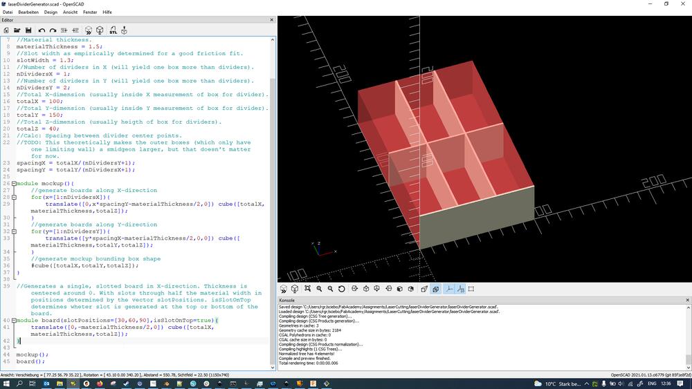
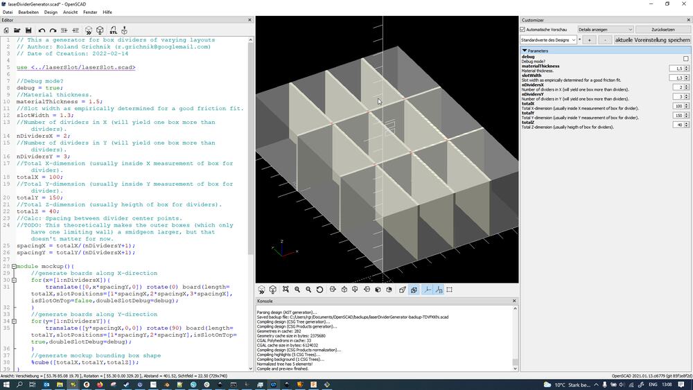
I started out by sketching out a rough mockup of what I wanted…
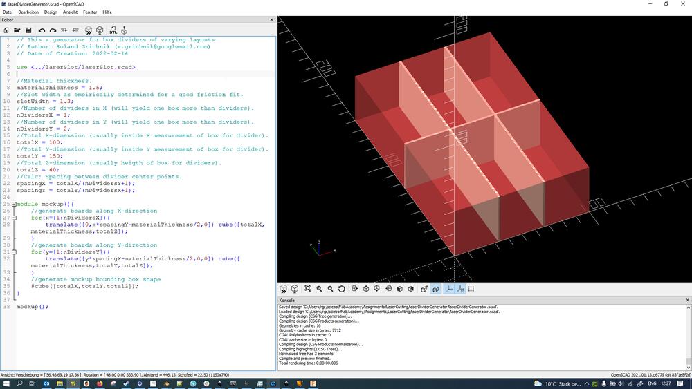
…and then starting modularization by externalizing the board generation code into a new module.
I then implemented slotting of the boards reusing the laserSlot.scad generator written earlier (note: all slots are still facing the same direction here)…
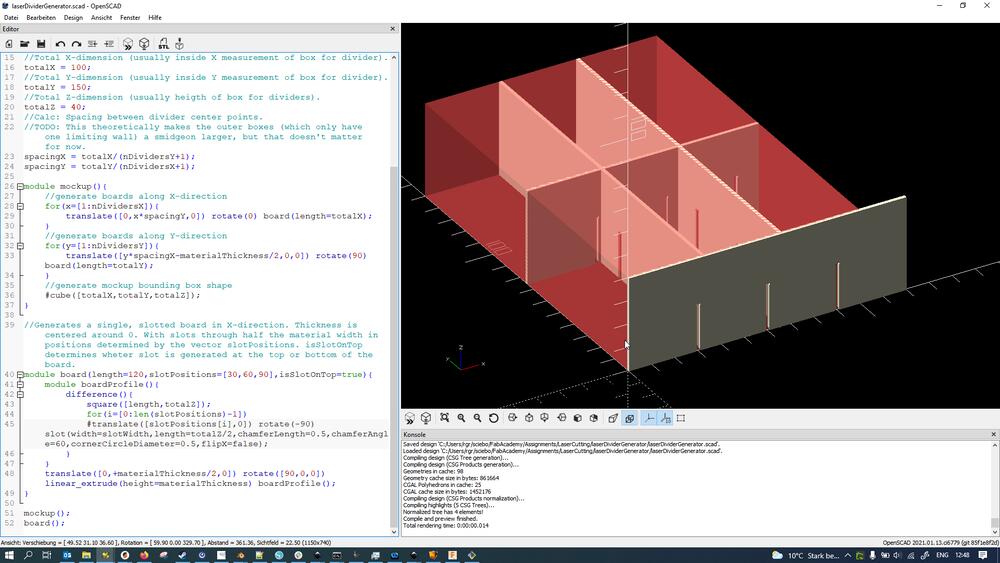
…and added the ability to flip the slots on the board.
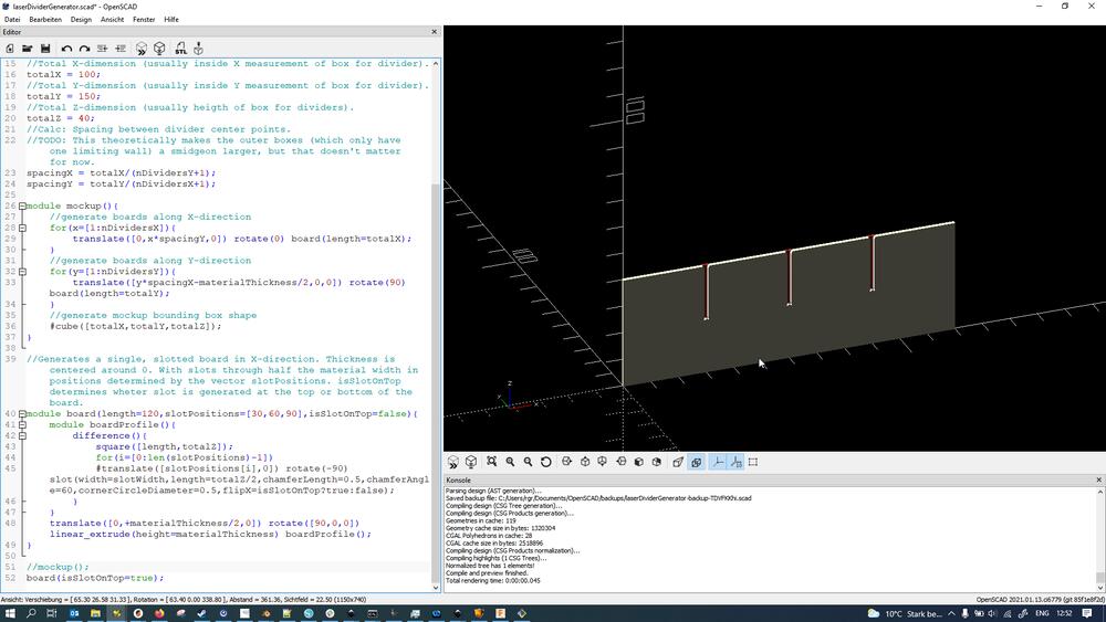
The mockup now was already showing the proper results (with slots in dividers of one direction being on top, in the other direction on the bottom)…
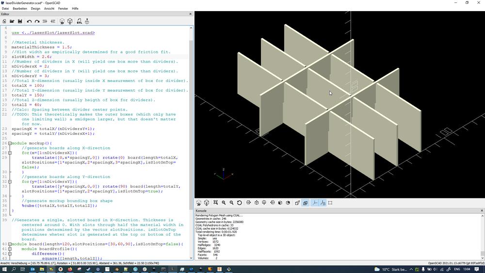
…but I decided to add another feature to visualize the bounding box of the whole thing.
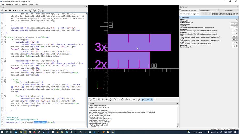
I continued by implementing a mode besides the “mockup” one for generating cut patterns only of unique boards (with the number needed printed next to it)…
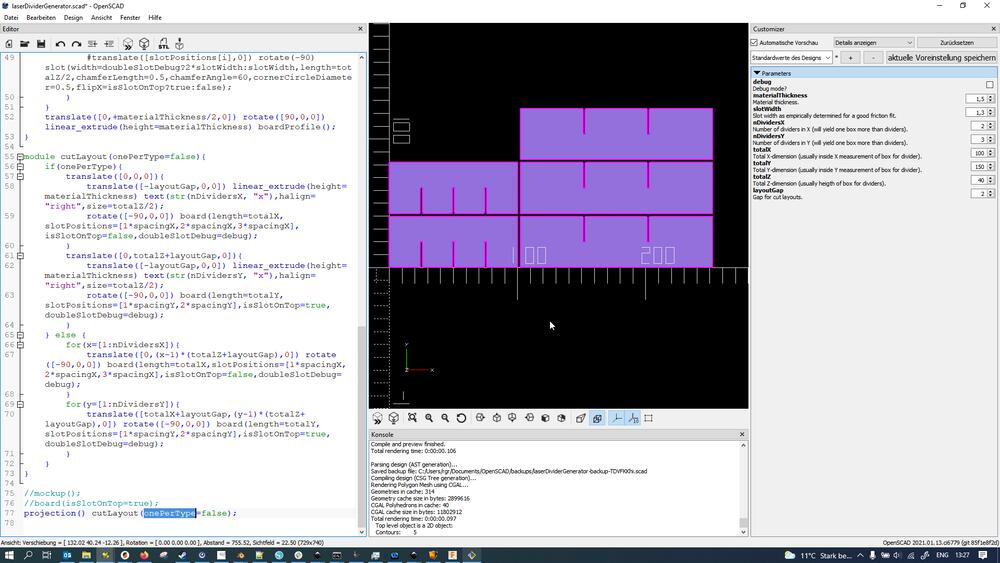
…and/or all the boards needed for the divider in one single cut pattern (though this was not in any way nested efficiently - they are just pasted next to each other).
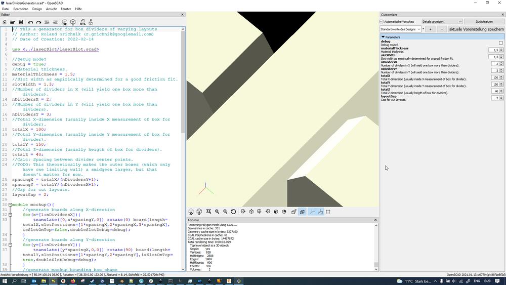
Here’s a detail of the connection of two boards showing the chamfers added to the slot for ease of assembly:
Again, here’s the local Git log for how the divider generator came to be (to estimate the timeline of events):
RGR@NB3694514 MINGW64 ~/sciebo/FabAcademy/Assignments/LaserCutting/laserDividerGenerator (master)
$ git log
commit 1f8be83096c5bdea2bd0b2f56f53cd74b8838da3 (HEAD -> master)
Author: Roland Grichnik <r.grichnik@googlemail.com>
Date:   Wed Feb 16 11:32:52 2022 +0100

    Last changes to dynamically adjust for varying number of dividers. Also added Customizer dropdown to change modes.

commit 269f5aa6c796416120b1dca09e0d87a744da1af9
Author: Roland Grichnik <r.grichnik@googlemail.com>
Date:   Mon Feb 14 14:07:20 2022 +0100

    Made debug mode not be the default case anymore.

commit 38760921e62bcfc642651e7867599ab9fb04bf4b
Author: Roland Grichnik <r.grichnik@googlemail.com>
Date:   Mon Feb 14 14:06:26 2022 +0100

    Fixed cut pattern generation by adding kerf offset compensation.

commit 3ef0ddc5f070ac71f0659ef81fd339650d235c92
Author: Roland Grichnik <r.grichnik@googlemail.com>
Date:   Mon Feb 14 13:34:19 2022 +0100

    Added cut pattern layout generation.

commit 368ccfb506ddf41d5409f7c7303f1068215681e2
Author: Roland Grichnik <r.grichnik@googlemail.com>
Date:   Mon Feb 14 13:11:07 2022 +0100

    Generator working without slot position autogeneration yet (TODO).

commit bd906f7ecc71920e210443e5cda29fd11a57dd84
Author: Roland Grichnik <r.grichnik@googlemail.com>
Date:   Mon Feb 14 12:52:58 2022 +0100

    Added ability to flip slots to top.

commit 3c43492989ea156448ef6265beec12b1143c0d1c
Author: Roland Grichnik <r.grichnik@googlemail.com>
Date:   Mon Feb 14 12:48:54 2022 +0100

    Fully fleshed out board generation with proper slots.

commit 85405784dda7359f13d4e74111fbabe9d737cb1f
Author: Roland Grichnik <r.grichnik@googlemail.com>
Date:   Mon Feb 14 12:39:02 2022 +0100

    Modularized code for board generation.

commit 5b727c76ddabfefe71636af2ea376bac8306009a
Author: Roland Grichnik <r.grichnik@googlemail.com>
Date:   Mon Feb 14 12:28:52 2022 +0100

    Initial commit.
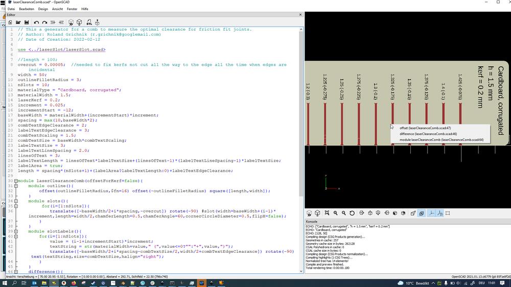
Comb
I also made a laser comb generator so I could quickly iterate through different materials and/or clearance settings:
- Program an OpenSCAD module (
laserClearanceComb.scad) that useslaserSlot.scadfor generating clearance combs that- can produce any number of slots on a test piece
- varies slot size incrementally (where starting point and increment can be chosen) to allow for testing fit
- contains a text label field with key information about the test sample
- outputs 2D shapes that can be exported directly as SVG or DXF and be cut (to an extent, since there is a mix of features to be cut - slots - and features to be engraved - text - this does take a tiny bit of manual manipulation before sending to the cutter - but not too much…)
Here’s a shot of the final generator (I won’t go into detail about the whole process on this one):
And, again, a git log to show how the file developed:
RGR@NB3694514 MINGW64 ~/sciebo/FabAcademy/Assignments/LaserCutting/laserClearanceComb (master)
$ git log
commit 22c86c673bb195b97b375d941d342c40631b73b0 (HEAD -> master)
Author: Roland Grichnik <r.grichnik@googlemail.com>
Date:   Wed Feb 16 12:07:22 2022 +0100

    Last small changes, mainly to accommodate for more decimal places in the Customizer and fixed text scaling.

commit 149ef417fdc1a5002bbeeab164b9a1207135974d
Author: Roland Grichnik <r.grichnik@googlemail.com>
Date:   Mon Feb 14 00:53:17 2022 +0100

    Changed base size and form slightly.

commit ae952fe5eaef04b3990e4454dda74d921ca798dd
Author: Roland Grichnik <r.grichnik@googlemail.com>
Date:   Mon Feb 14 00:18:52 2022 +0100

    Removed exemplary SVG from tracking.

commit 19e71dc731ae8f6f3556afcb9258129e8b9b9855
Author: Roland Grichnik <r.grichnik@googlemail.com>
Date:   Mon Feb 14 00:17:41 2022 +0100

    Modularized code more, added kerf compensation.

commit f9162a8fe542fbcc5e226be564ba935092fd43e0
Author: Roland Grichnik <r.grichnik@googlemail.com>
Date:   Sun Feb 13 23:42:18 2022 +0100

    Removed kerf from comb generation logic, fixed sometimes incomplete cutting, modularized code.

commit 2ff45bbdb8bdc7da51c276dcf49720af44d71583
Author: Roland Grichnik <r.grichnik@googlemail.com>
Date:   Sun Feb 13 21:13:22 2022 +0100

    Cleaned up comb generation.

commit 4c0ef5cc7db0537feb21b8012a102ca655b808f8
Author: Roland Grichnik <r.grichnik@googlemail.com>
Date:   Sun Feb 13 12:17:58 2022 +0100

    Added Outline Filleting.

commit 221a23946af81dd7ddabbf5ef48270092a73fde6
Author: Roland Grichnik <r.grichnik@googlemail.com>
Date:   Sun Feb 13 12:14:43 2022 +0100

    Added label field.

commit daceebc743aab2999c0271ef5799410183bab09a
Author: Roland Grichnik <r.grichnik@googlemail.com>
Date:   Sun Feb 13 11:47:09 2022 +0100

    Initial commit.
Using the Tools to Make a Box Divider
Once all my tools were in working order, I set out to test build a simple box divider. The clearance testing for my material went into the group assignment part. After finding out a good joint clearance, I then prepared the cut files for my box divider by running the generator for a box divider of size 100 x 120 mm with 2 x 3 dividers. The SVG output from OpenSCAD was taken into Inkscape to merely split the two unique boards apart, then the needed parts were placed in Visicut (more details on the workflow found in the group assignment page). Since I was working with cardboard envelopes with a certain geometry, I placed the parts so the would wit onto the envelope:
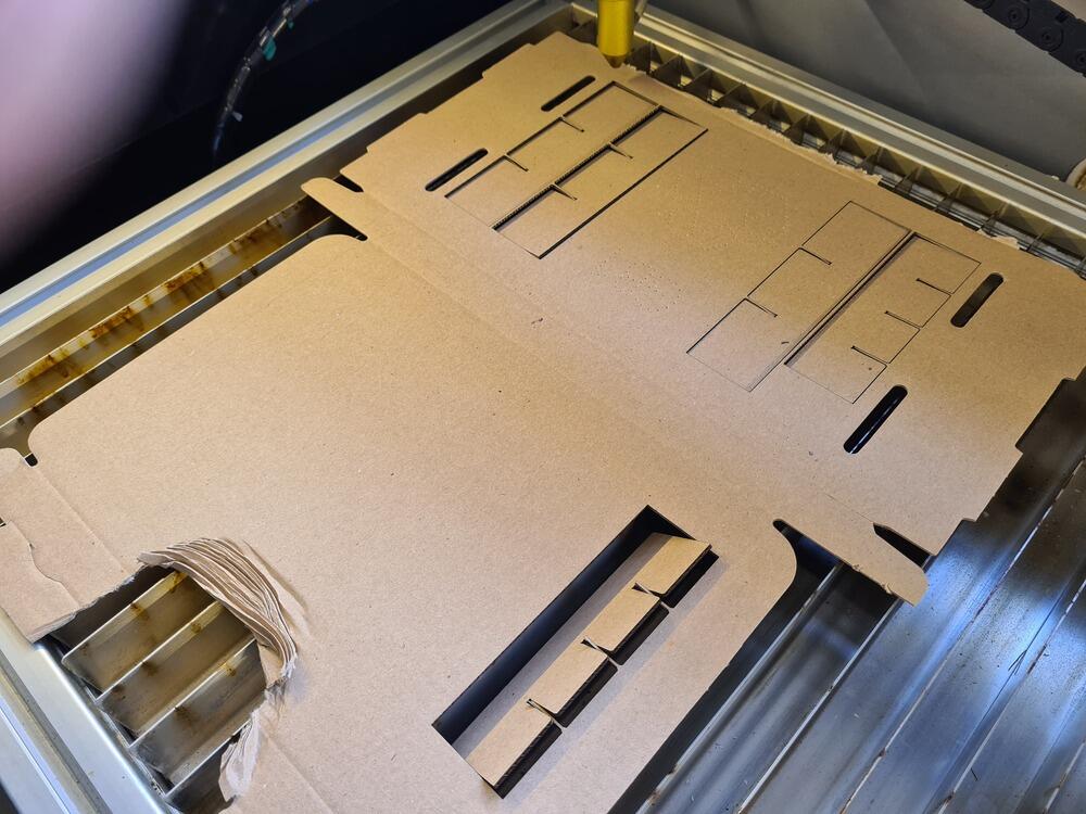
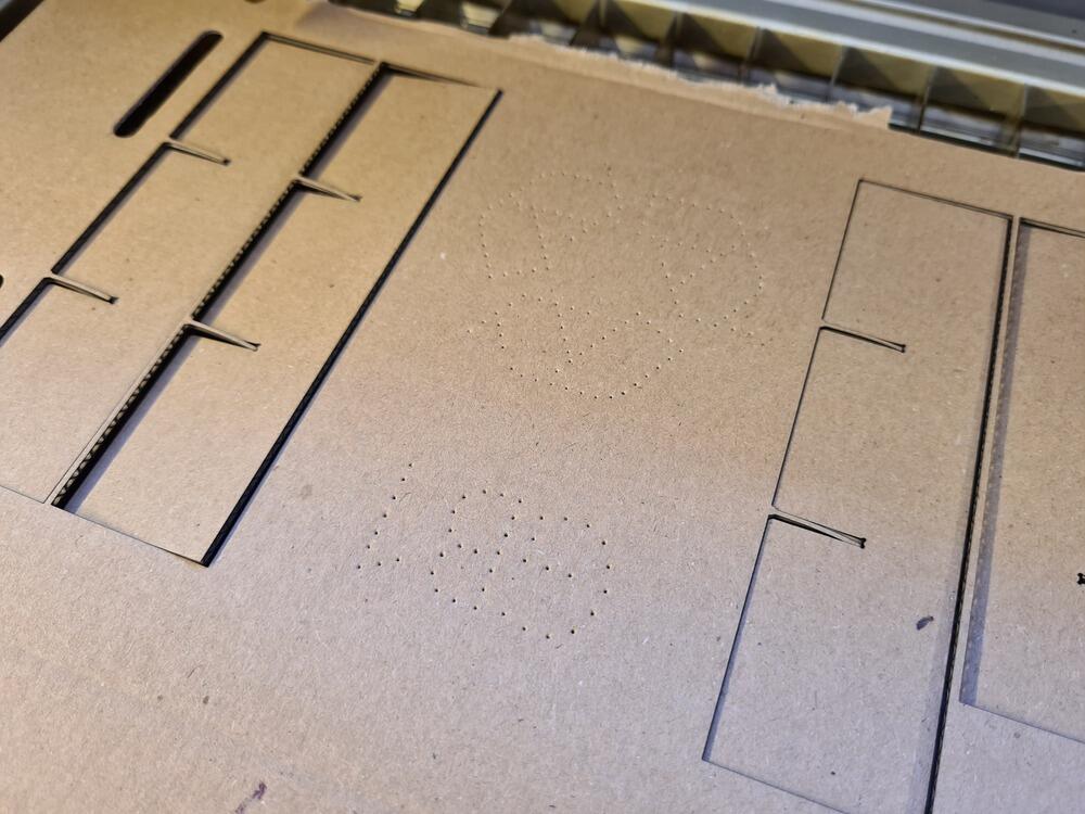
I also took care to avoid the center of the envelope as there was a pattern marked into there:
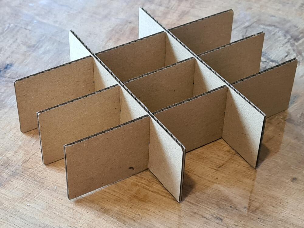
I then went on to assemble the parts into the divider, which worked very well and produced a nice friction fit between parts, as had been established using the clearance comb:
To emphasize the generalization aspect, I also used the same generator setup with other material parameters for 5.72 mm thick 3-ply plywood (the clearance fit had been established earlier with a comb, too). This also assembled well and the friction was satisfactory (shown here with one part missing though… thanks, offspring :D… ):
I am happy with the output of this week. Even though I didn’t have too much time to tinker with other aspects of the laser cutter, like engraving - which I have done in the past already, though, just not as methodical. More in a “christmas presents need to be finished yesterday, hurr-durr, kind of way” :) …
I feel like programming the features to the detail presented not only helped me understand better what the features need, but also gave me and our lab useful little tools to reuse. Nothing fancy, but I call it a success.
Design Files
- vinyl sticker design file (SVG, Inkscape)
- openSCAD source code (without Git history):
- clearance comb vector files:
-
“Moment”: Februar-March, packing up a big household unfortunately doesn’t happen in a day :) ↩