6. 3D Scanning and printing
Group Work
A detailed documentation of our group assignment work can be found on the shared group assignment webpage.
Background - 3D Scanning and printing
-
3D-Printing:
- First printer: Prusa i3 Mark 2 (FDM Printer) (Upgrade path: Prusa i3 Mark 2 -> Prusa i3 Mark 2.5s -> Prusa i3 Mark2.5s with MMU2)
- Second printer: Creality Ender 3 (v1) (FDM Printer) (Upgrade Path: self-printed upgrades, pre-tensioned bed springs, nothing else needed)
- Third printer: Anycubic Photon (LCD UV Resin Printer) (Upgrade Path: chamber heater with thermostat, case exhaust)
- Accessories: MMU2 (Multi-Material Unit) for Prusa i3 Mk2.5s, Cleaning and Curing Station for Anycubic Photon
-
3D Scanning:
- First efforts: DAVID LaserScanner, didn’t go far though because quality was lacking too much for what I wanted
- Then: Photogrammetry using Visual SFM and meshing in MeshLab - this was getting where I wanted it to be, yet still needed to much manual intervention and a very powerful machine to run it
- Lately: Photogrammetry using Meshroom - at this point in time, photogrammetry has become essentially a drag-and-drop affair and is even able to capture small details if done right
3D Scanning
For learning about 3D-scanning, we actually visited out hosting sister FabLab in Kamp-Lintfort, Germany, as our own little FabLab in Kleve does not have a 3D-scanning setup yet. Ahmed Abdellatif gave us a very nice rundown of what’s involved in using the EinScan-Pro+ 3D-Scanner they have down there.
EinScan-Pro+
- EinScan-Pro+ is a handheld and/or stationary structured light scanner
- We also had the turntable available to use
- We began by calibrating the scanner using the scanner’s software EinScan Pro 3.1.0.4
- We first attached the texture capture camera to the scanner - this is used to capture the color information - a.k.a. texture.
- We then ran the calibration. To that end, a calibration plate that comes with the scanner was scanned in different orientations following the on-screen instructions until calibration was sufficient. The scanner had to be moved and rotated in different ways seeing the calibration plate, until sufficient.
- We then continued to scan objects using the turntable:
- The object(s) to be scanned were placed on the turntable
- Then in the scanning software, the number of steps to scan per rotation was given
- For my own object, I started with 4 scans (i.e. 90° steps) to get a rough overview over the object. Since this was a small tabletop/board game figurine, the markers on the turntable were always visible and I used the registration marks omn the turntable to align and register sequential prints.
- After doing a full rough rotation, I had the software scan 10 steps of the object standing up, again - this was to increase any detail that might still be missing around the object.
- To fill out more detail, I then laid the figurine on both its back and its front and repeated the same process to add more detail from different points of view.
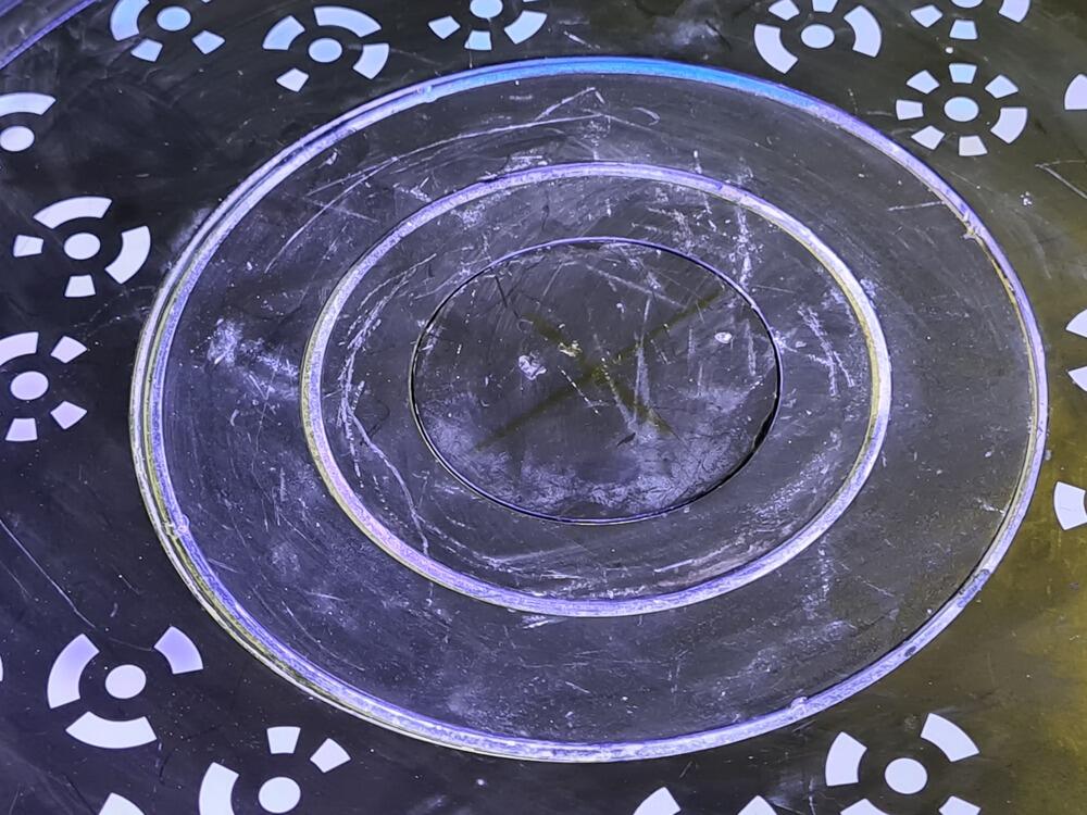
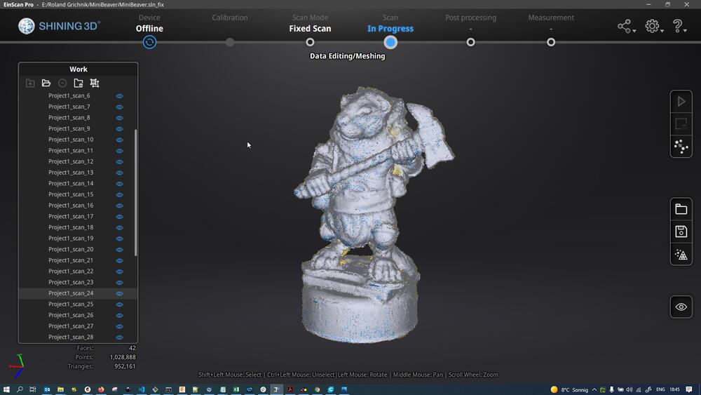
This is the EinScan Pro’s turntable, with the (shaded) centering cross barely visible at the middle of the turntable:
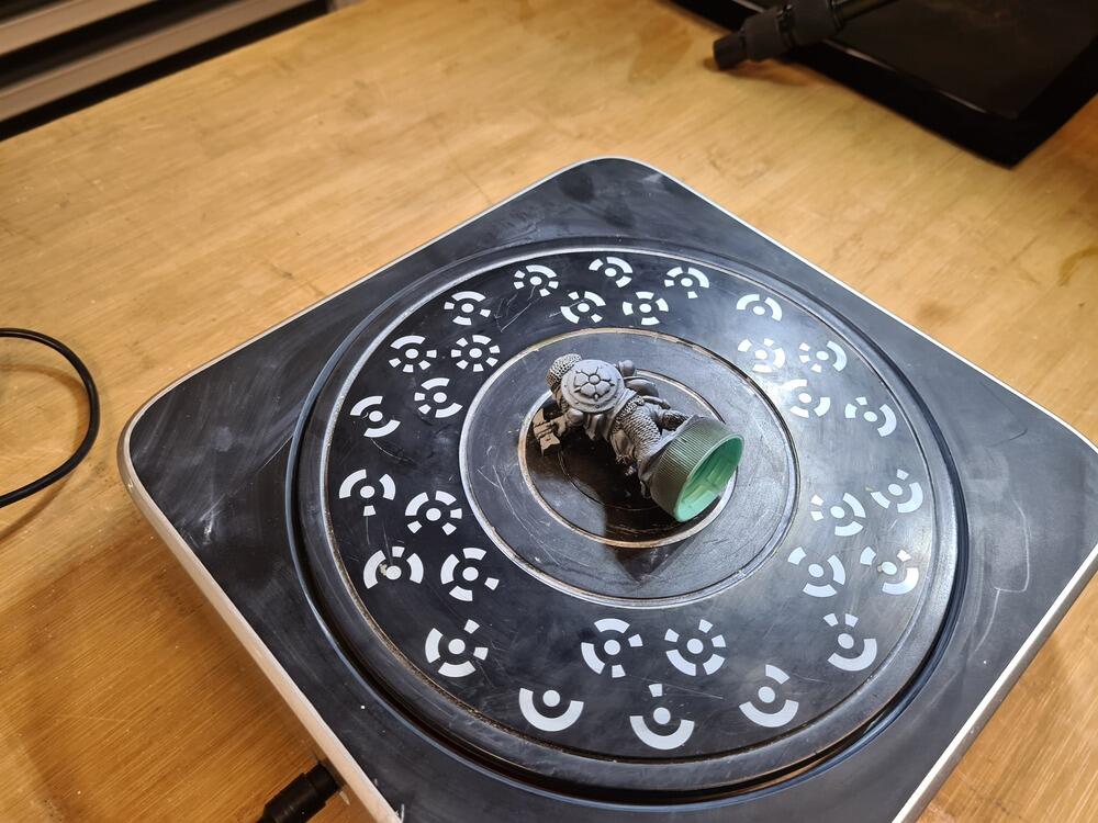
Turntable with the object to be scanned (Beaver figurine) lying on its belly…
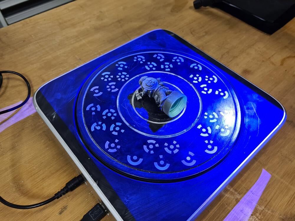
…and what it looks like when scanning (with the illumination on):
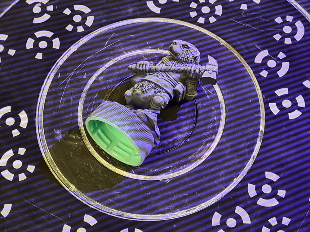
The scanned object showing the structured light pattern used by the scanner for the scan (the stripe pattern varies width during the scanning process):
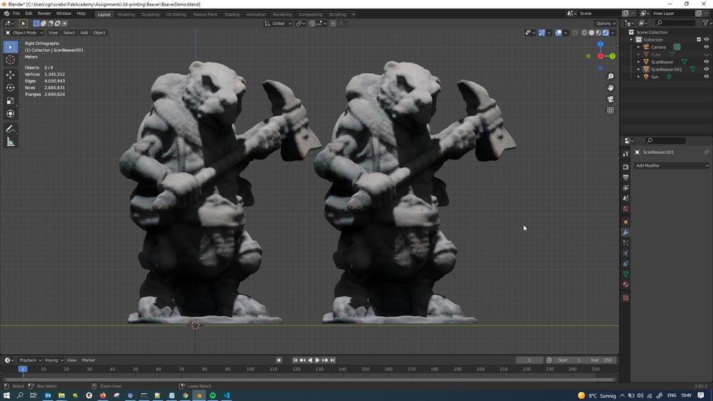
After doing standing, lying on its face and lying on its back scans, the full point cloud was meshed at high resolution to arrive at following high-res mesh:
3D Printing
With the scanning assignment in the bag, I turned to 3D-printing. Since we have a number of very different 3D-printers accessible in the lab, we ran them through a few unified tests to compare them. These efforts can be found on the group assignment page. The printers produced quite some different results in all of the tests. The tests reinforced what I had already learned over my time of dealing with 3D-printers at home:
- A good 3D-print starts at the design stage. Objects not designed for 3D-printing specifically usually don’t make good, functional prints.
- Overhangs should be kept at a minimum where possible. Sharp overhangs are to be avoided completely. A maximum angle of 45° should be kept wherever possible. Naturally, this means that the print orientation needs to be clear from the beginning of the design phase.
- Printing at low layer heights can result in pretty smooth prints, but even when printed at high resolution/low layer height, I wouldn’t want to print a decorative item that way. Functional prints all the way!
- Printing with adaptive layer height can produce rather smooth prints without too much time impact (by limiting small layer heights to surfaces where a lot of stepping could be seen otherwise, e.g. tops of curved surfaces).
- Supports should be avoided wherever possible, as they either can leave marks or (if they don’t), are pretty expensive material-wise (I’m looking at you, PVA…).
- Not all printers are equal. Not all print setups are equal. Not all slicer settings are equal. If you have found settings that work for you and that you can estimate needed clearances for well, stick with it!
All following prints were done on my personal Creality Ender 3, which is very similar in build to the Ender 3 v2 we have available in the lab. The filament used was a German filament made by manufacturer OWL-Filament, which produces budget filament with a nice gamble factor - some batches are downright unusable. Still, good value for the money.
Printing the 3D-Scan
I decided to start by printing the model I scanned earlier. Due to the model being a commercial model and me not owning any rights to it, I will not make the STL file or the scan files public to honor the owners of the copyright. To ease the burden on the slicer, I decided to remove some of the mesh vertices first - there really is no need to print the mesh at full resolution, as this would not be recognizable in the FDM-3D-print anyways.
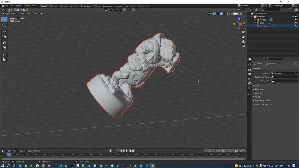
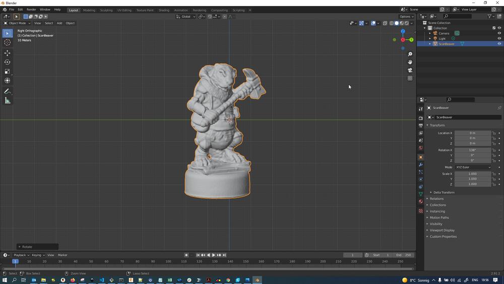
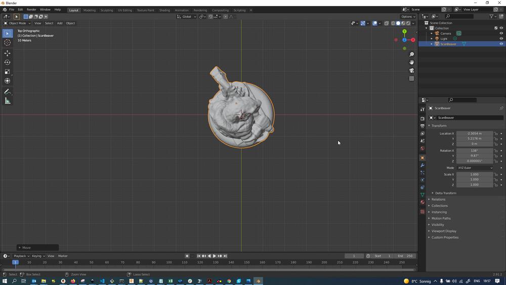
I first imported the OBJ-file of the high-res mesh of the beaver model into Blender. This usually ends up somewhere floating in space:
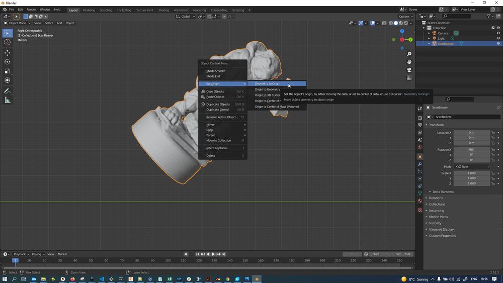
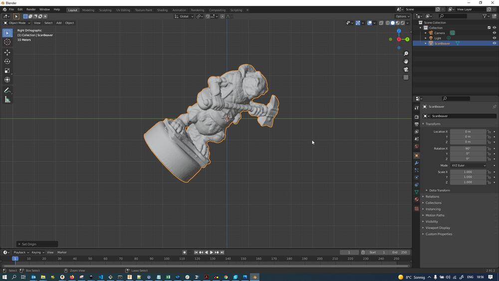
Using Right Click -> Geometry to Origin, the mesh can be quickly relocated to the file origin:
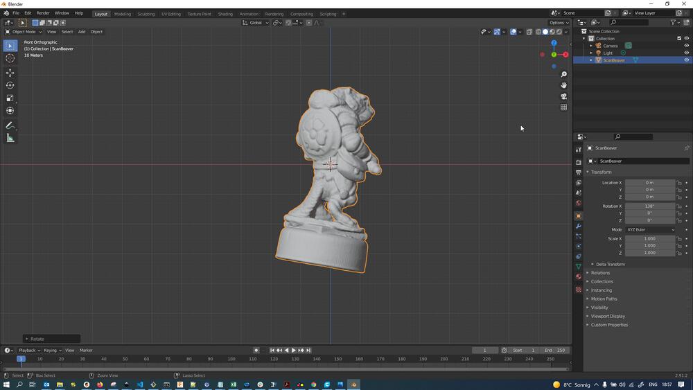
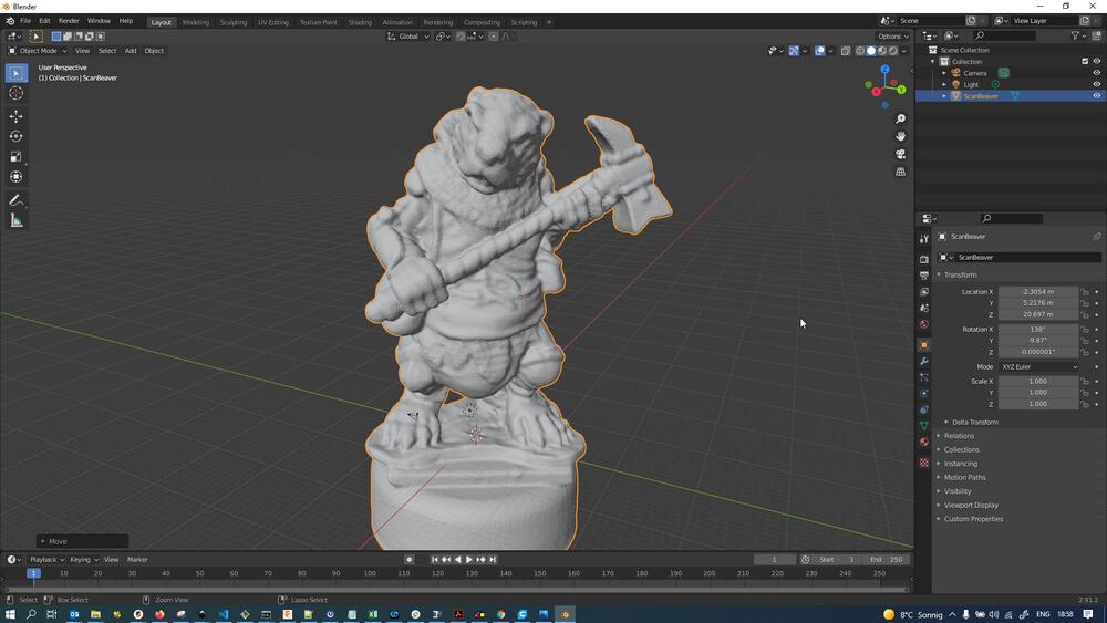
After pressing NumPad 1 to go into frontal view, we see the mesh is also rotated…
…which can easily be fixed by pressing R and rotating using the mouse until straight:
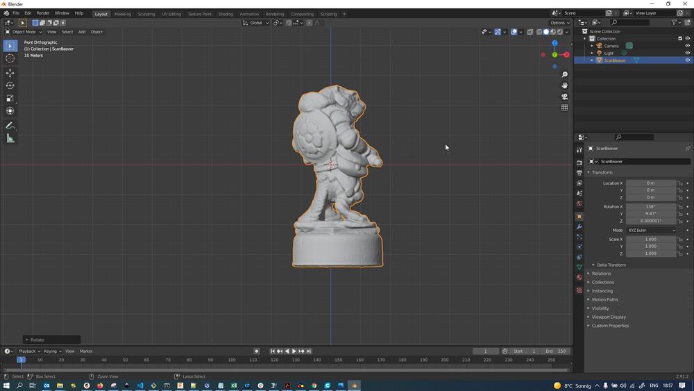
Pressing NumPad 3 to change into side view, we notice the mesh is also rotated in this axis, which again…
…can easily be fixed by pressing R and rotating using the mouse until straight:
Pressing NumPad 7 we change into top down view, where we can see the mesh is not exactly centered from above (we want to center the bottle cap)…
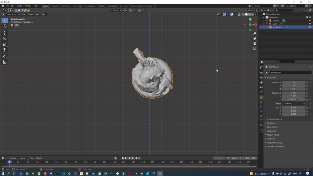
…which can be fixed by grabbing the mesh using G and moving it until pleased:
I then also grabbed the mesh using G and moved it up on the Z-axis (movement can be constrained after grabbing by pressing the axis’ key, in this case Z) until pleased:
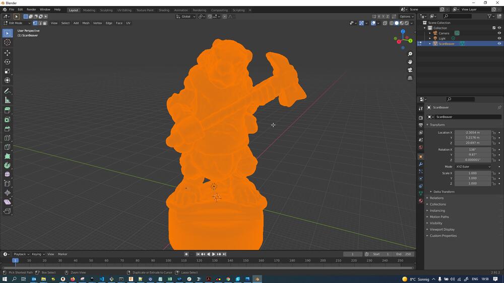
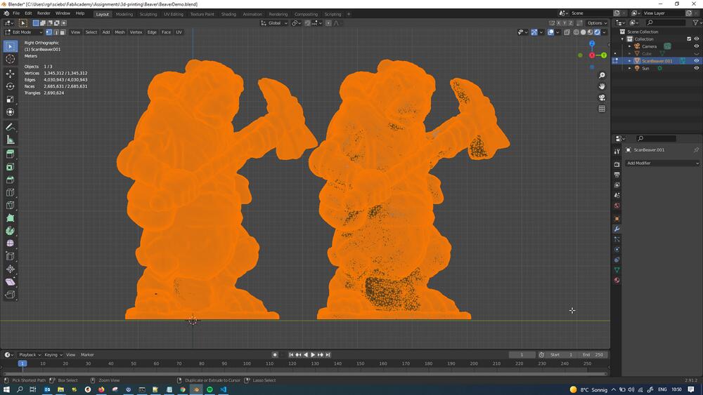
In mesh edit mode (press Tab to open) we can see that the mesh is super dense - we can’t even see single vertices really:
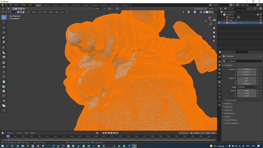
Rotating the view by pressing MMB we can see that the mesh is way less dense from underneath - a consequence of there being way less scans done from the underside earlier:
I then created a cube (Shift + A -> Mesh -> Cube), scaled it by pressing S and then moved it in Z using the grab key G -> Z until pleased with how the cube overlapped the bottle cap to be removed:
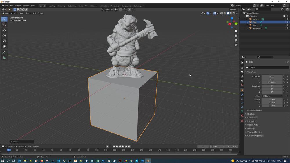
I then added a Boolean Modifier to the Beaver Mesh and set the object to be subtracted to be the cube created earlier:
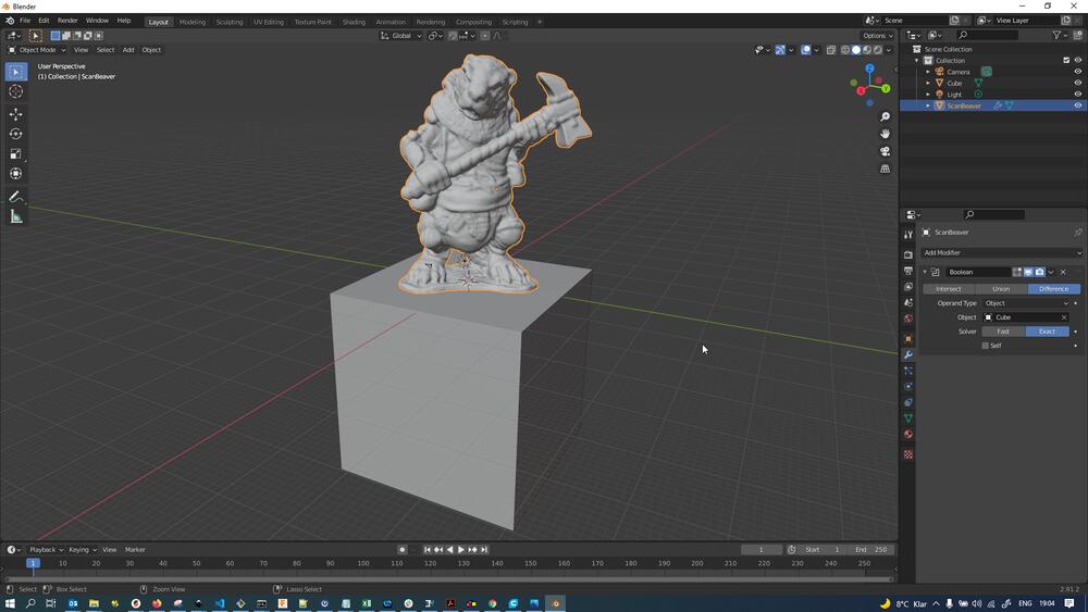
After applying the modifier for good by pressing the dropdown next to the little camera icon and hitting Apply, the cube is subtracted from the mesh for good:
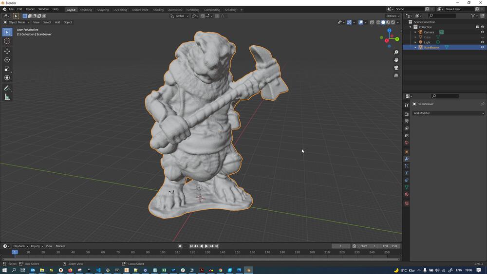
Here is another shot of the resulting mesh after switching to Rendered viewport shading (using the Eevee renderer), removing the original Light object, adding a Sun light using Shift + A -> Light -> Sun and rotating the sun light slightly until I liked the shadows:

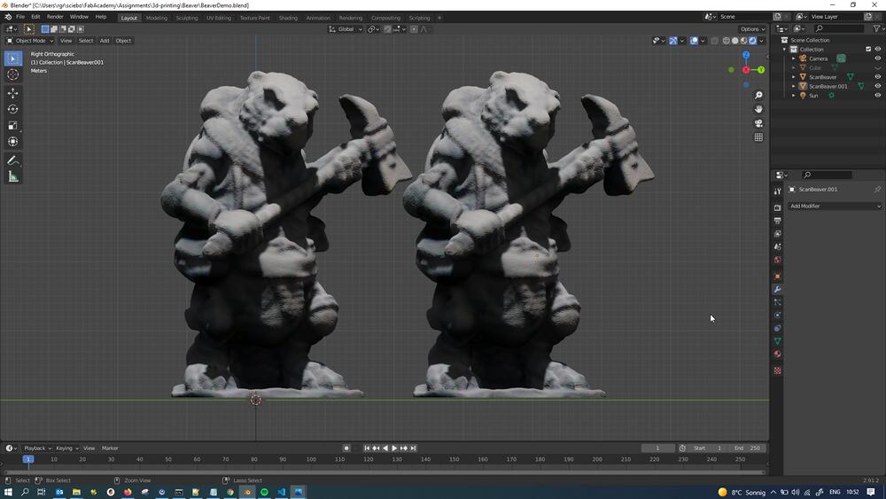
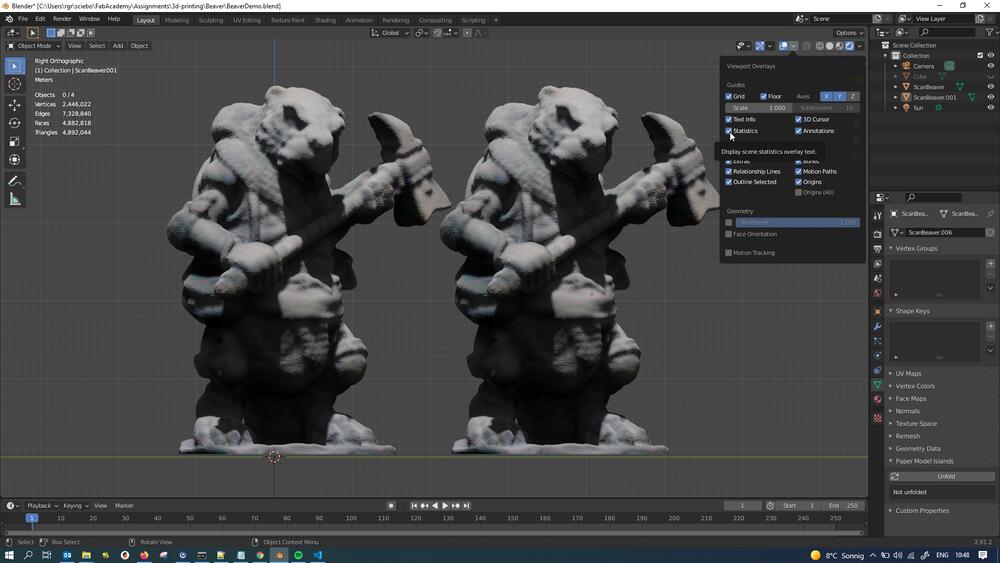
I then set out to decimate the high density mesh to get something more workable (since high res meshes can be really painful to work with). Since I wanted to compare different mesh densities, I decided to create copies of the beaver. To that end, I duplicated the mesh and immediately moved it over 35 units on the y-axis by pressing Shift + D -> Y -> 35:
For being able to see our efforts in mesh decimation later, we need to switch on mesh statistics in the Blender viewport (statistics can already be seen in the top left of the viewport):
I then added a Decimate mpdifier to the beaver mesh:
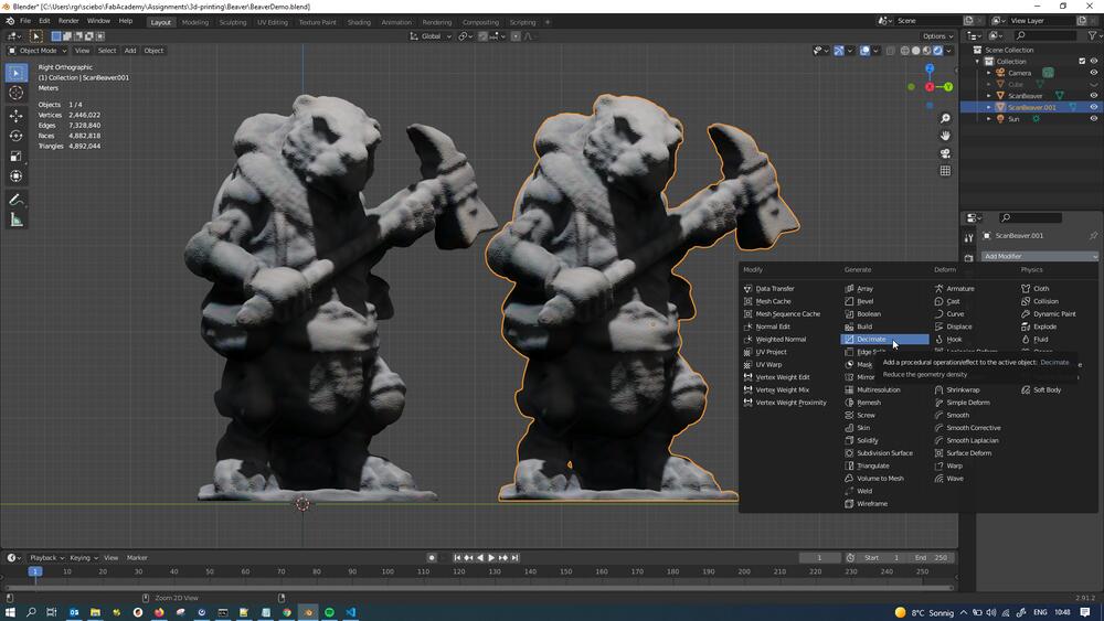
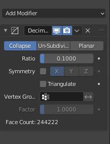
The decimation was set to following parameters: Collapse and a ratio of 0.1, meaning that edges would be collapsed until the mesh only contained 10% of the original vertices:
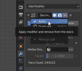
Like the Boolean modifier earlier, the Decimate modifier also has to beapplied to actually change the mesh for good:
After decimation, not much can be seen in comparison - the decimated mesh is still plenty dense:
For comparison, I joined both meshes by selecting them and pressing Ctrl + J, then going into edit mode using Tab. Here we can see in direct comparison that the right mesh is way less dense (10%, after all):
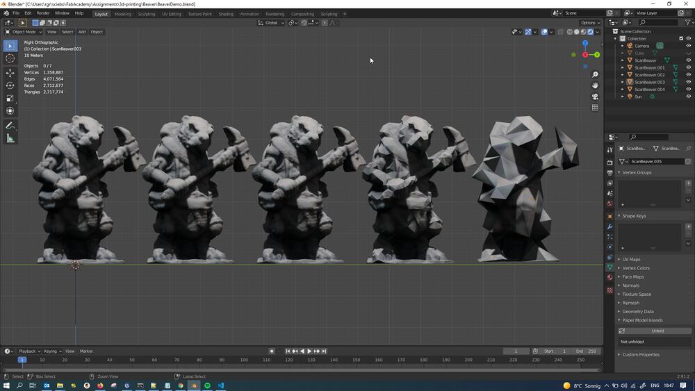
I then proceeded by subsequently decimating the meshes further, doing 10% decimation every time. The following picture shows 5 levels of detail: 100%, 10%, 1%, 0.1%, 0.01%. Even 1% still looks plenty dense to be printed at that level of detail, 0.1% looks like something you could put into a digital board game, while 0.01% is borderline recognizable:
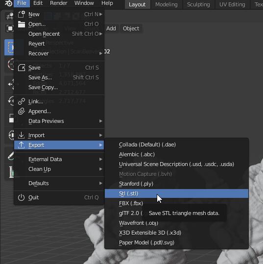
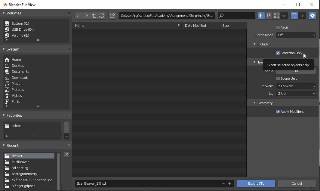
The chosen mesh (I decided for 1% density) was then selected and exported by pressing File -> Export -> STL:
For settings, give it a name and tick the box Selection Only to ignore the other meshes in the file:
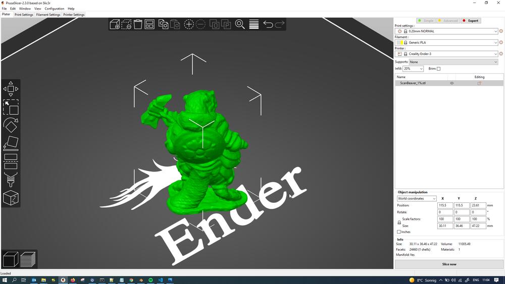
Subsequently, I opened PrusaSlicer 2.3.0 to be greeted with following screen, showing the build platform of my Ender 3 3D-printer:
![]()
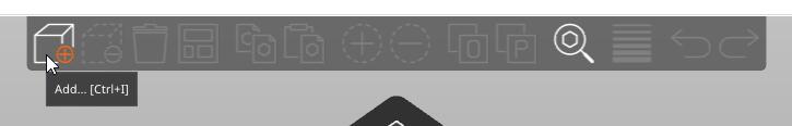
Top add objects for printing, press Add in the top menu bar and select the STL file to be added in the menu pop up:
This is the 1% density beaver on the build platform. Notice that The print automatically gets dropped down onto the build platform, even when in Blender, the foot plane might have been a little above Z0:
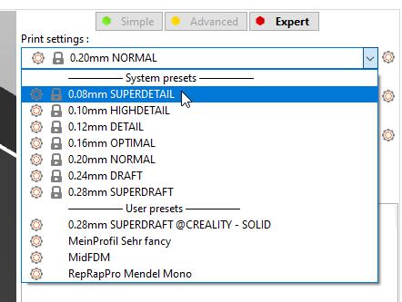
In the top right of the screen, I selected the print settings. I wanted high detail, so I selected the preset called 0.08mm SUPERDETAIL:
After pressing Slice now in the bottom right of the screen, the sliced preview automatically comes up:
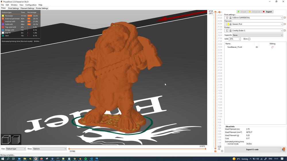
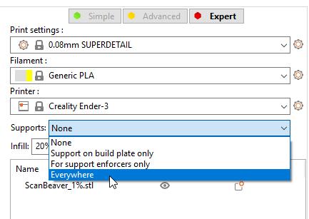
We can see that the slices look plenty fine - much finer wouldn’t be possible on this printer anyways - but we can also see that a few areas (like the hammer handle and the hammer head, the groin area) would be unsupported and more or less printing in mid air. To support those areas, I turned on supports using the dropdown in the top right again:
Here is a preview of the sliced beaver model with supports, more or less encasing the model in lightweight, removable support structures:
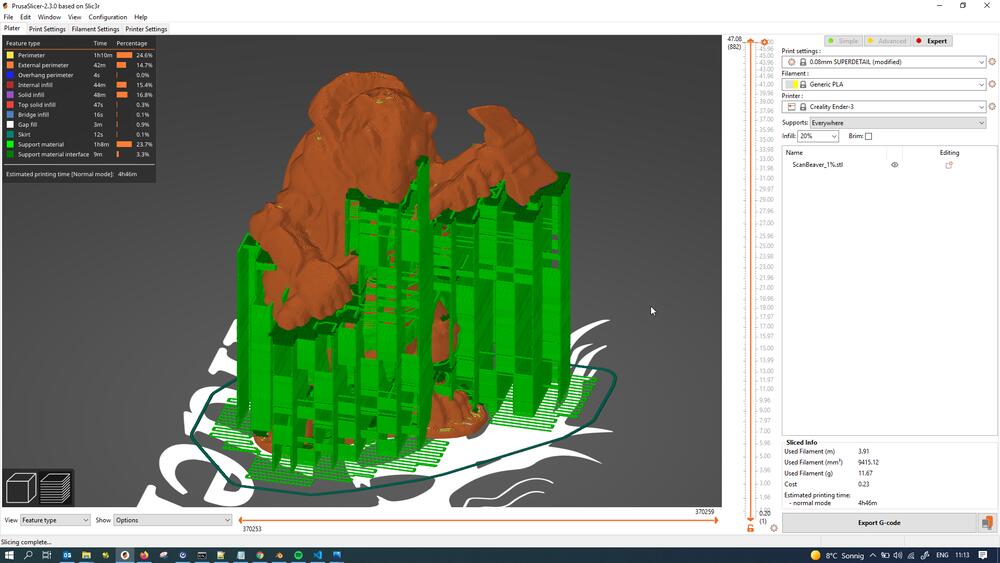
If we use the layer slider right next to the preview window, we can look inside the model and see that the supports don’t actually touch the model laterally at all - we’re going to have to trust the algorithms at work here :)…
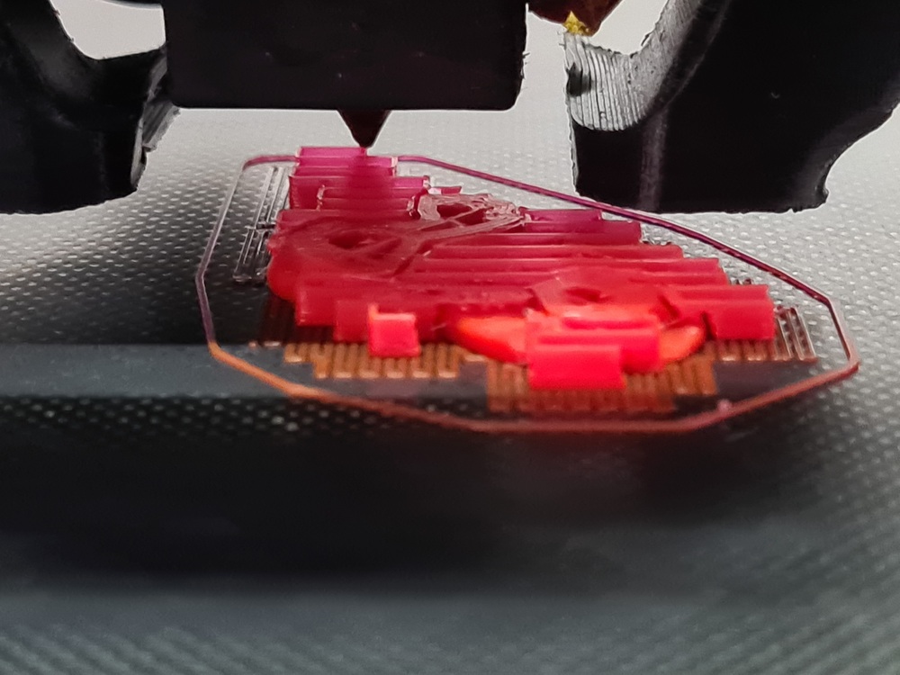
After exporting the Gcode to my Ender 3’s µSD-Card and plugging the card into the printer, I started the print. Her’s the beaver after a few layers…
…and here it is fully finished, still sitting on the build plate:
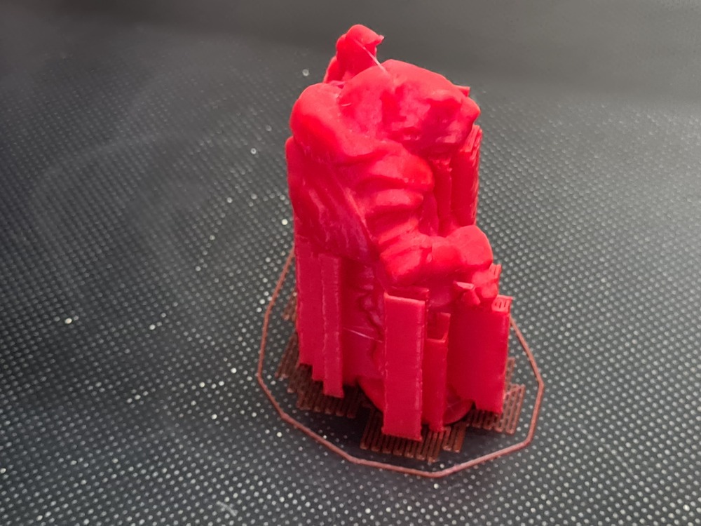
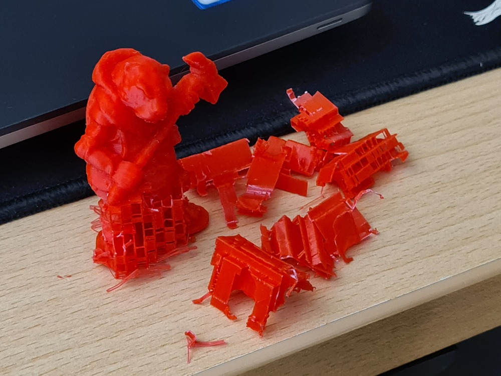
After removing it from the build plate (no tools needed, this did just come off after bed cooling), I started removing the supports using tweezers - needle nose pliers also work very well. Supports really like to be twisted off instead of just pulling, to get rid of all of them:
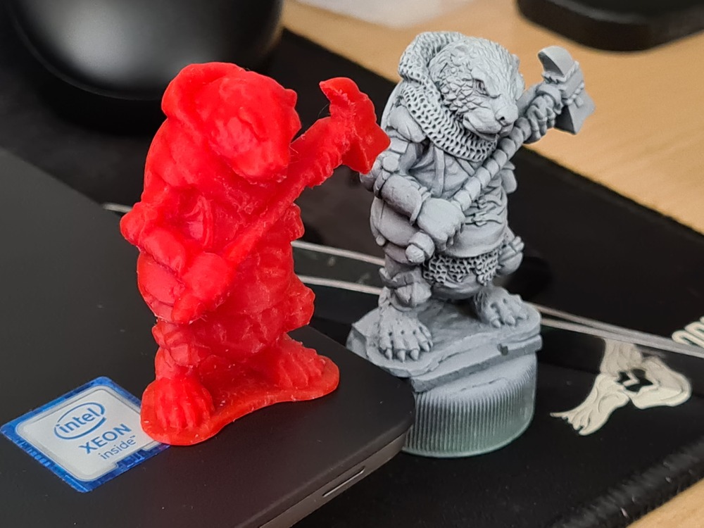
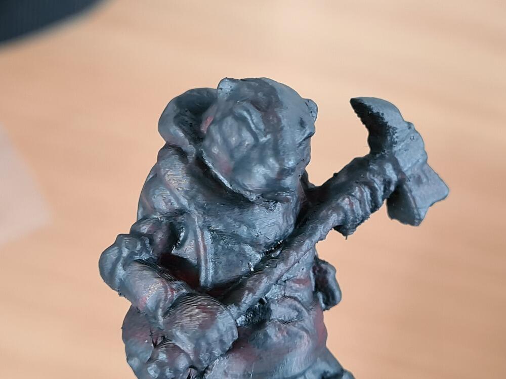
Here is the printed beaver next to the original that was scanned. It is pretty hard to make out details, since the filament is pretty translucent:
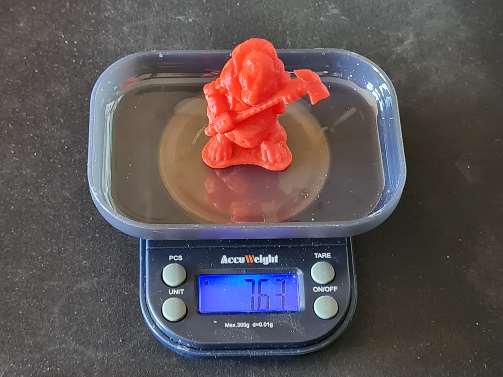
The beaver model itself turned out to weigh 7.63 grams…
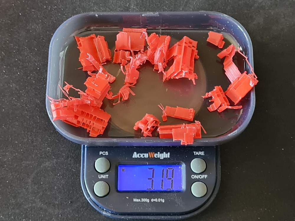
…while the supports weighed 3.19 grams. Summed up, the 10.82 grams are a little less than the 11.67 grams the slicer estimated. THis might be due to the filament density not being set up precisely for that very filament or me losing little bits of support during removal - but it’s for sure good enough for an estimate.
I then decided to give the beaver a brush on coat of Vallejo Surface Primer German Panzer Grey - RAL7021, which dries really thin and takes away the filament gloss and translucency, so details can be judged better. Not too shabby for a quick scan!
Designing and Printing an (Almost) Impossible Object
For the next assignment task, I designed and printed an object that would be very hard (or impossible) to make subtractively. I chose to make an object that would look like it’d have to topple over, yet be printed in one, single piece. Material inside the model would be distributed in a way such as to shift center of gravity (CoG) so that it would be above the footprint of the object, thus making it stand without toppling over.
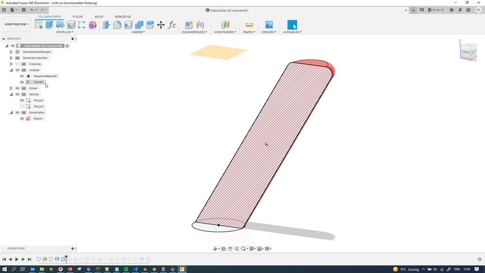
Here’s an overview of what the object’s exterior looked in the end…
…and a section view revealing the internals (the void internally would be filled with coins during printing later):
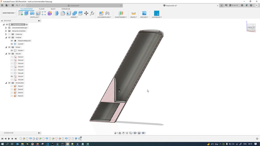
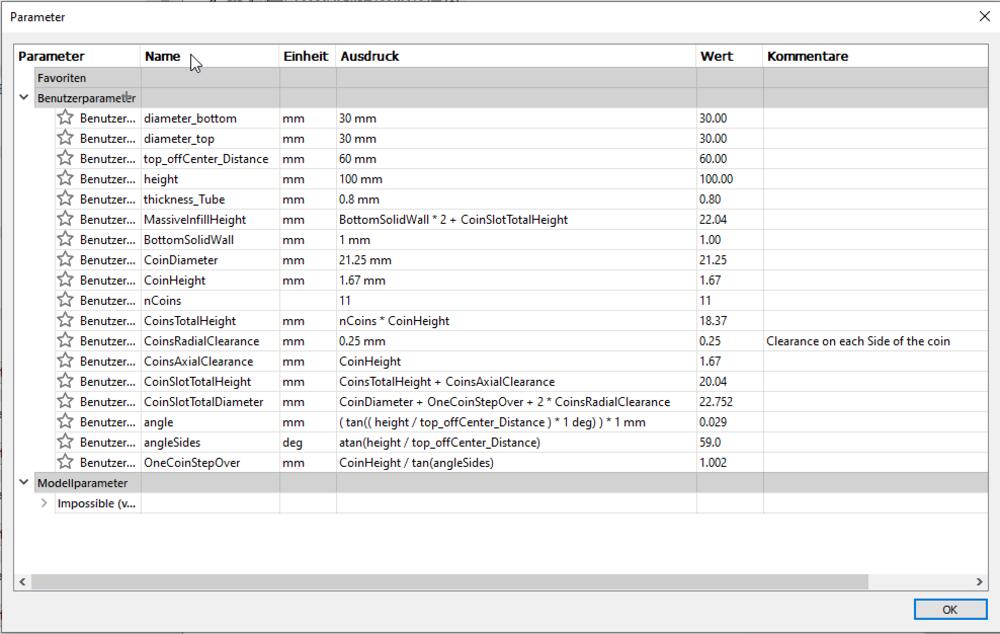
The whole object was created parametrically to facilitate late changes to its shape (and to keep good practice, in general):
This is the (short) timeline of the completed object, which I will roll back for demonstration purposes in the following screenshots:

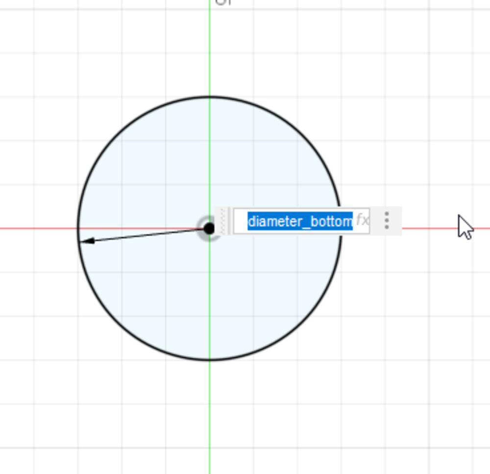
I started out by sketching a base circle onto the XY-plane…
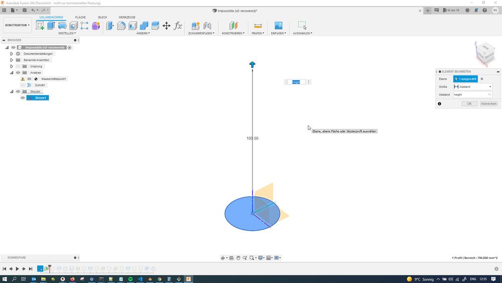
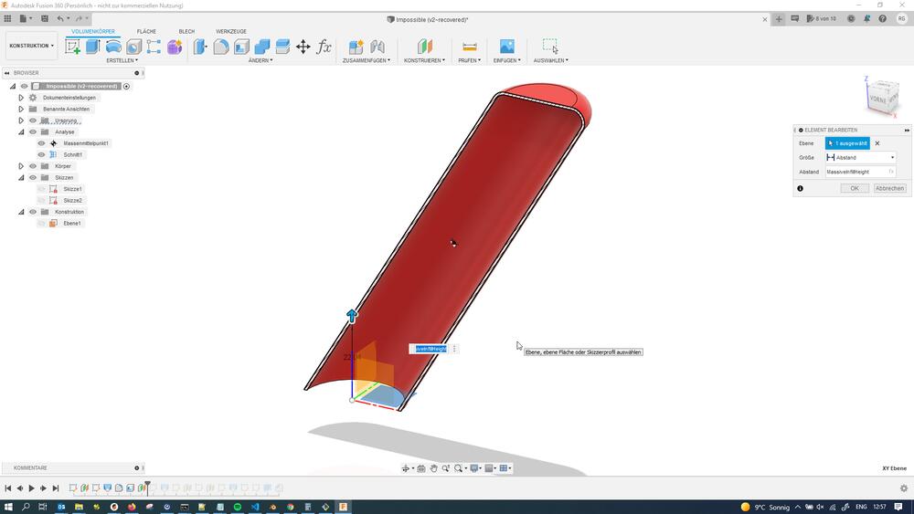
…and then created a helper plane at the target height:
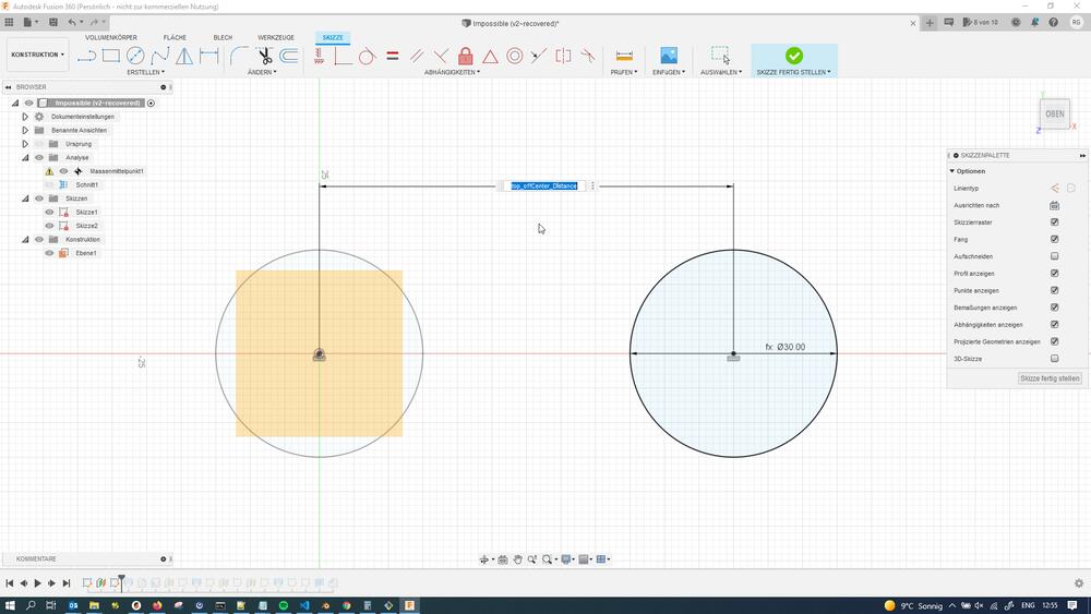
Onto the top target plane, I created a sketch with a circle for the top shape…
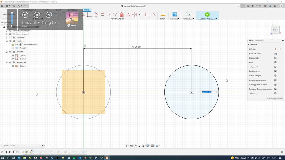
…that was off-centered from the base footprint circle for a certain amount (to create the overhang illusion):
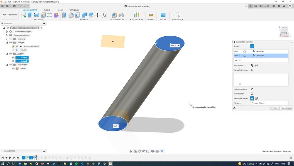
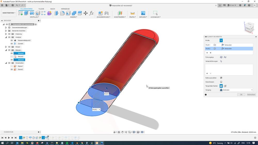
I then created a lof feature connecting bottom and top circle…
 #
#
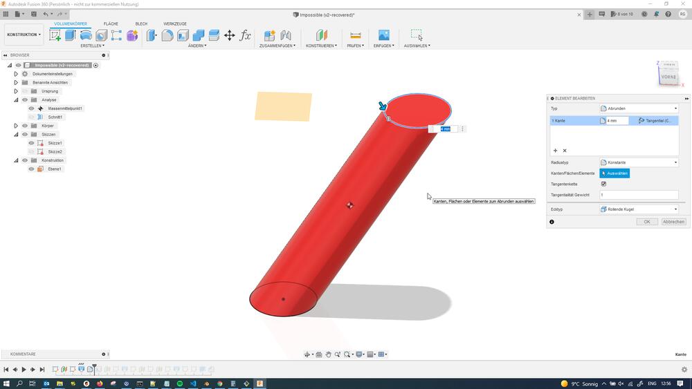
…and rounded off the top edge using a fillet:
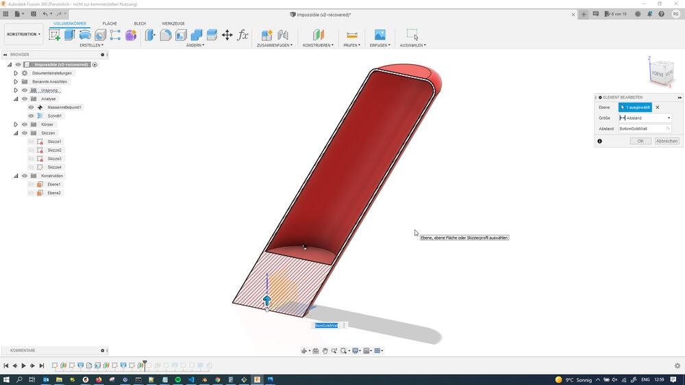
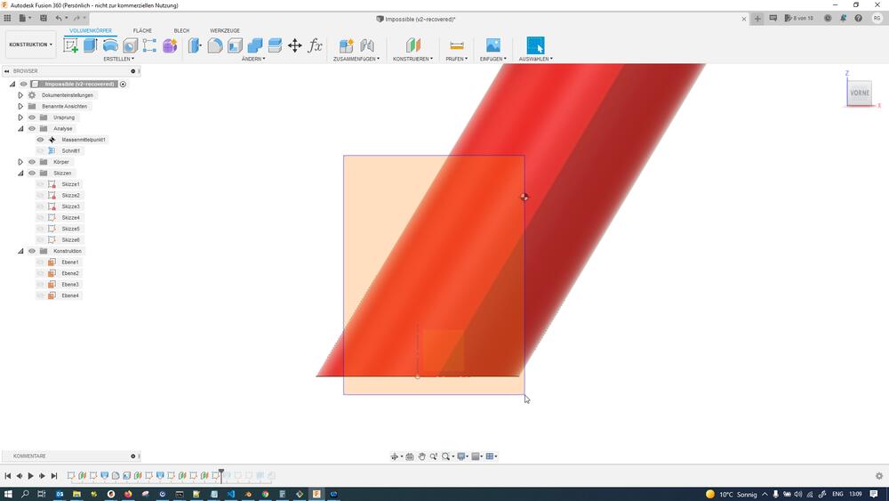
To illustrate the following steps, I added a section view on the XZ-plane:
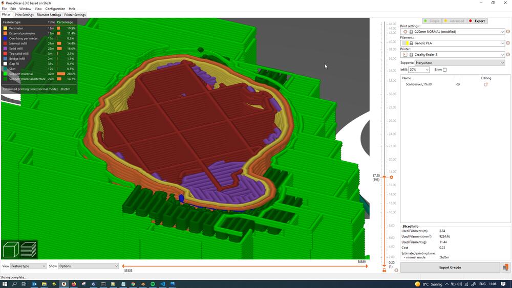
With the section view enabled, I used the shelling operation on the bottom face of the object to hollow it out:
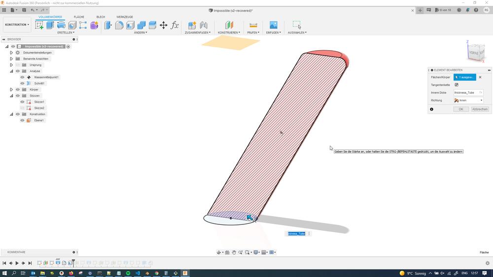
I then created a helper plane at the height where I wanted my massive infill to end vertically…
…and created a sketch on it that intersected the 3D geometry already there, leaving me with a circle the shape of the object at the top height of the internal, massive infill:
I then created a loft between the base footprint circle and the top-of-the-infill circle to fill out the bottom of the object shell again:
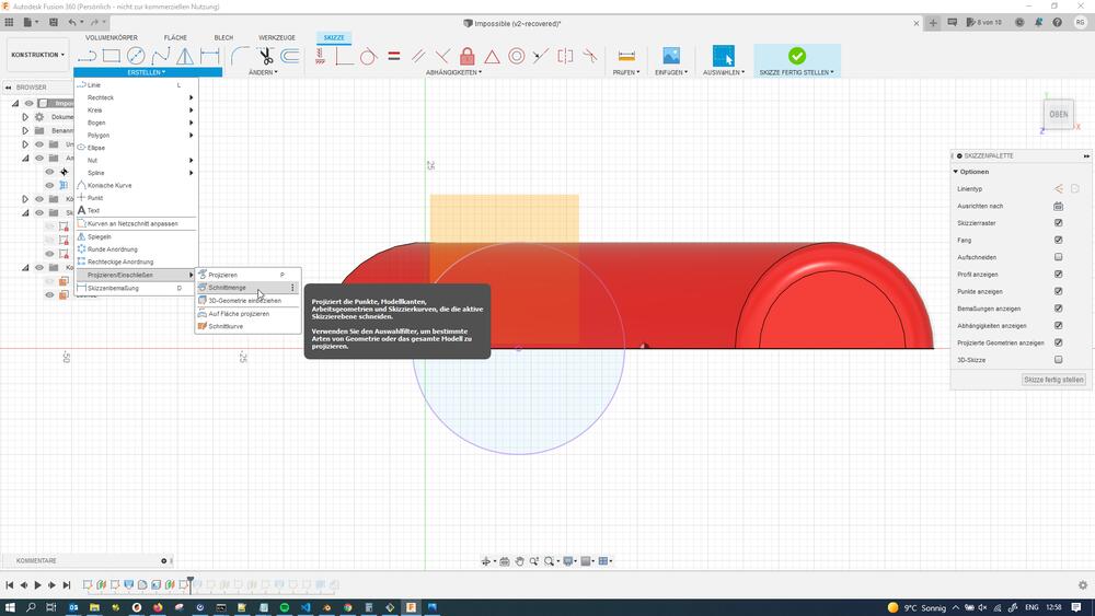
I next created a starting plane for the coin void…
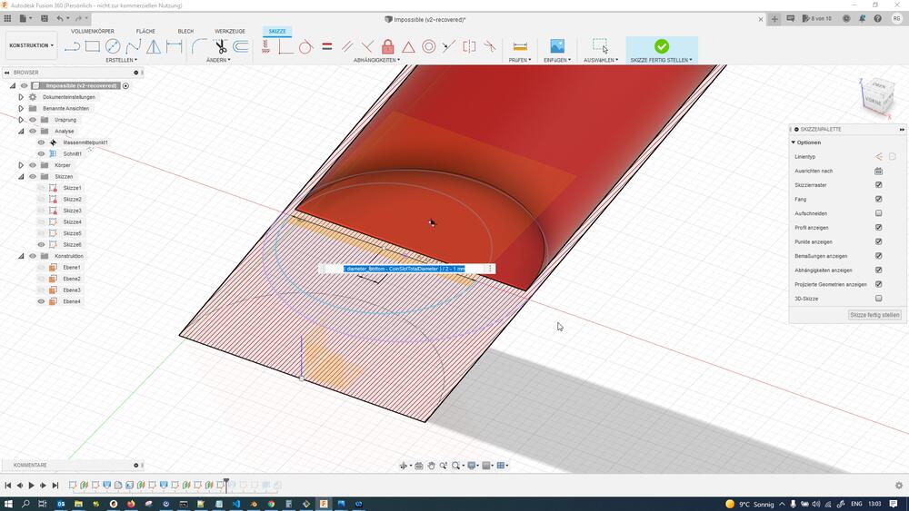
…and sketched the base of the coin void - essentially using the diameter of the coins to be used (5 cent Euro-coins) with an added radial clearance for easier insertion:
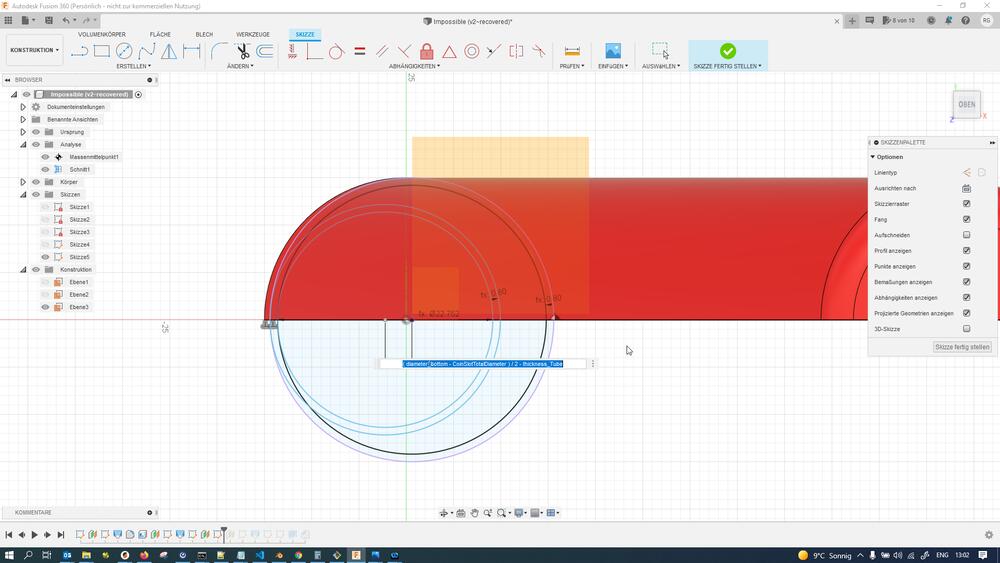
I then created a helper plane at the target height of the coin void…
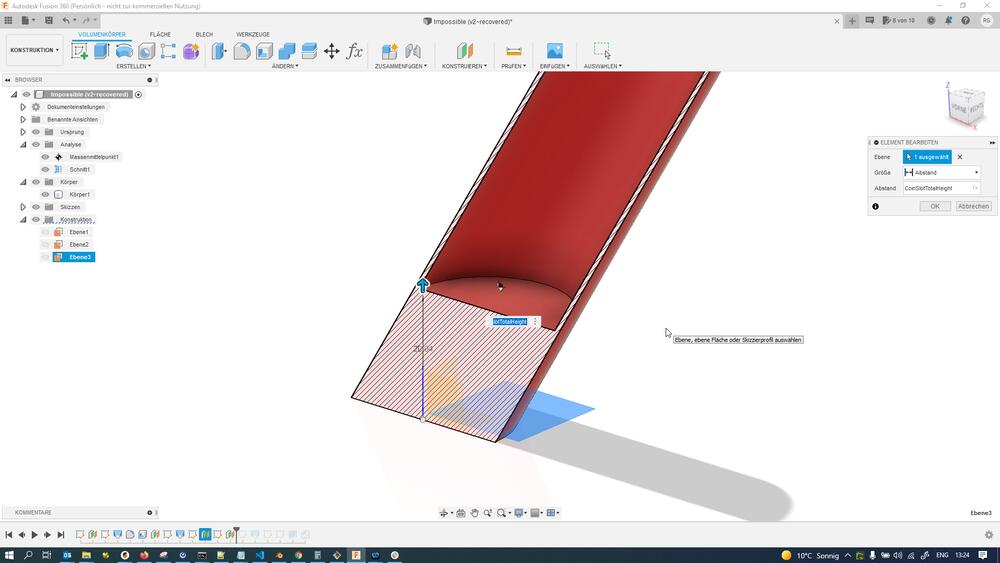
And replicated the coin void base sketch up there:
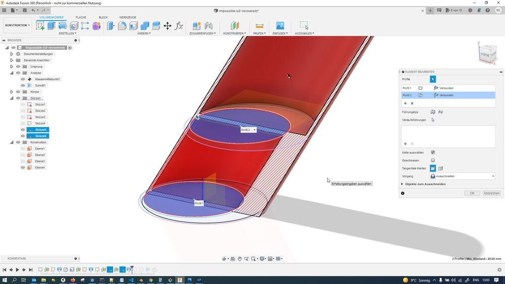
I then created a loft feature between the coin void base and target sketches, which I made subtractive to cut away from the massive base of the object:
To help the object stand up, I decided to fill in the volume right above the footprint again. To do so, I created a sketch on the top-of-the-massive-infill plane and projected the objects footprint onto it…
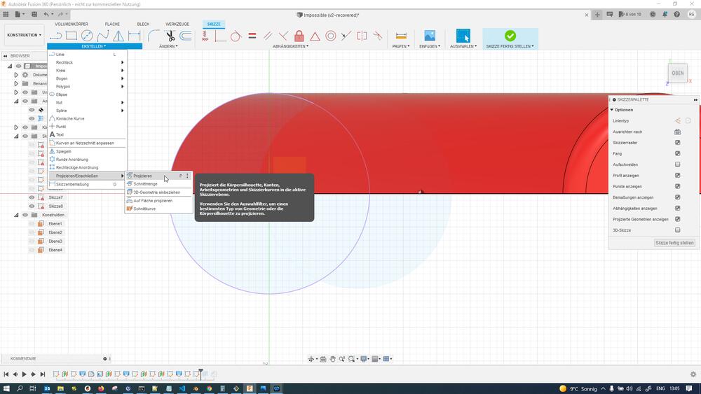
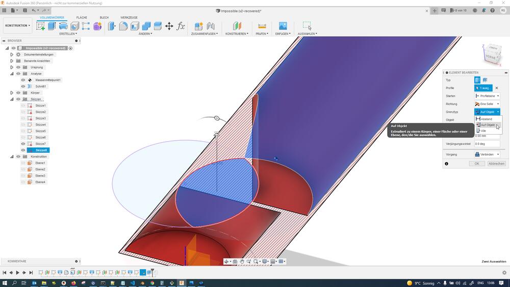
…and then extruded the resulting crescent shape upwards, making sure to select “To…” where the feature asks for its extent and selecting the internal, rounded wall of the cylindrical shell as a target. The resulting extrusion looks as follows:
Finally, I added a little chamfer to the base of the object to make printing easier and remove sharp edges:
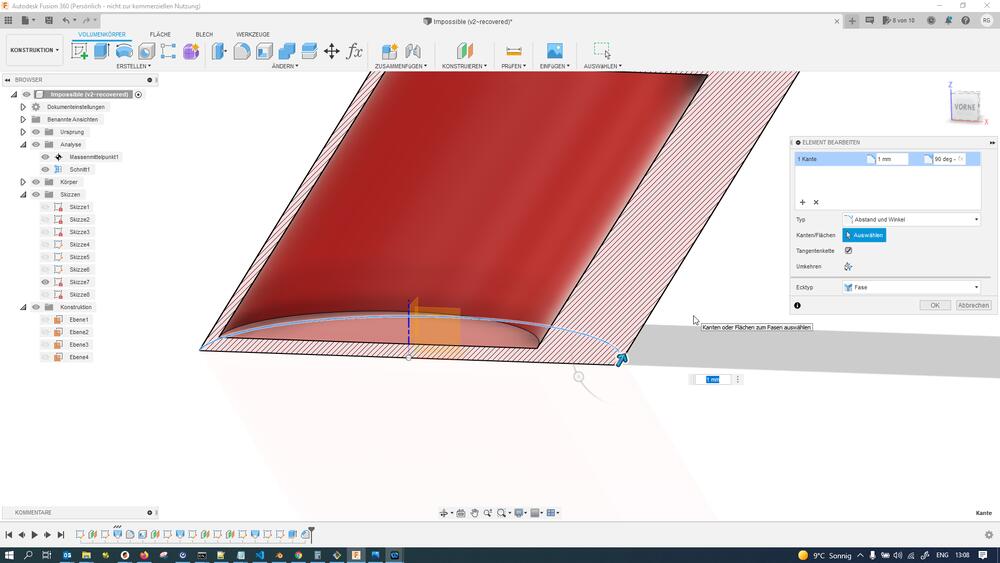
Here is an estimation of the CoG in relation to the footprint of the object. Here it looks like the CoG is outside the footprint, but this was after removing the internal void that would later be filled with (much-heavier-than-PLA) metal coins. The CoG should easily shift inside the footprint later with the coins added.
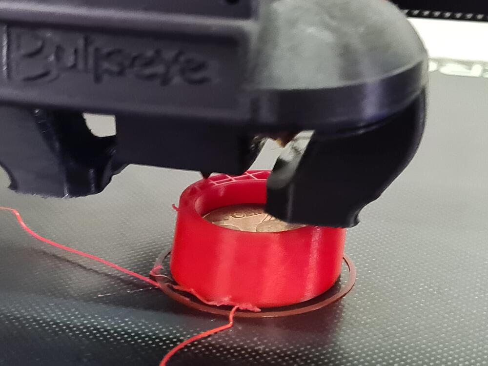
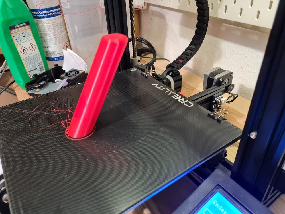
I then went ahead and printed the object on the Ender 3, pausing the print at multiple heights to insert coins while printing (11 coins for a total weight of 43.12 g):
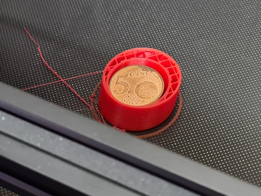
The print continued with the ballast inserted just fine - a common practice to make objects heavier without any visible gaps:
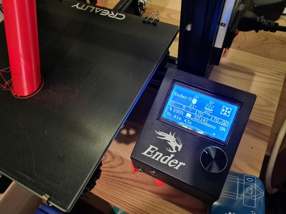
The finished print with internal ballast…
…and the print statistics afterwards:
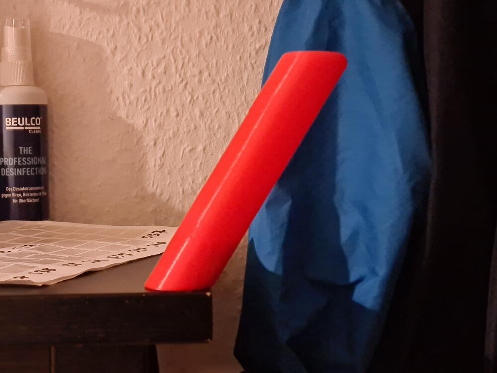
The finished print standing on the edge of a shelve…
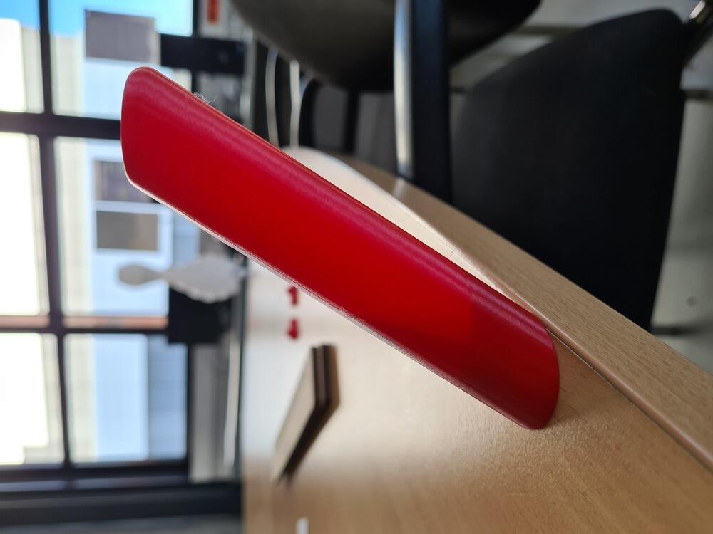
…and a table, making the internal ballast and infill visible against the light:
Design Files
- 3D scan file (BLEND, Blender & STL, Generic):
- High resolution scan files not available due to copyright concerns, highly decimated versions see below!
- Beaver_0.1percent_forPublication.blend
- Beaver_0.1percent_forPublication.stl
- Impossible Object model file (F3D, Fusion360):
- Impossible Object mesh file (STL, Generic) (for 3D-printing, must stop print manually at proper heights to insert weights!):