14b. Group Assignment
This is the group assignment webpage for Kamp-Lintfort FabLab’s Kleve branch group assignment, week 14, Input Devices. Until hosted on the FabLab KaLi (or FabLab.blue) site, it can live here.
Reading Digital and Analog Signals
For this week’s group assignment, we were tasked to look at the outputs produced by a digital as well as an analog sensor. We chose a joystick module for our assignment, as it contains both analog sensor components:
- The x- and y-angle of the joystick are measured using two perpendicular potentiometers on the joystick module, which give analog signals (the voltage at the potentiometer wiper).
- There is a momentary pushbutton that registers clicking the joystick. This is a digital input, as it simply closes a circuit. The button connects the button pin to GND when pressed.
Measurement Equipment
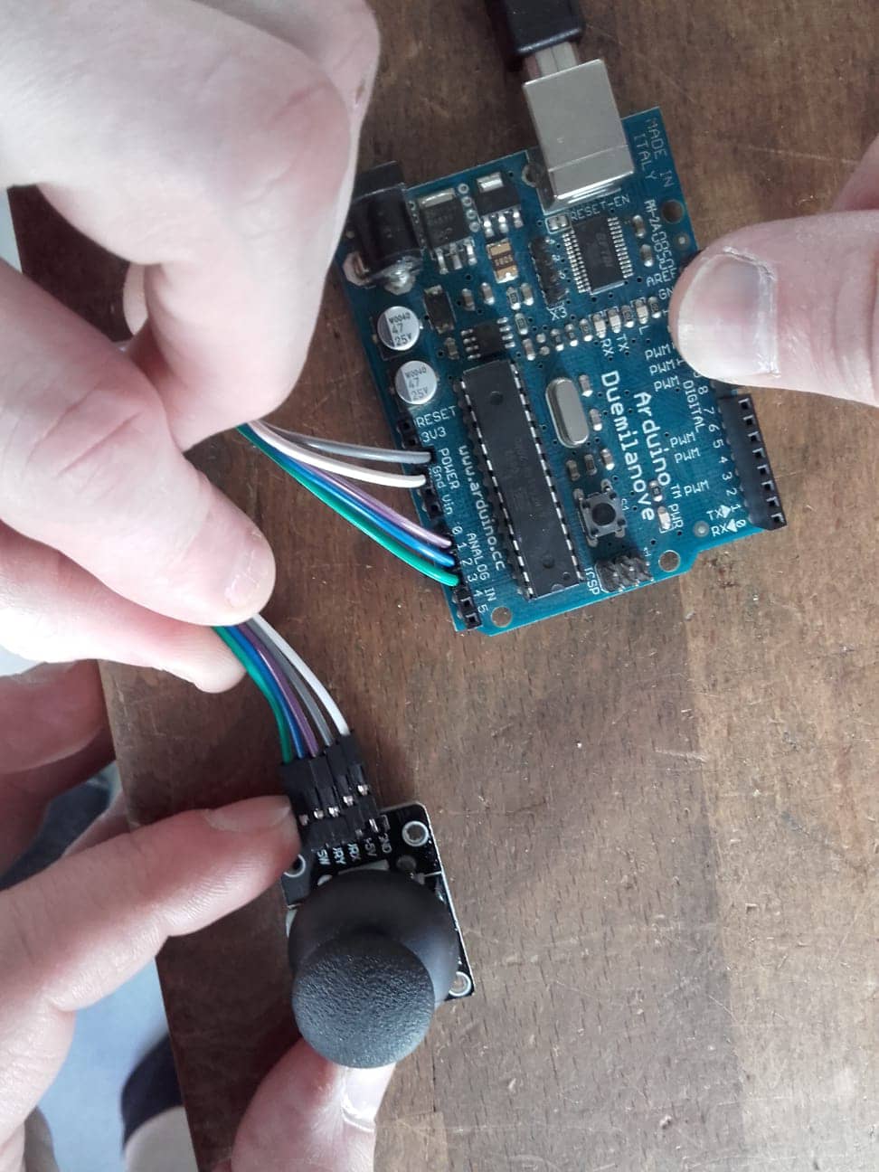
Here’s the circuit with the joystick module connected to the Arduino using jumper wires. We used pins A0 and A1 for connecting the x- and y-wipers of the joystick and connected the switch to pin A2:
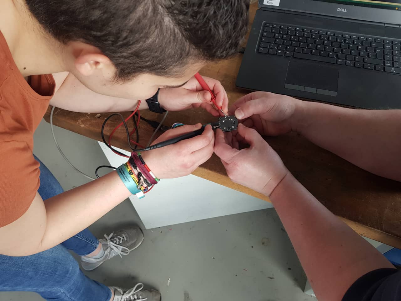
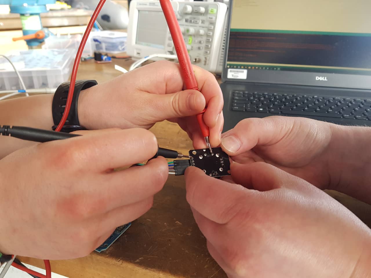
Since we didn’t design the joystick module, we first had to find out what the button connected to. Here’s Leen and Roland finding out (using a multimeter) that the button connects the button pin to GND when pressed:
Programming
We used an Arduino to read both the analog and digital signals at the same time. We started out by just reading the analog channels and sending the values read to the serial port - the output can be seen here on the Serial Monitor:
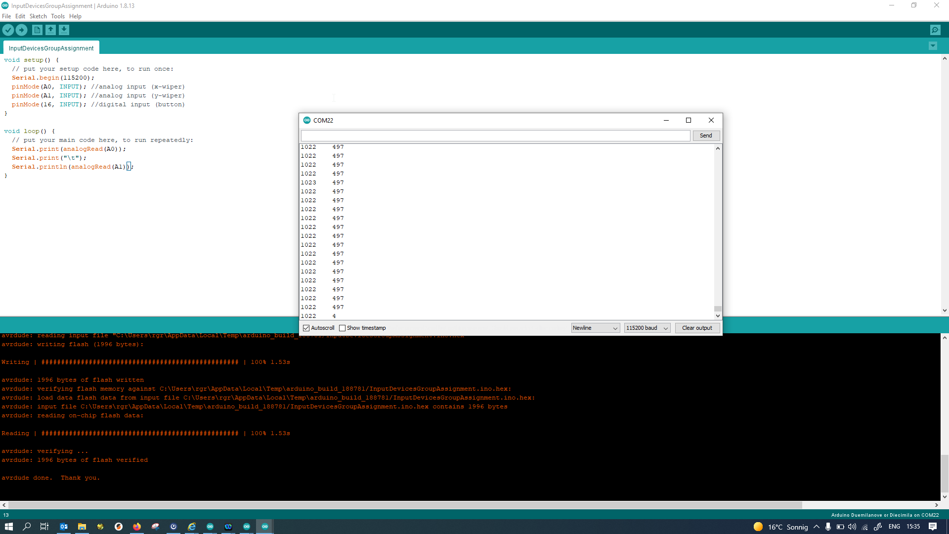
The "\t" in the Serial printout creates a tabulator character, aligning columns of values nicely when they are not too long. Finally, we also added the joystick module’s button (when pressing down on the joystick) as a digital sensor and added its readout to the Serial output:
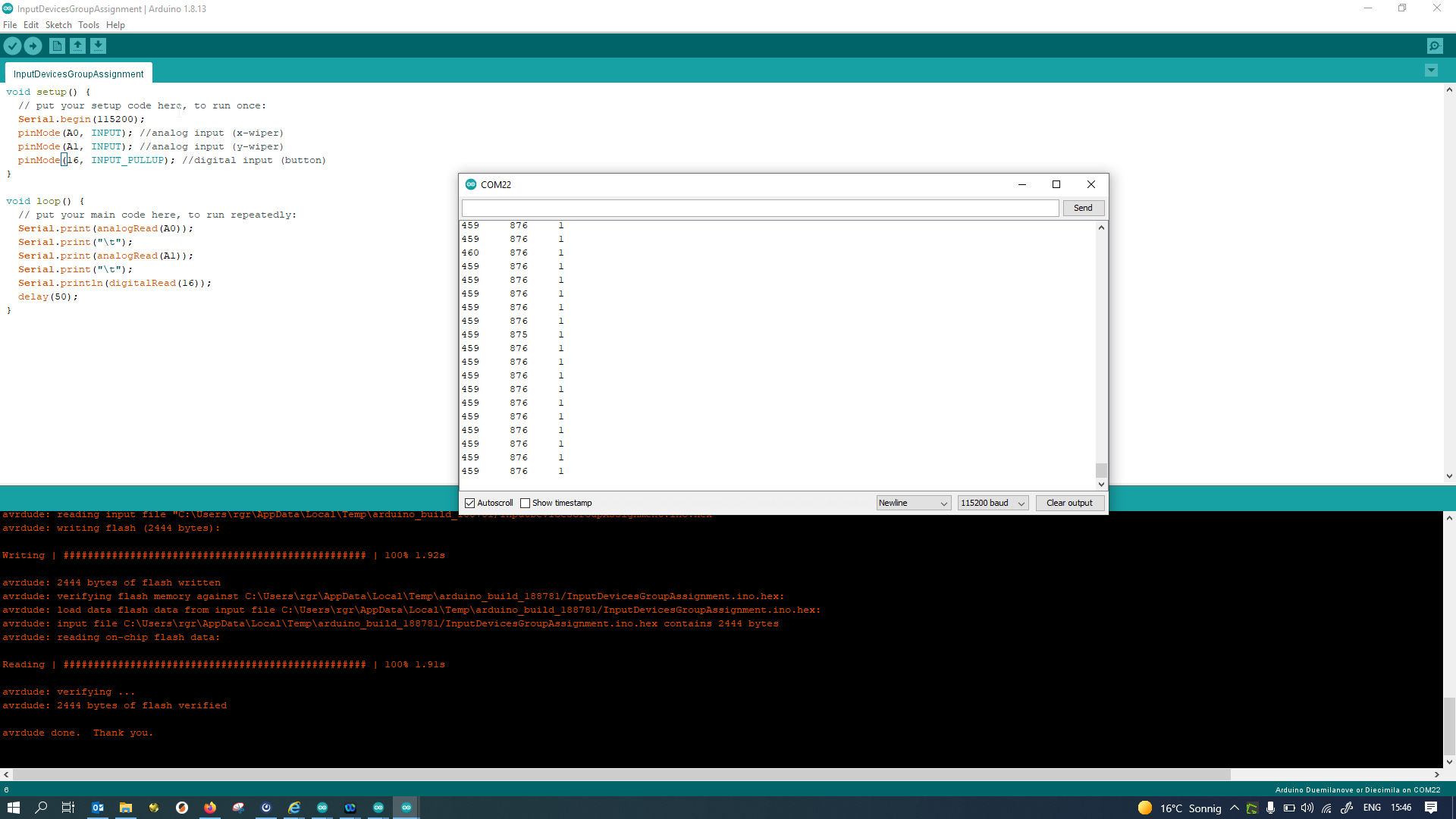
Here is the same code as a text snippet:
//Code for reading the x-, y- and button inputs from a joystick sensor module.

void setup() {
  Serial.begin(115200);
  pinMode(A0, INPUT); //analog input (x-wiper)
  pinMode(A1, INPUT); //analog input (y-wiper)
  pinMode(16, INPUT_PULLUP); //digital input (button)
}

void loop() {
  Serial.print(analogRead(A0));
  Serial.print("\t");
  Serial.print(analogRead(A1));
  Serial.print("\t");
  Serial.println(digitalRead(16));
  delay(50);
}
First, in the code the three input pins are set up as input pins. There are two analog inputs A0 and A1, but since we were using the third input A2 for digital input, we called it by its digital pin name, 16, instead of A2, just to be explicit about it being a digital input. It would have worked the same if called A2 in code.
Since the pushbutton connects the button pin to GND when pressed, we want to use a pullup resistor on the input pin to pull it high when not pressed (hence the INPUT_PULLUP part in the pinMode declaration). In the end, this code allowed us to read all analog and digital sensors provided by the joystick board.