4b. Group Assignment
This is the group assignment webpage for Kamp-Lintfort FabLab’s Kleve branch group assignment. Until hosted on the FabLab KaLi (or FabLab.blue) site, it can live here.
The Fabulaser Mini
The Fabulaser Mini is a laser cutter developed for FabLabs by FabAcademy alumnus Daniele Ingrassia. It sports a 40 W CO2 laser tube to cut materials up to about 10 mm (acrylic) on a cutting area of 60 x 40 cm. The bed for stock to rest on is made out of L-shaped aluminum profiles and sits on a sturdy frame made of aluminum machine construction profiles. The whole cutting bed can be manually raised or lowered by screwing the 4 feet inwards or out. It has a clear lid, internal LED lighting and an exhaust port in the back of the cutting chamber. In the back of the machine, there are connectors for an air exhaust hose, an air inlet for compressed air to be sent to the cutting head and an in- and outlet for water for cooling the laser tube.
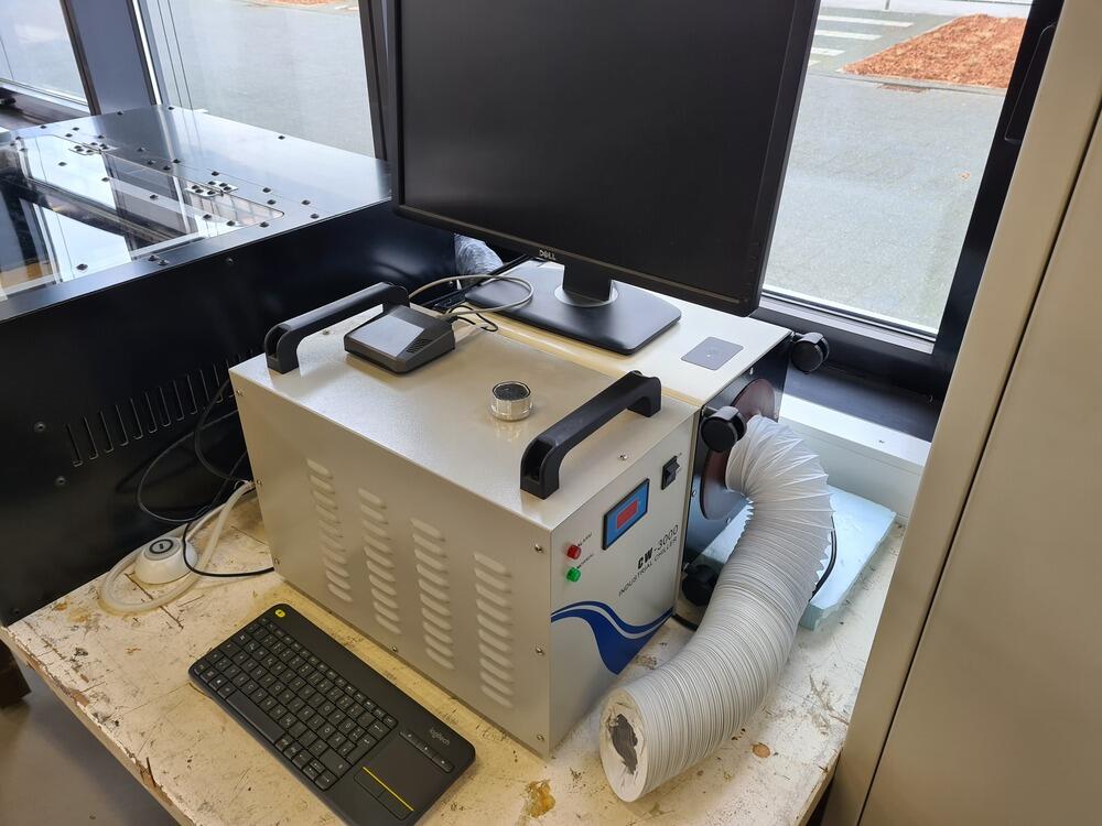
Here’s an overview over our laser workspace right now:
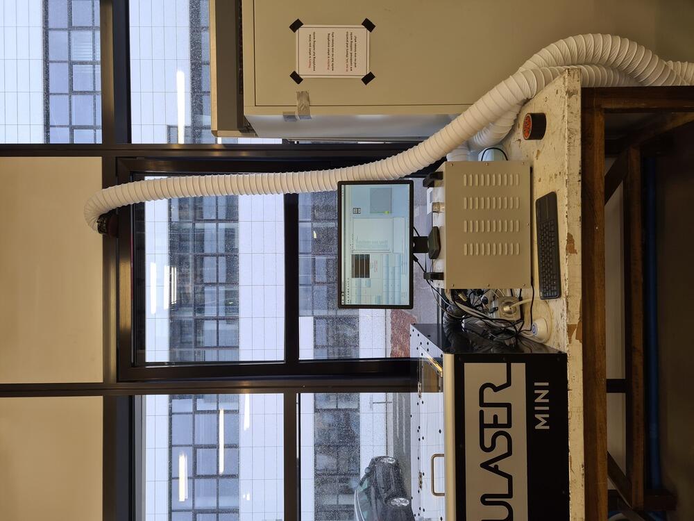
The laser cutter needs a few extra machines to work properly. An industrial water chiller is used to cool down and circulate the water for cooling the laser tube. This is connected to the water in- and outlets at the back of the laser. A small air compressor is used to provide unlubricated, compressed air and is connected to the air inlet of the machine. An air exhaust filter (retrofitted with both in- and outlet for air exhaust hoses) is used to extract and filter the polluted air produced when cutting. This is attached to the air exhaust on the back of the machine, the other side of the filter exhaust is hung out of a cracked window to vent the filtered air outside.
Here’s an overview over our laser workspace (back left: laser, front left: chiller, front right: filter, on chiller: Raspberry Pi 4 4Gb):
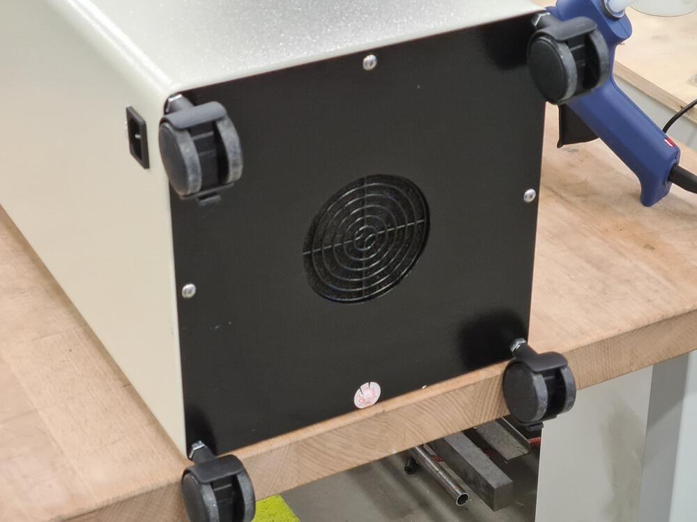
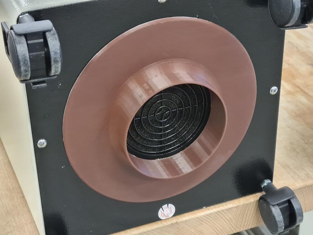
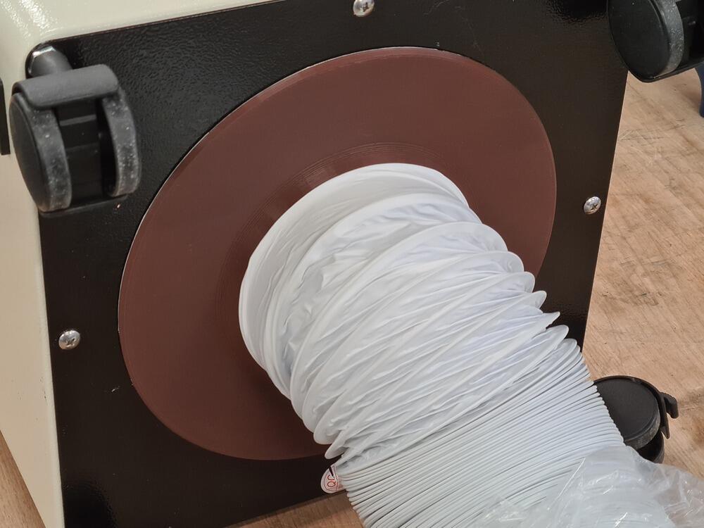
The filter used to have no targeted exhaust and simply blew the filtered air (which was still smellable) downwards onto the table. To really get working with the machine, we glued on an exhaust hose adapter and operate the filter lying on its side now (as the wheels don’t have enough ground clearance for the hose):
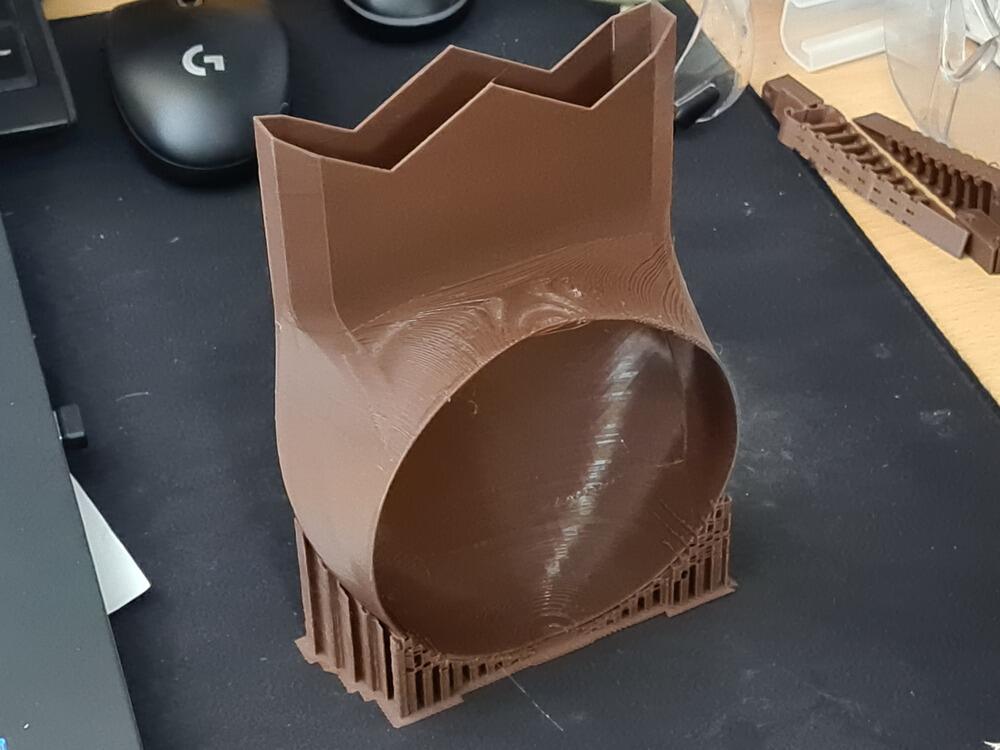
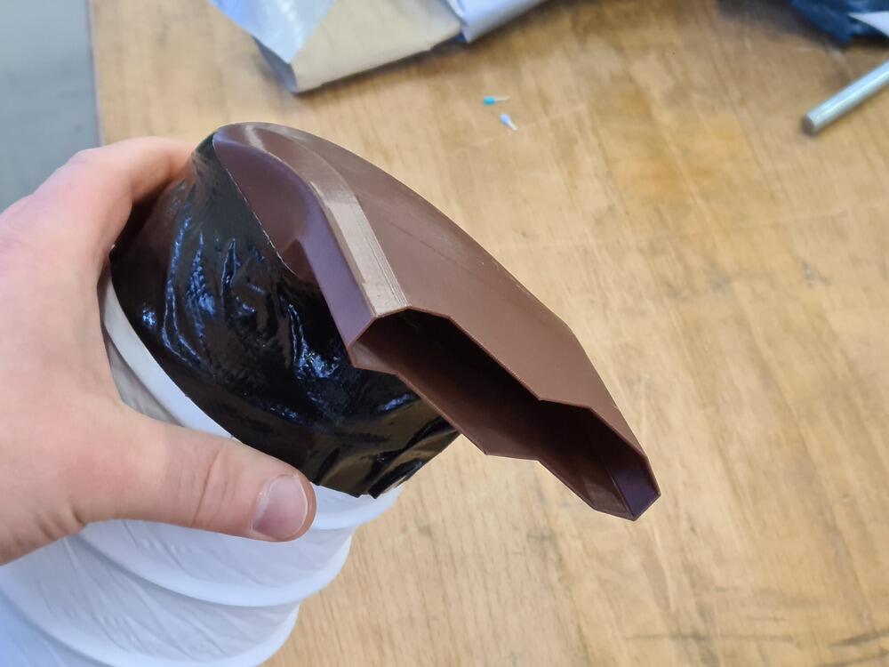
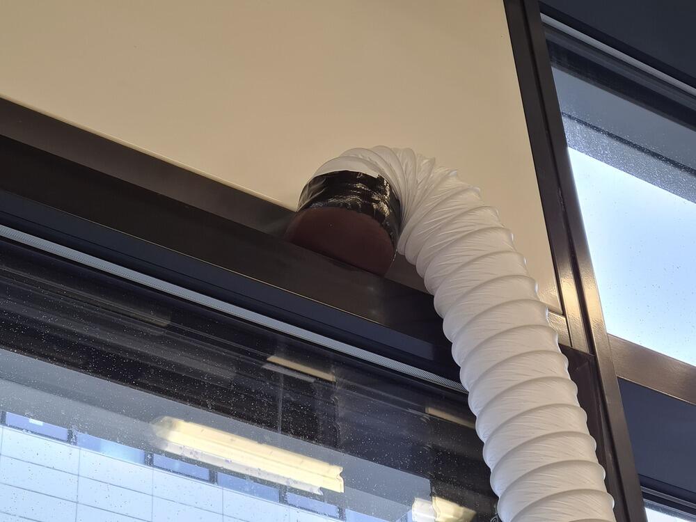
To feed the other end of the exhaust hose through the cracked window (which - due to exceedingly deep window frames - only left a crack of around 2.5 cm all around to work with), we printed another adapter to change the profile from round to rectangular:
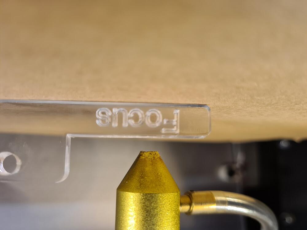
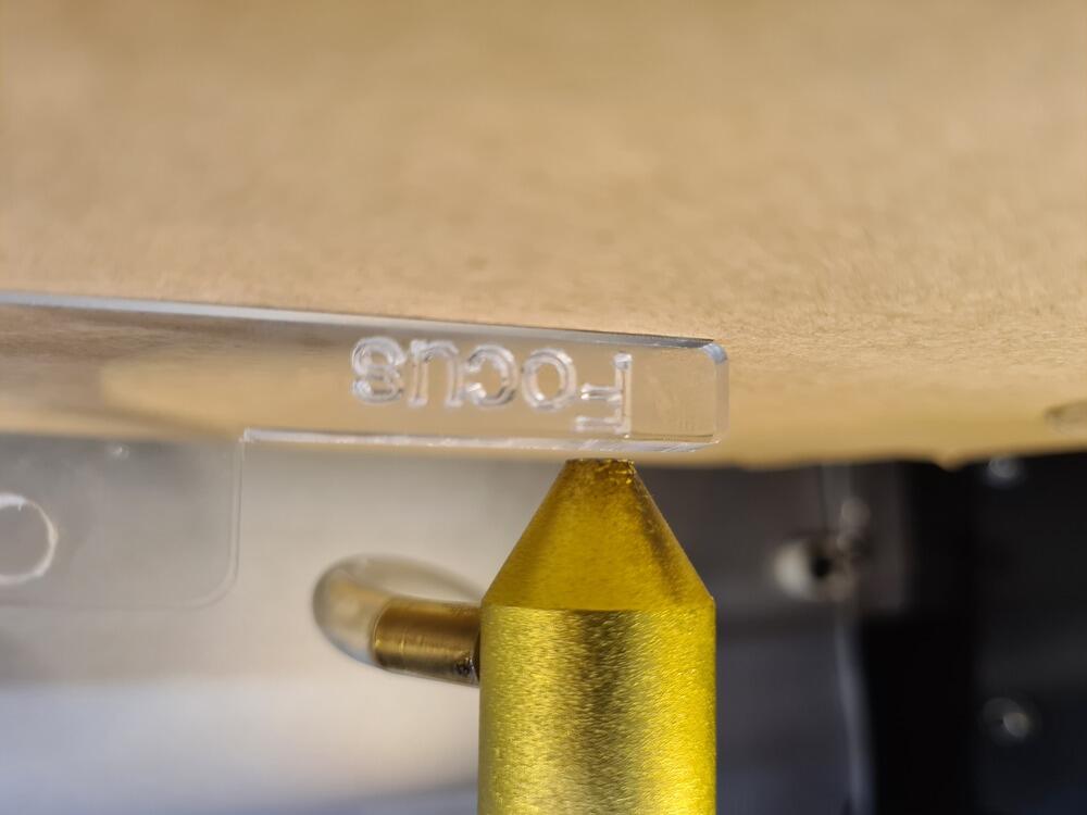
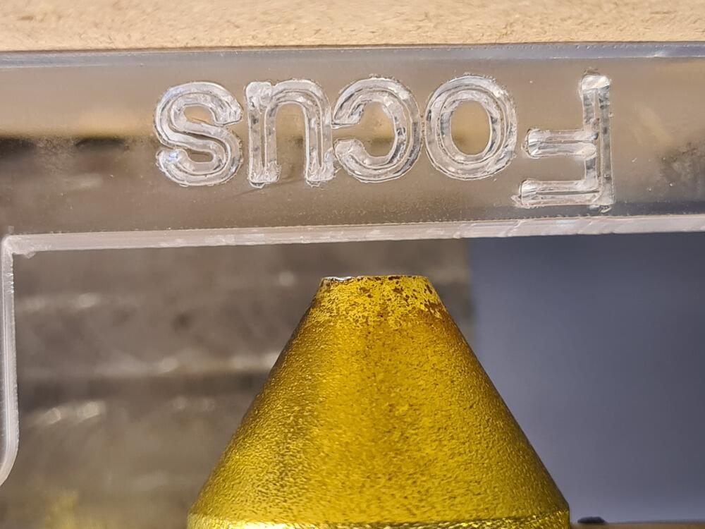
The cutting head uses a lens of unknown focal length - there is a template distance piece for setting up the focus though. From personal conversation, we were assured that the focused part of the laser beam would be long enough to not have to be too precise when setting it up - it should still cut just fine. A long focus like that does indicate that the focal length is probably relatively large, causing the beam to focus into a relatively narrow cone. The focus of the laser can be hanged to a certain extent by screwing and unscrewing the lens assembly, effectively lowering or raising the lens - this is very, very limited though and there is not a large range to play with. In fact, for thin materials, the focus cannot be set up perfectly without raising or lowering the whole bed (which is a slightly more involved operation…).
Focus on the machine is set up manually using a distance piece (if the nozzle touches the distance piece, the top surface of the material is in focus). On the following two pictures, the second picture shows the closest focus possible on a 1.5 mm thick cardboard piece - not quite there. One can also see the air assist port sticking out in different directions.
The proposed Fabulaser Mini toolchain consists of Visicut (a Gcode generator from RWTH Aachen) to generate Gcode files from vector designs and Universal Gcode Sender Platform (UGS Platform) to stream the Gcode from a host PC to the laser cutter mainboard. The connection between laser cutter and host PC is a standard USB-A connection (using a USB-B to USB-A cable commonly found in printers, scanners etc.). There is a configuration file for Visicut containing all the necessary information for the Gcode to be created properly. The maximum speed of the laser cutter is (by the Visicut config file) 24000 mm/min, so 24 m/min or 0.4 m/sec. The maximum speed in Visicut is used for setting up cut speeds in relation, so when a cutting speed of 2 was chosen in Visicut, this would equate to 2% of 0.4 m/sec, ergo 0.8 cm/sec. The rate - as far as we know, can not be set up in this toolchain (or even on the hardware side itself).
Cutting/Marking Parameters
For test cuts, we generally employed the following algorithm:
- Focus the laser manually at the top of the material (we don’t have a controlled way of stepping the focus down from there, so for consistency’s sake we kept it at the top for now)
- Start out at a power of 100%, speed 5% (~2 cm/sec)
- If material cuts already, lower power until not cutting all the way through anymore, keep the lowest power as a setting then (speed 5 produces good enough geometry even on small texts and such)
- If material doesn’t cut yet, lower speed until material cuts at 100% power, keep this as the cut settings.
For test markings, we used the following:
- Focus the laser manually at the top of the material (reasons see above, in this case the top would actually be what you want to focus at anyways)
- Start out at a power of 7.5%, speed 5% (~2 cm/sec)
- If material marks already, check whether darkness of marking is satisfactory
- If material doesn’t mark yet (or not dark enough), increase power slightly or decrease speed slightly (in 1% increments)
We ended up with the following laser parameters:
| Operation | Material | Power | Speed |
|---|---|---|---|
| Cutting | Cardboard, corrugated, 1.5 mm | 50% | 5% |
| Plywood, 3-ply, 5.72 mm | 100% | 2% | |
| Marking | Cardboard, corrugated, 1.5 mm | 8.5% | 5% |
| Plywood, 3-ply, 5.72 mm | 10% | 2.5% |
Kerfs
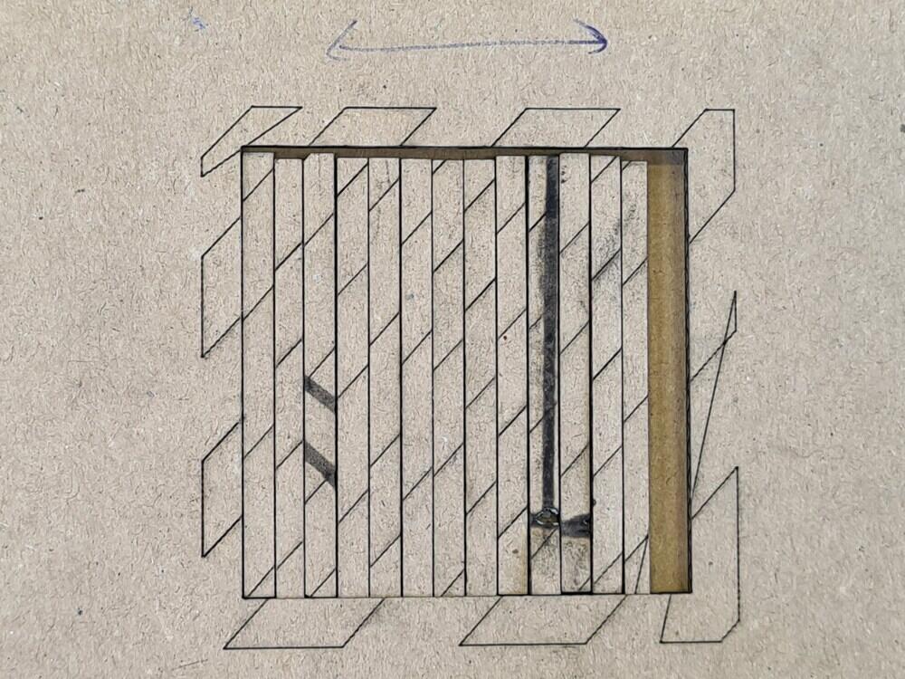
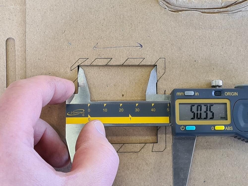
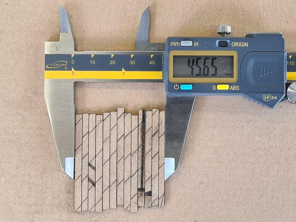
Using aformentined cutting parameters, we did test cuts and calculated the kerf. For doing so, an Inkscape SVG file was prepared that would cut 13 bars of a certain width (so doing a total of 14 cuts). The exact width was not important, as the total width of the remaining bars would later be measured. After Cutting the 13 bars out of the stock material, the inside dimension A of the hole was measured using digital calipers. The bars were then laterally pushed together and the total width B over all 13 bars was measured. The difference C is the total gap left behind by the comined kerf of all 14 cuts, thus C = A - B. Dividing C by the number of cuts yields the width K of a single kerf: K = ( A - B ) / 14.
Cutting the bars:
Measuring A (inside measurement):
Measuring B (total outside measurement):
Caveat: Bad focus for thin materials, can’t got any further than that (which should widen the kerf):
For the two materials measured, we arrived at following results:
| Material | Kerf | Notes |
|---|---|---|
| Cardboard, corrugated, 1.5 mm | 0.34 mm | Focus not perfect (~1 mm above top surface) |
| Plywood, 3-ply, 5.72 mm | 0.21 mm | Focus on top of material |
Clearance Tests
We did run clearance tests for multiple materials this week. Since none of us was working with acrylic, we limited ourselves to cardboard and plywood for now. The results of our tests can be found below.
Corrugated Cardboard, 1.5 mm
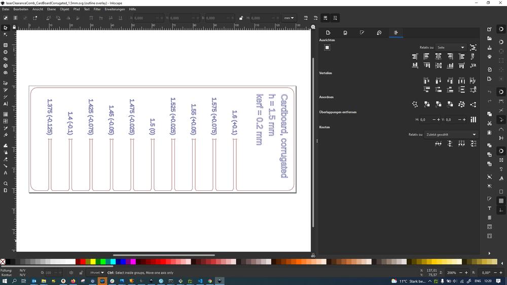
First, we used the clearance comb generator to prepare the cut files for the clearance comb. We exported an SVG file from OpenSCAD, then opened it in Inkscape, broke apart the path, gave all of the shapes a hairline contour, no fill and changed the outline color to red, the text outline color to blue (red lines would be cut later blue lines would be marked):
We then went ahead and prepared the Gcode for the laser using Visicut, cutting at power 50, speed 5 and marking at power 8.5, speed 5. Here’s shots of the laser just finishing up the last cuts and the finished comb (one can see it drop from the bulk material as it’s completely loose):
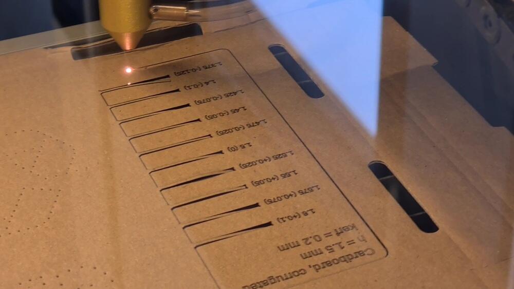
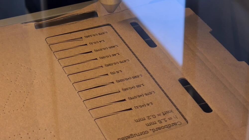
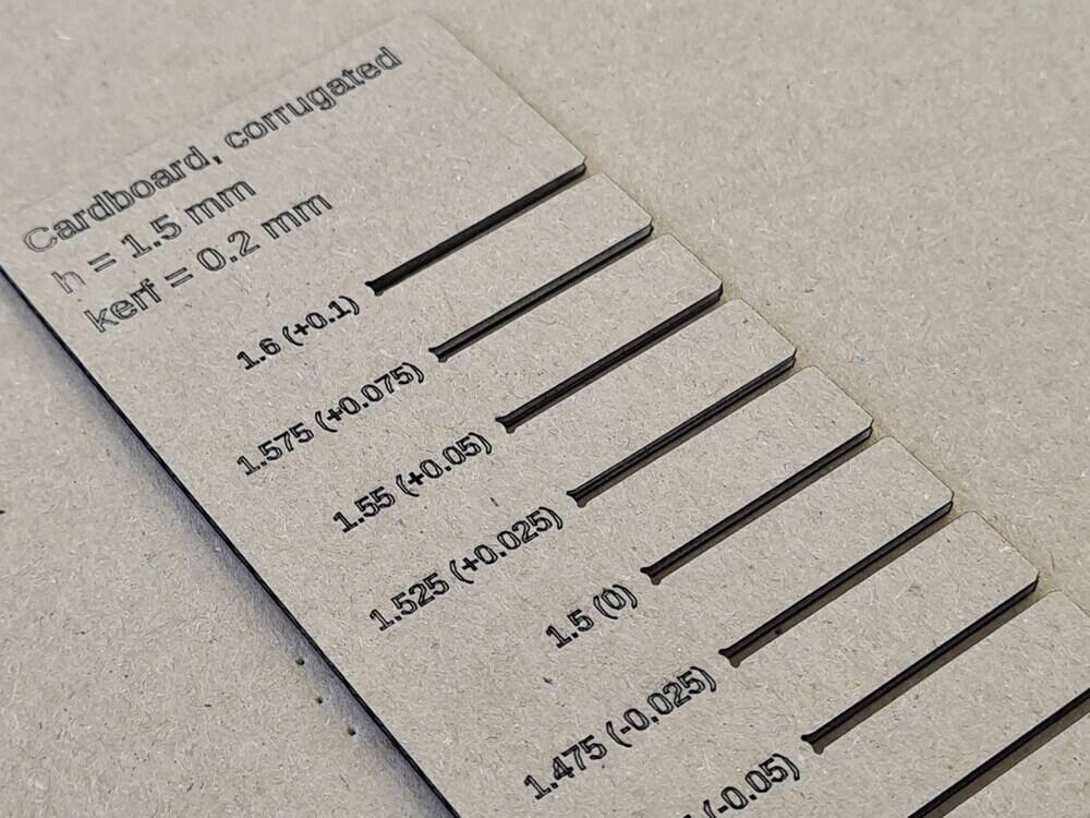
The thin, corrugated cardboard cut very nicely and produced clean edges. In the following shot you can see all the features of the comb (incremental slots with labels, label field, circular cutouts at slot base, chamfer (60° here) at the slot top):
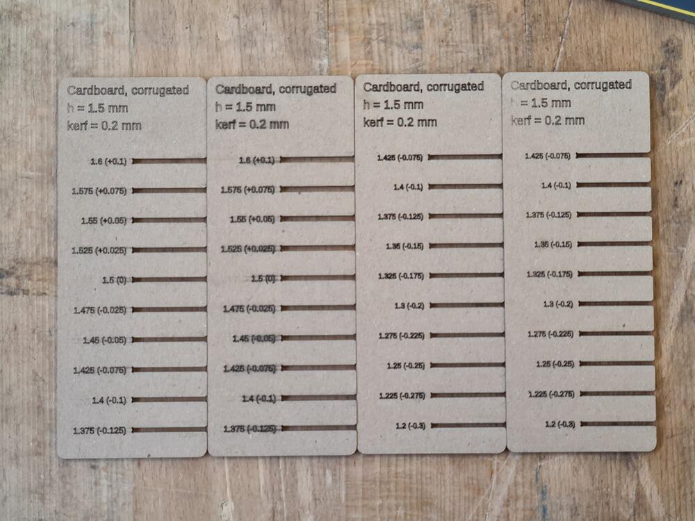
As we found even the thinnest slot with the chosen increments to be rather on the loose side, we prepared another set of combs that started at a lower negative end of the range (but at same increments). We found out that 1.3 for slot width (as designed) would make for a good, solid friction fit:
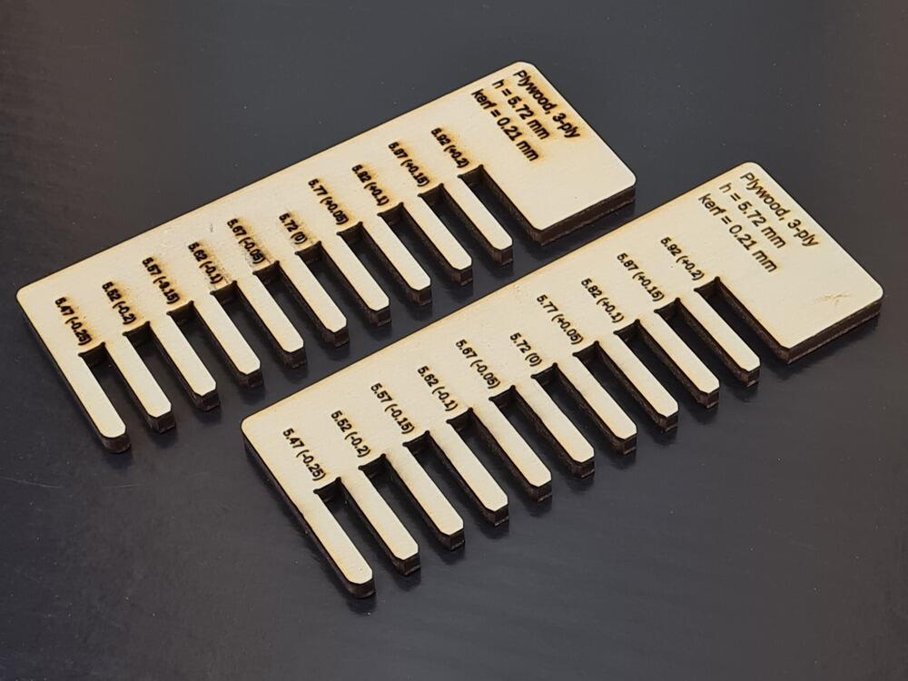
Plywood, 3-ply, 5.72 mm
We repeated the same steps as above for plywood, using the clearance comb generator to prepare a clearance comb. We also used another comb design by Aaron, which yielded similar results. For this plywood, we found an interference of 0.2 mm (so a slot of 5.52 mm width) to give the strongest friction fit.
Important learnings about our machine
- Setting up the focus is not really fun and doesn’t work too precisely. When turning the thread of the lens assembly to raise or lower the lens, certain points (where focus might be optimal) are not feasible to cut with, as the air assist inlet is in such an inconvenient position then that it kinks the air assist tube.
- Generally, the focus range is pretty limited and - at the given table height we have now - really only works well for materials ~3 mm and up.
- Care must be taken not to cover the whole cutting bed when using new, full format stock. If placed over the whole grid, smoke cannot escape well at the back of the cutting bed and collects underneath the stock.
- Care must be taken to remove little bits from the grating underneath the stock, otherwise small remainders of previous jobs can catch fire.
- The machine must not be left unattended - there was no specific situation in our case, but we made sure to repeat that mantra time and again.
- A Raspberry Pi 4 4Gb is strong enough to handle the Gcode streaming, but really lacks when it comes to manipulating vectors (e.g. when preparing cuts in Visicut).
Contributions
- Writeup: Roland
- Images: Aaron, Leen, Roland
- Kerf Measurements: Leen, Roland
- Cut Parameters: Leen
- Clearance Tests:
- Cardboard, corrugated, 1.5 mm: Roland
- Plywood, 3-ply, 5.72 mm: Aaron, Roland