8. Computer controlled machining
Group Work
A detailed documentation of our group assignment work can be found on the shared group assignment webpage.
Background - Computer controlled machining
Since we got our CNC machine in the workshop, I have used it numerous times to prepare and cut jobs with students for making simple structures and fixtures. We exclusively cut woods and plastics on our machine, as we try to keep metal and “soft” machining somewhat separated. From the get go, we used Fusion 360 to prepare the CAM jobs for cutting on the machine, only once did I use pcb2gcode to actually prepare pcb milling Gcode for usage on the big machine. Since I do have some experience with hand building furniture using manual and power tools (electric saws, router, chisels, planes), I do feel familiar with the techniques employed in larger scale construction.
Making a Big Thing
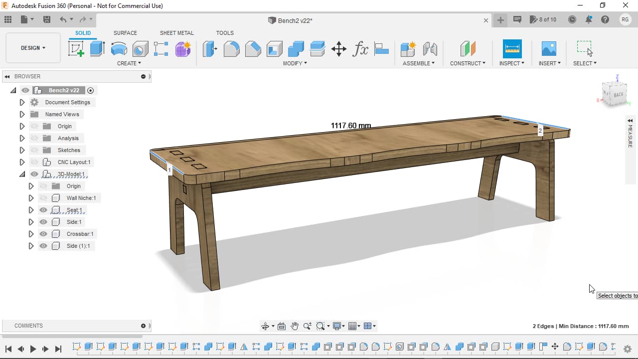
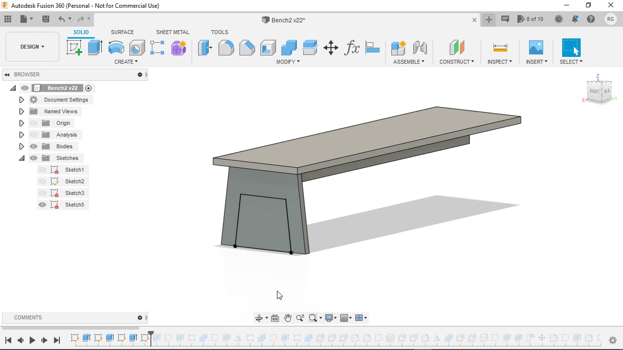
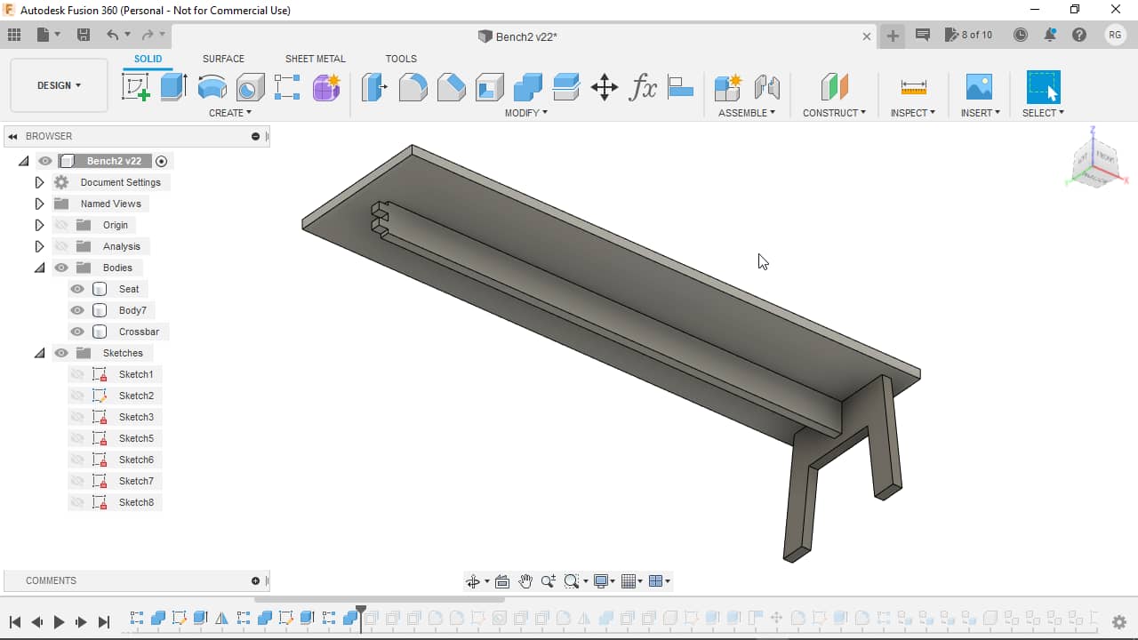
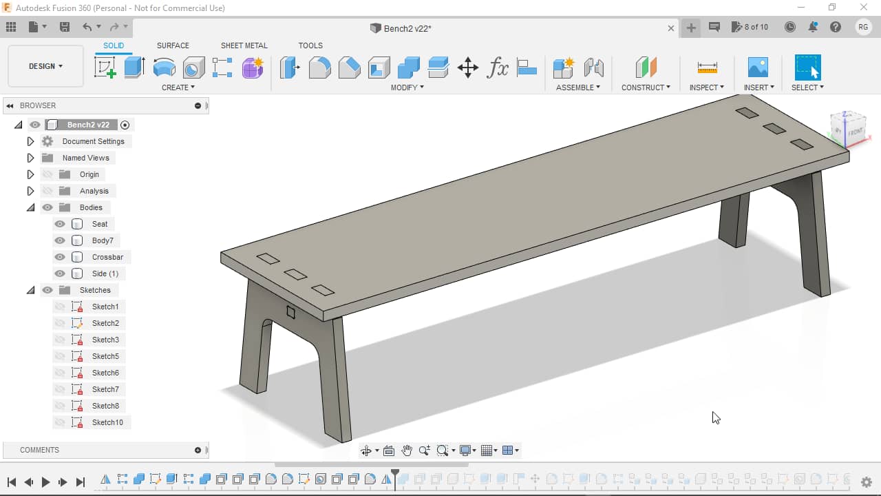
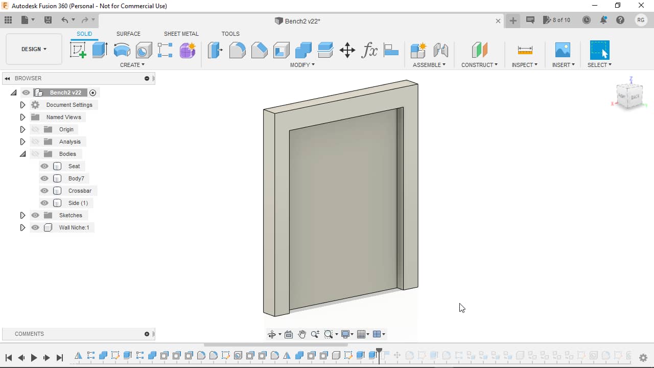
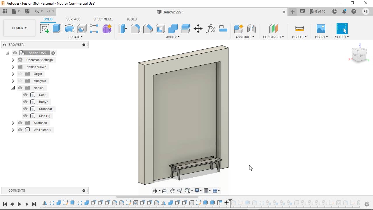
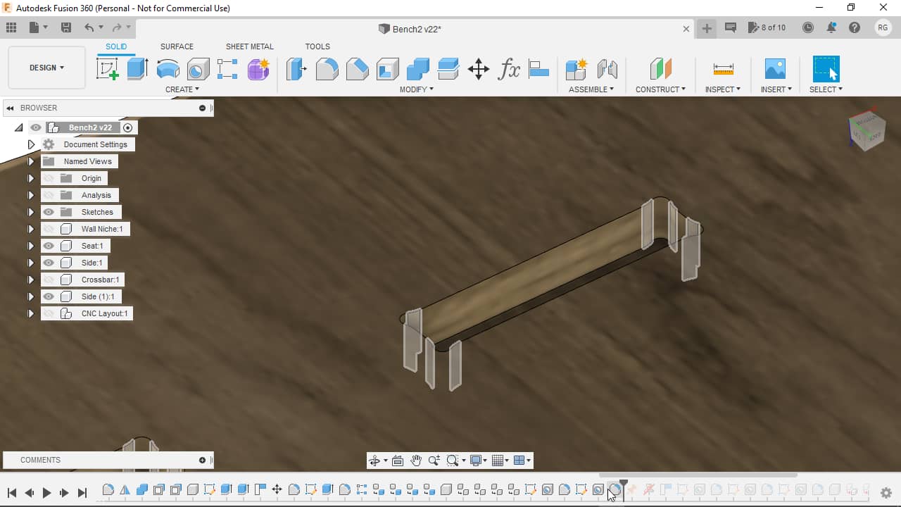
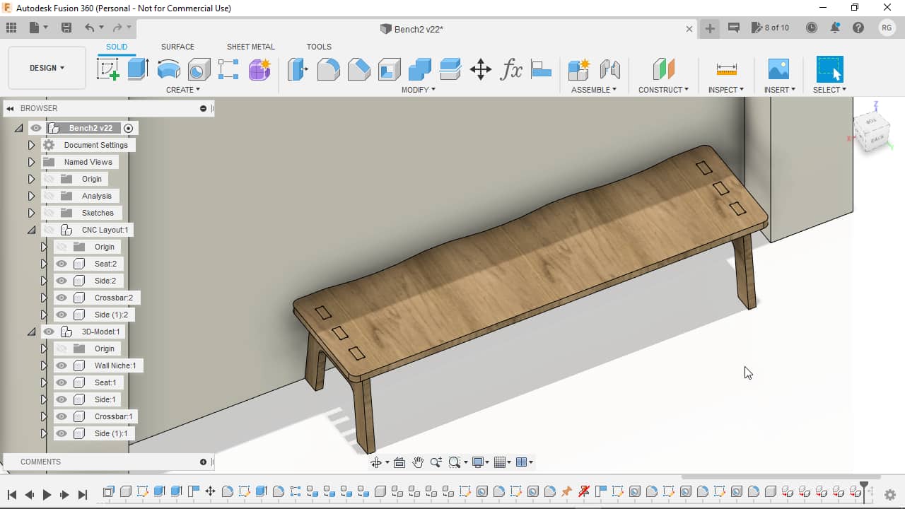
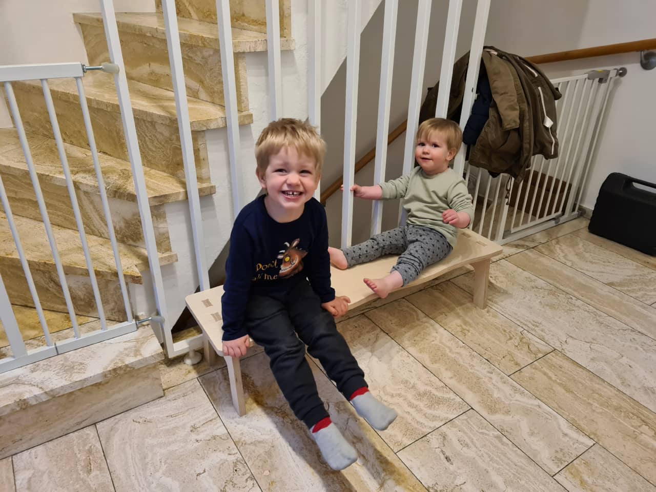
Since we recently moved house, for this week, I decided to make a bench for the entry hallway. During design, I actually slightly changed my mind to make a bench for the kids only, since they like sitting down when putting their shoes on. I designed my bench for three kids sitting next to each other, which left me with a total width of 111.7 centimeters, which puts it in the meter-scale-range.
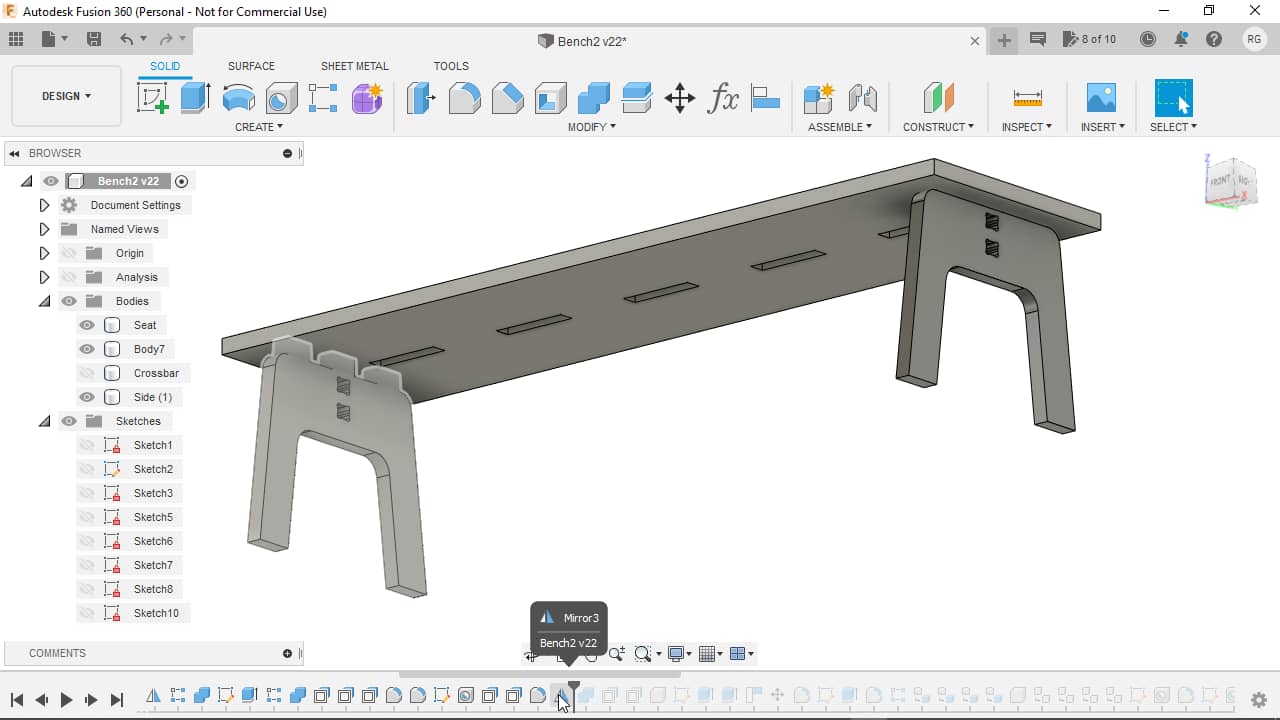
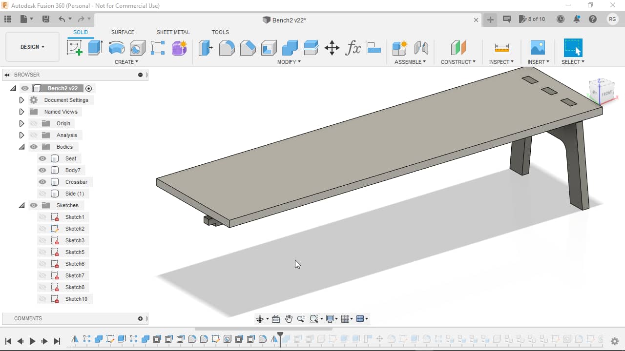
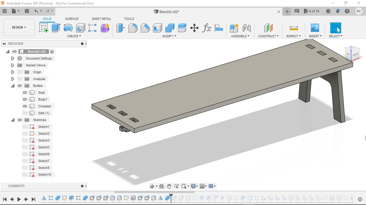
Here’s an overview of the bench I designed with the length measurement…
…and without:

Basic Shapes
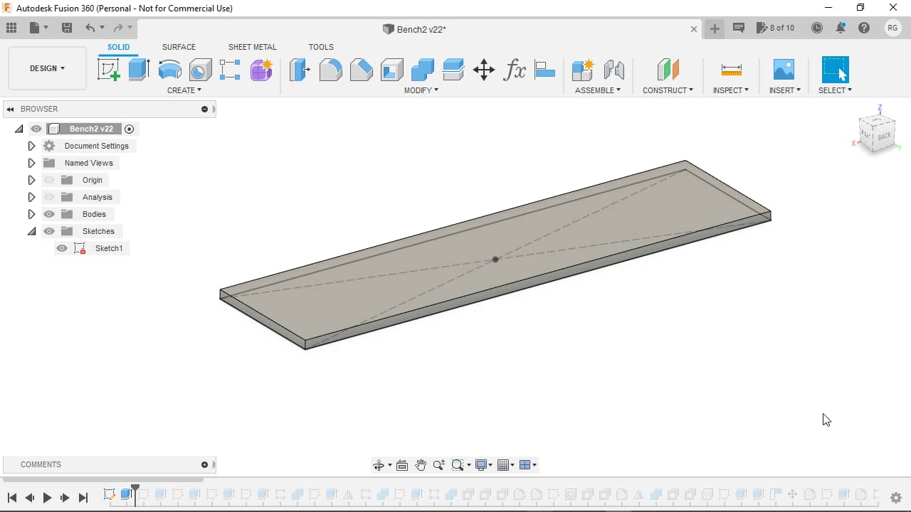
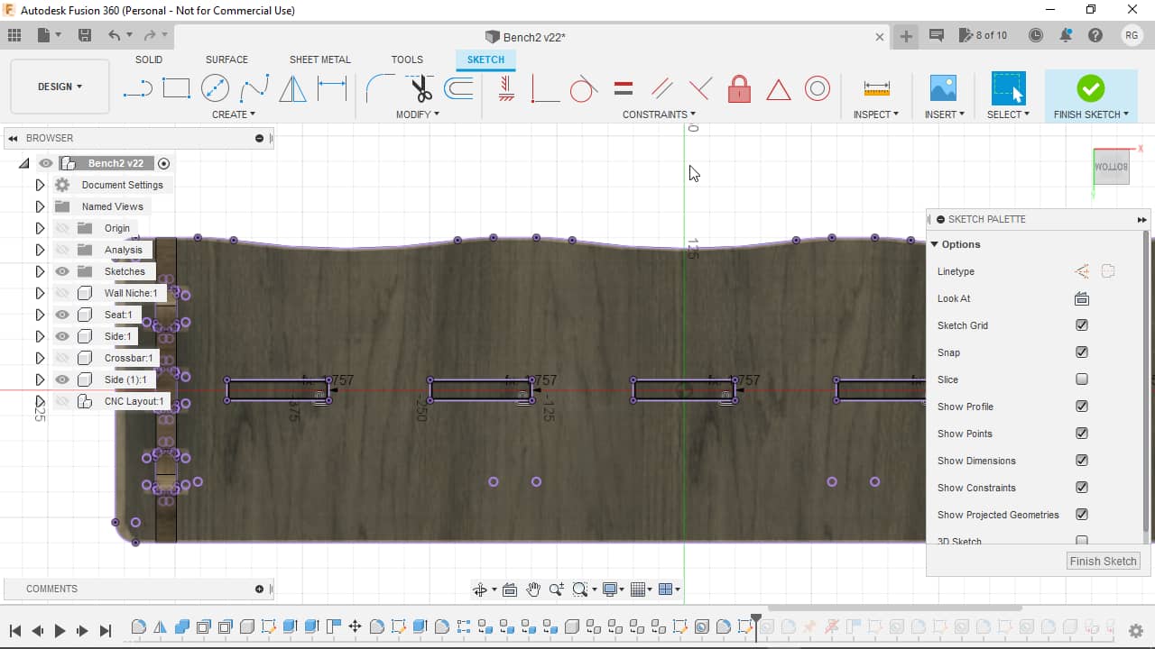
I started out by sketching the basic seat shape…
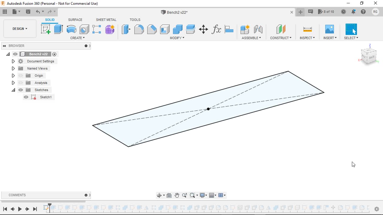
…and extruding it upwards:
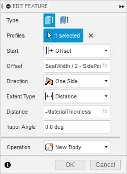
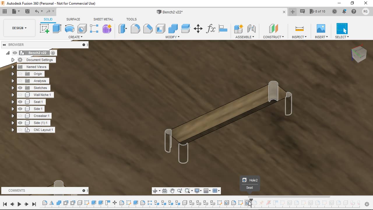
After doing so, I made a sketch in the center for the shape of the legs/sides…
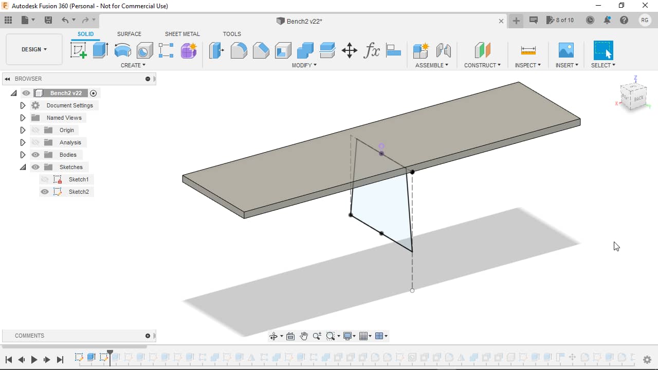
…and extruded them with an offset, so they’d end up at the sides…
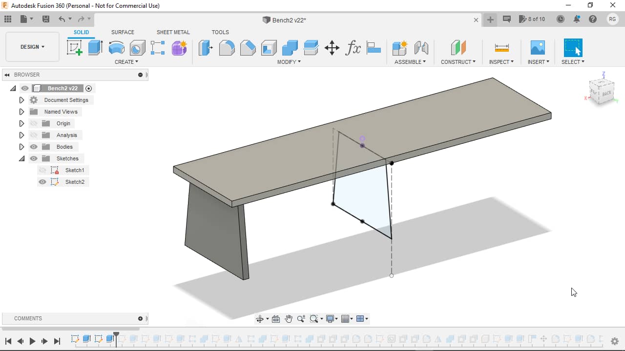
…using following parameters:
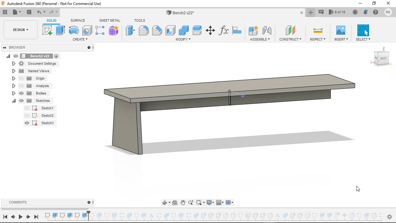
I then went on sketching the cross section of the stabilizing crossbar…
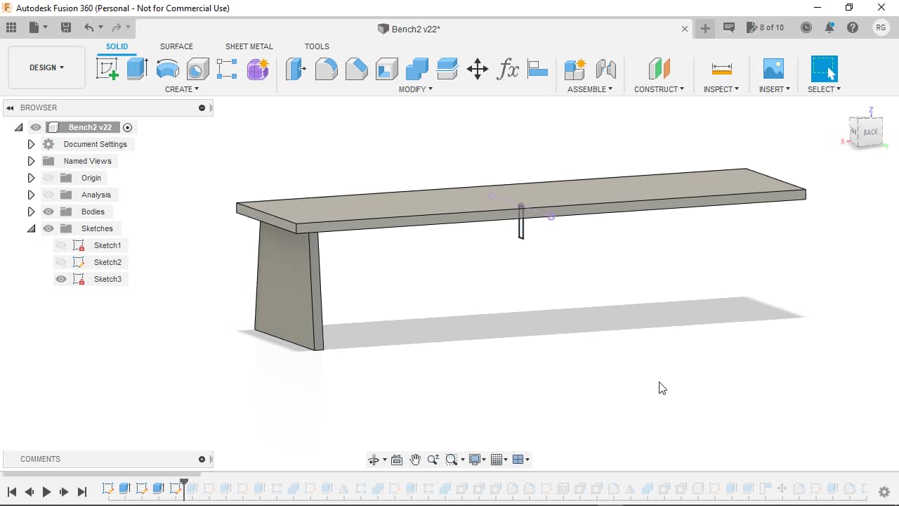
…and extruding it symmetrically to both sides:
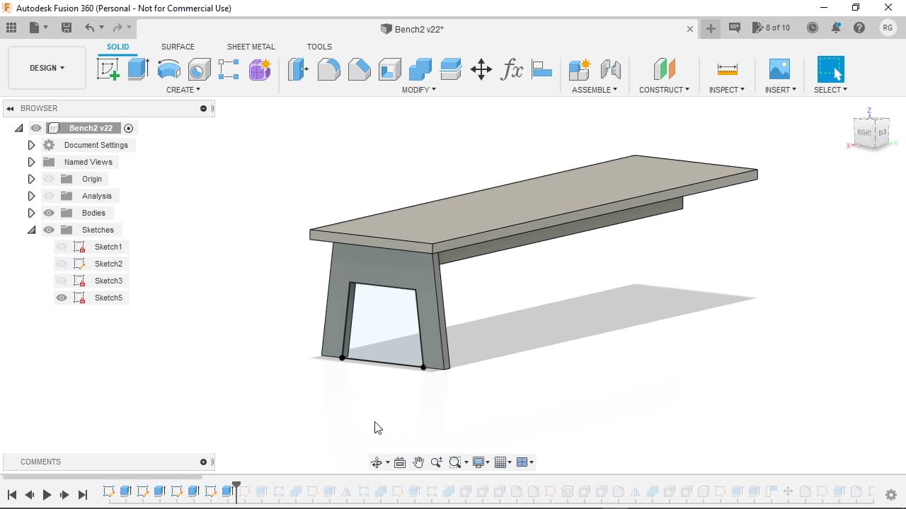
I decided to finish the one existing side as much as possible and then mirror it over to the other side. For doing so, I sketched the cutout onto the surface of the side…
…and removed the material by extruding into the side, making an extrusion cut:
Adding Finger Joints
My bench was supposed to be assembled without fasteners or glue, just with friction fit finger joints. In a preliminary test in the group project, we found out that an offset of -0.2 mm (so enlarging the hole) on all sides of the finger holes would create a good friction fit - but -0.1 mm was too tight. Since I wanted an even tighter fit than in the tests I went with an offset of -0.15 mm in the end.
Side Fingers
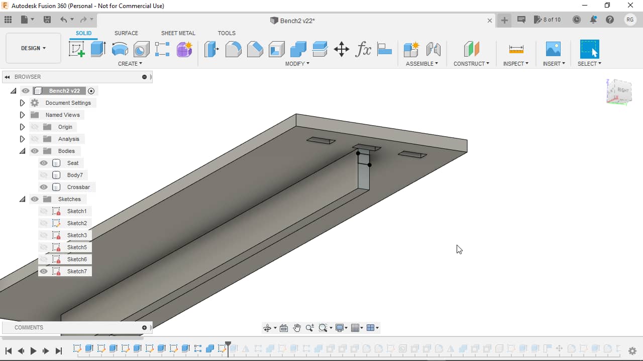
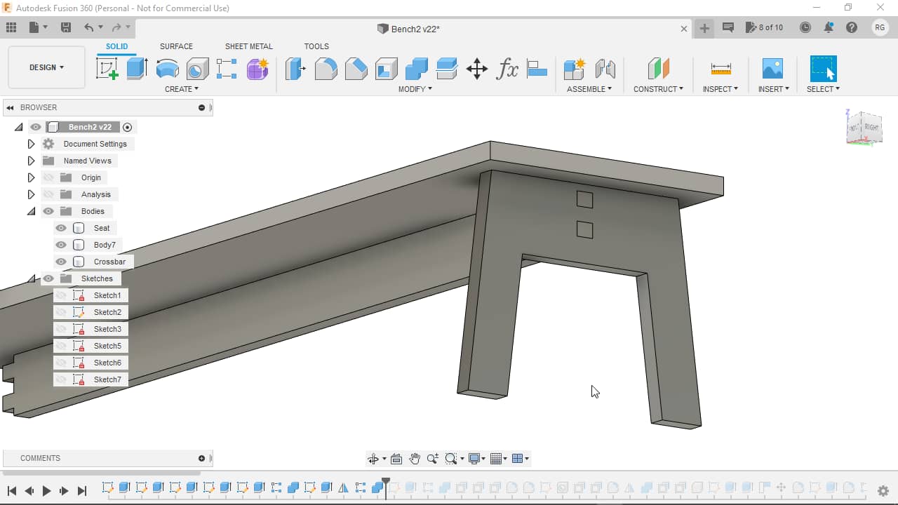
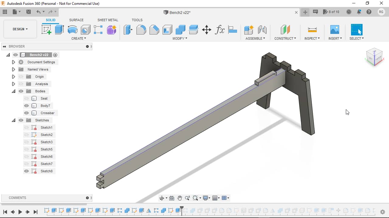
I continued by adding fingers to the top of the side panel. I started out by sketching and placing a single finger’s cross section onto the top of the side edge,…

…extruding it upwards…
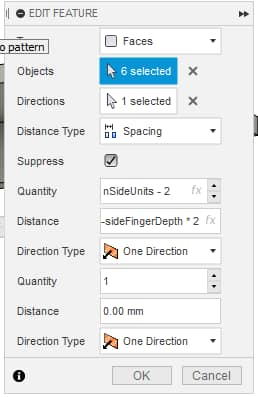
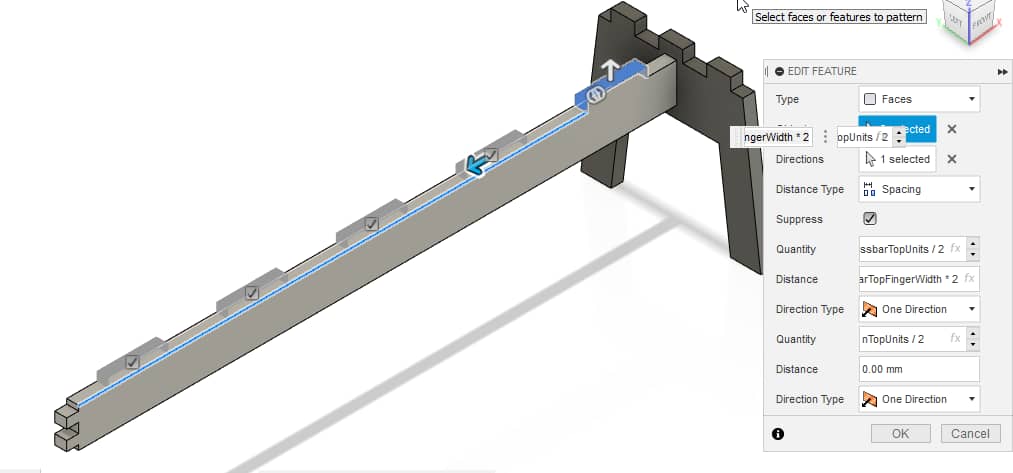
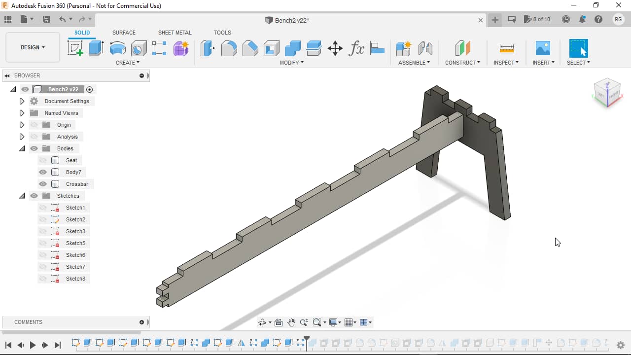
…and then patterning it using following parameters…
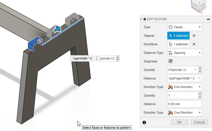
…to create repeated fingers:
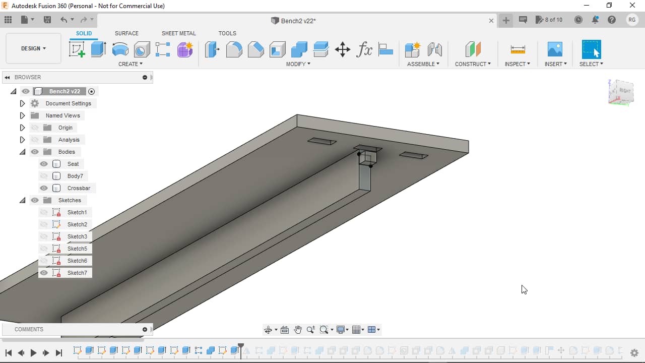
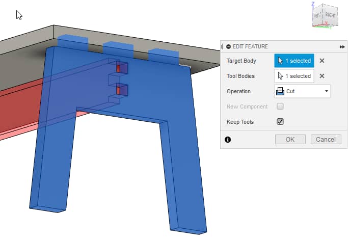
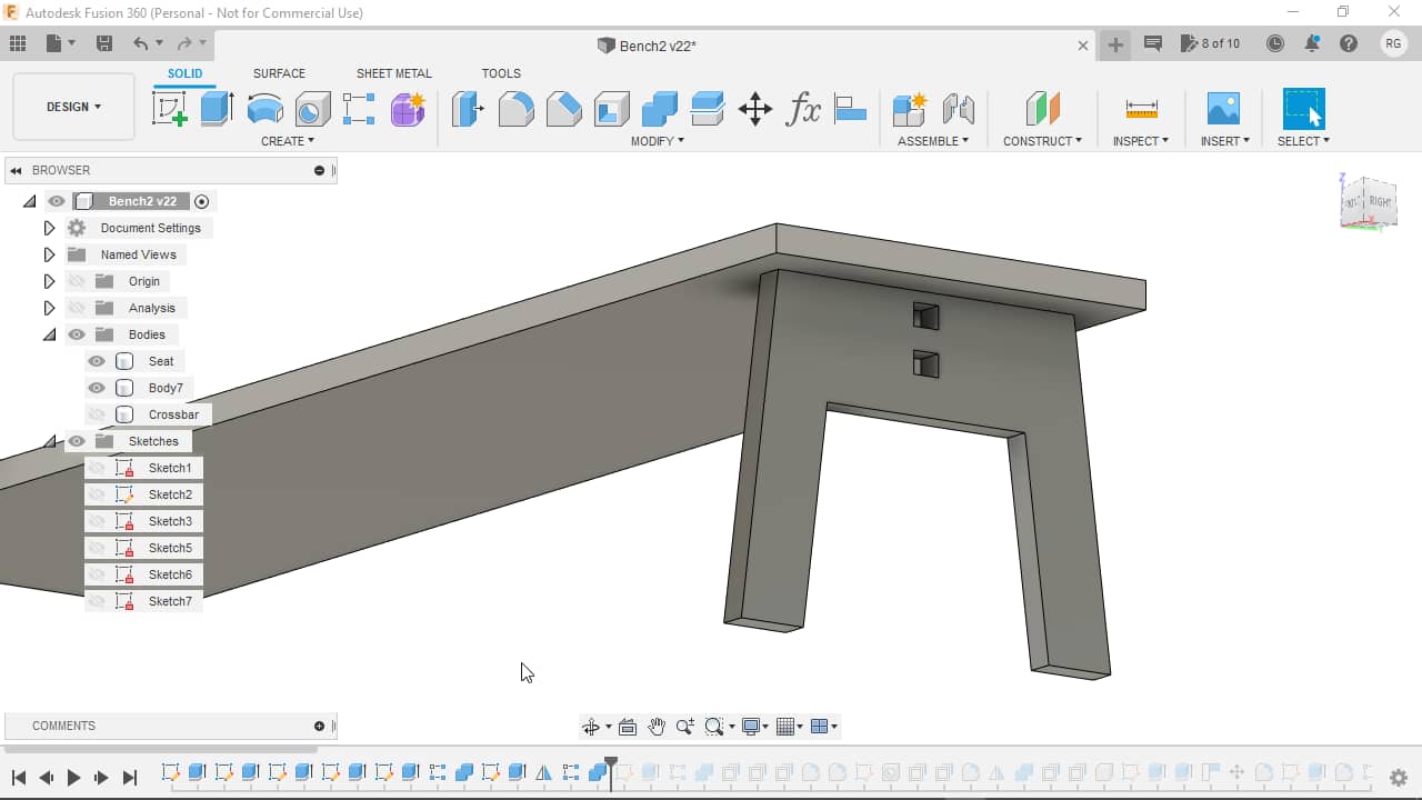
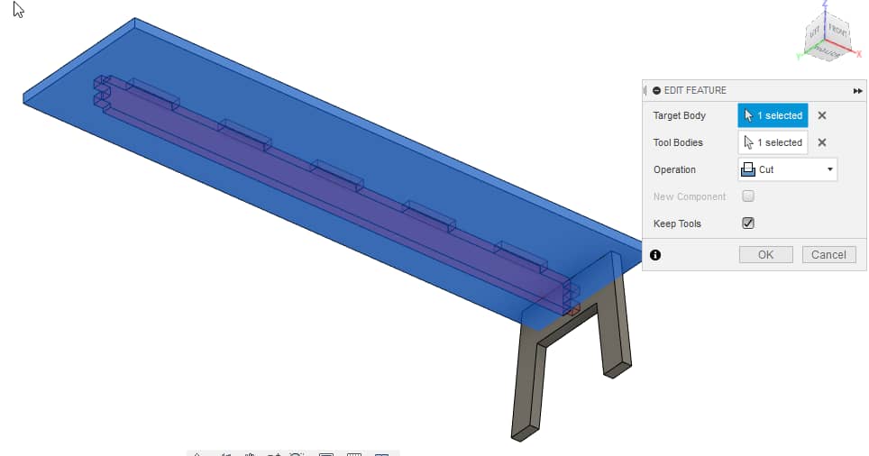
I then used the Combine function to subtract the fingers from where they intersected the seat, making sure to keep the tool bodies by checking Keep Tools…
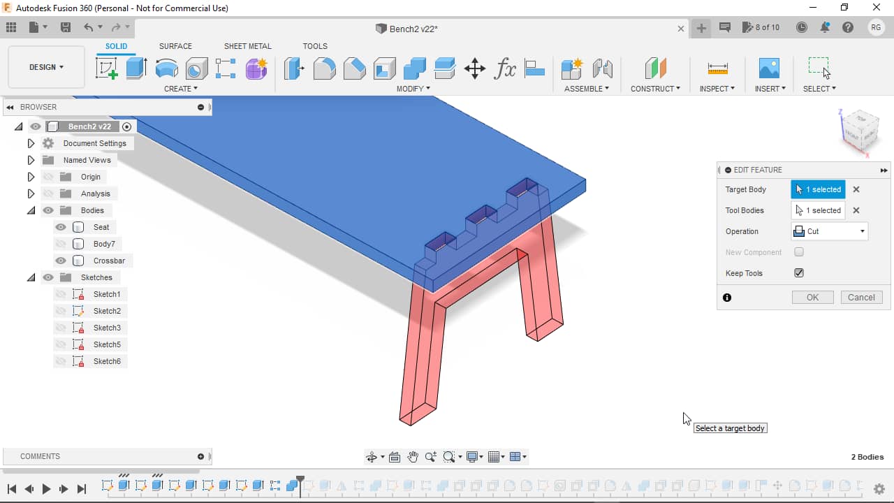
…which left the parts intersected:
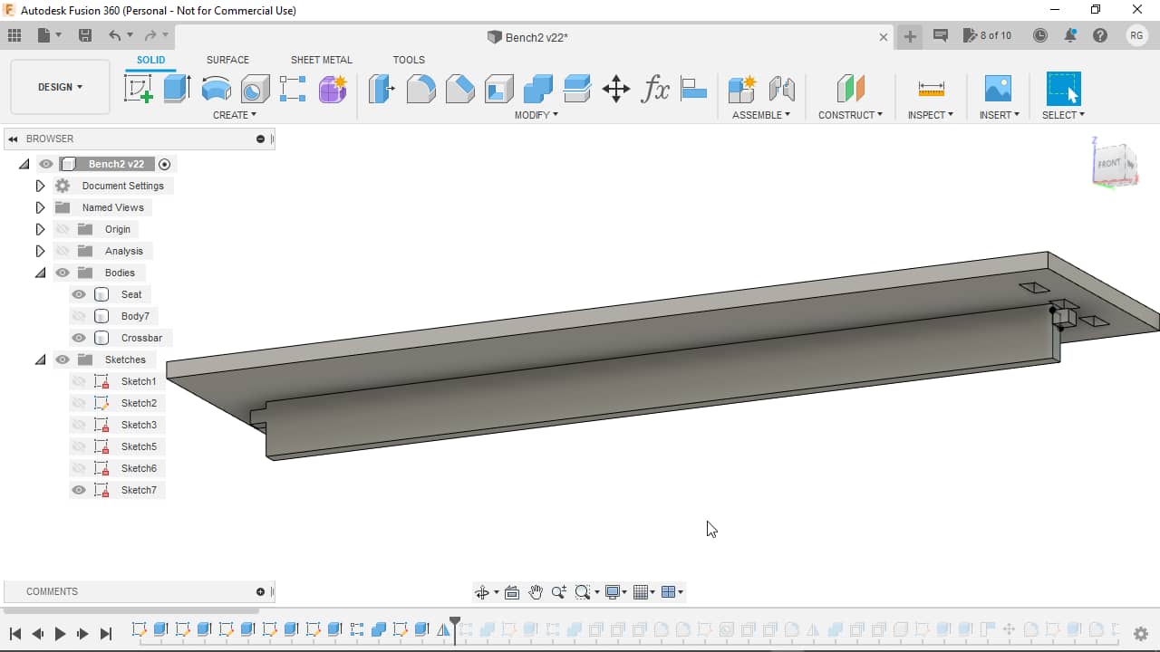
After hiding the side body, the subtraction becomes more apparent:
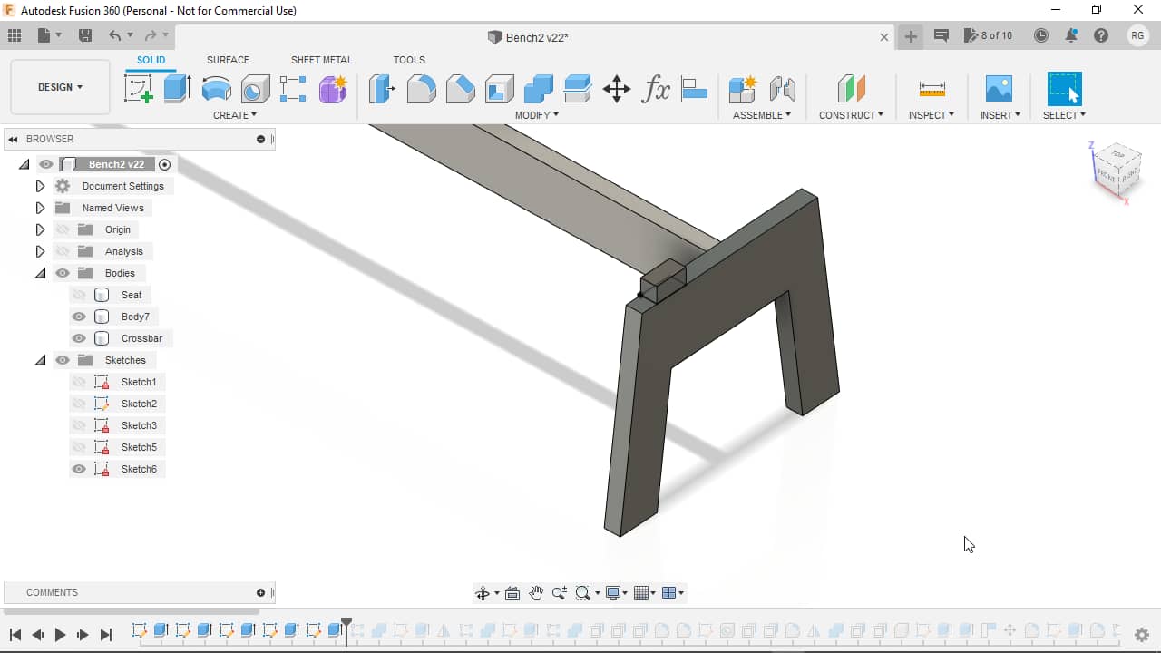
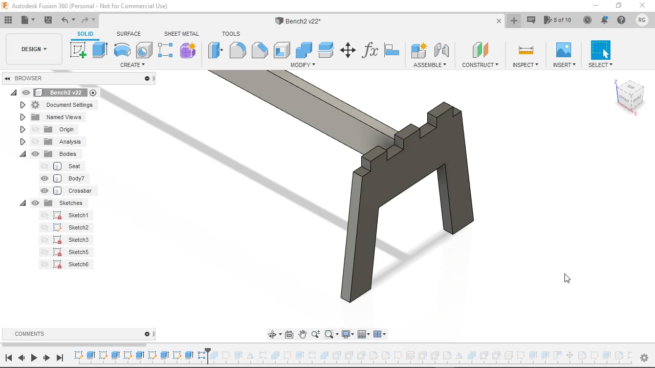
Crossbar Fingers
After finishing the top fingers, I went to work on the side fingers on the crossbar. I started out by, again, creating a cross section sketch on the crossbar side…
…and extruding it outwards:
I also immediately mirrored the extrusion to appear on the other end of the crossbar…
…and patterned it using following parameters…
…to end up with following result:

After finishing the fingers, I used the Combine function again to subtract the intersecting fingers from the side body using following parameters…
…leaving me with this result:
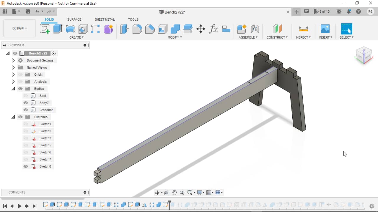
Again, the whole effect only becomes apparent once the crossbar body is hidden:
Top Fingers
For the top fingers, again, a sketch,…
…an extrusion (this time not as much though, as I didn’t want the fingers to go through the seat, but end in a blind hole/pocket)…
…and a patterning operation using following parameters…
…to arrive at this result:
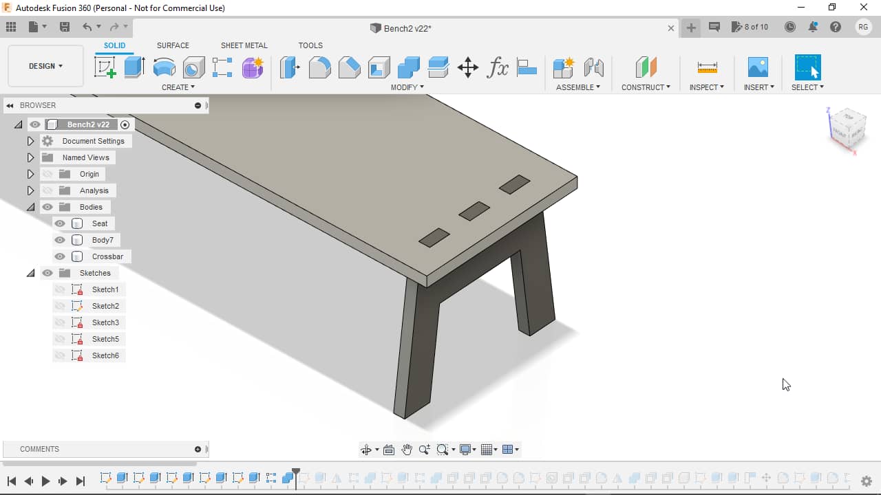
To create the blind holes for the fingers to sit in, I again used the Combine function to cut away the intersecting material from the seat body…
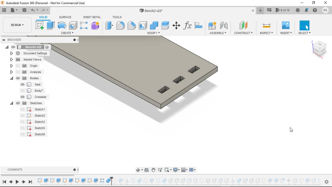
…leaving me with following result:
Here we can see the seat from underneath after hiding the crossbar, revealing the blind holes:
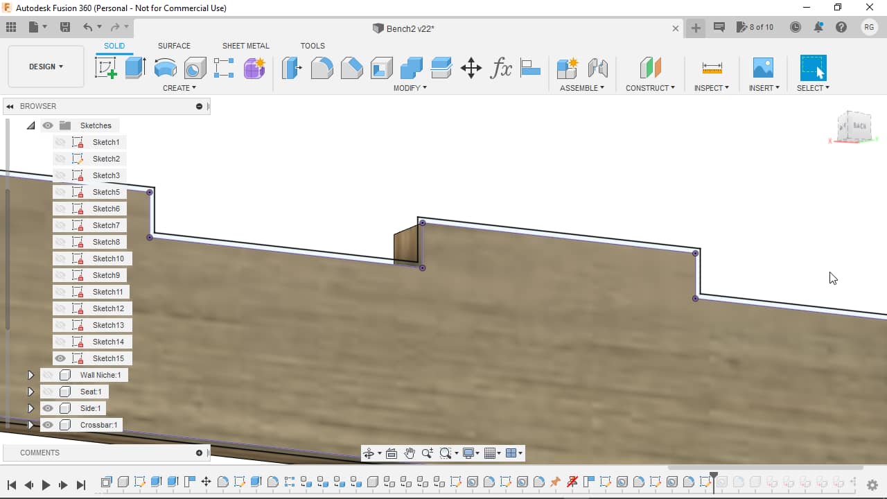
Joint Clearances
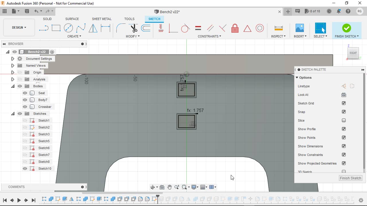
With all fingers now subtracted away from their respective counterparts, I started adding clearances to the holes. I used two different clearances: one for the direction of material thickness, which can be a bit more variable, and another one for the width of the fingers as determined by our cutting (which is more controllable for us) - in the end, both of them were set to -0.15 mm though, but they could be altered independently. I started with the offset at the cut sides of the fingers. To add offsets, I use the Press/Pull tool in Fusion 360, which can be used to offset faces in their normal direction:
![]()
I then continued by adding a clearance in the material thickness direction…
![]()
…and for the blind holes, I also added a generous clearance at the end of the blind hole, to allow the finger to slide all the way in without blockage:
![]()
Next: some cosmetics. I added fillets to both the lower…
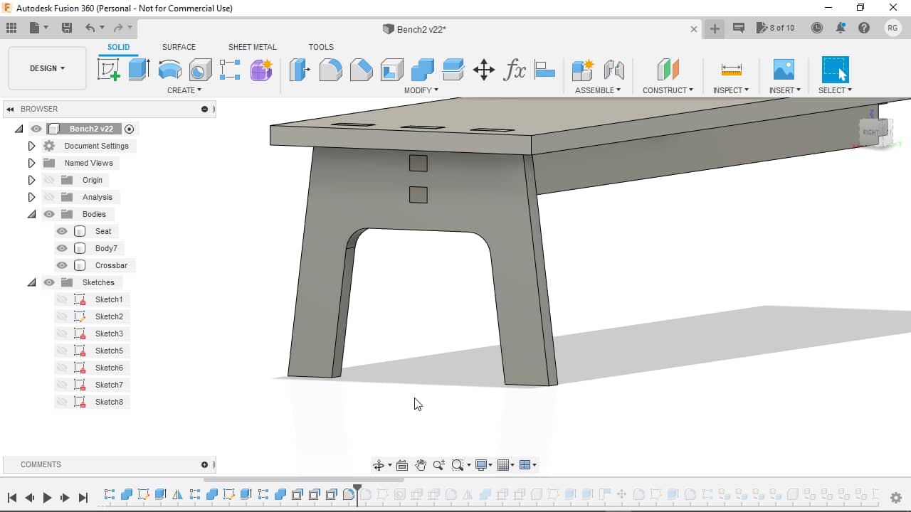
…as well as the upper corners of the sides:

Dog Bones
Since mill bits do not create perfectly sharp internal corners, I then added dog bone features to all sharp inside corners where fingers would have to assemble. To do so, I started out by adding a sketch, projecting the hole edges onto the sketch and offsetting them by a certain amount calculated in the variable perfectDogboneOffset (why it is this cryptic amount I will describe later):
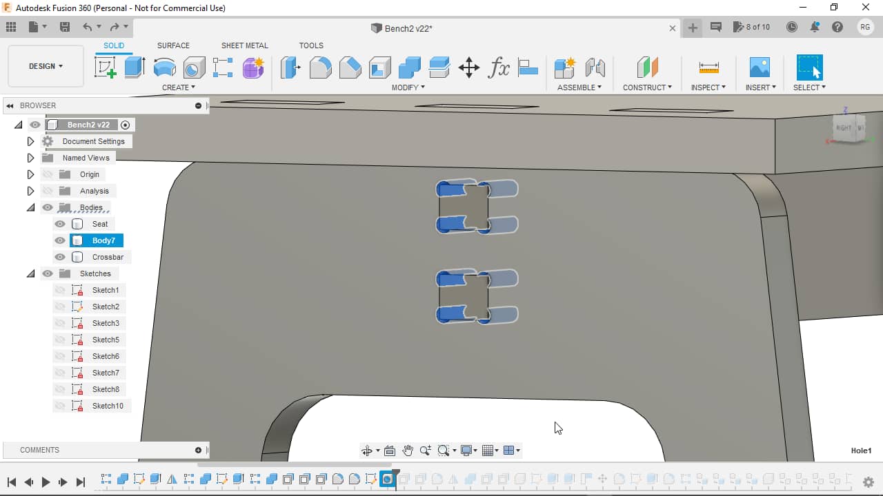
At the corners of the offset hole shapes, I added Hole features using the mill bit diameter as size…
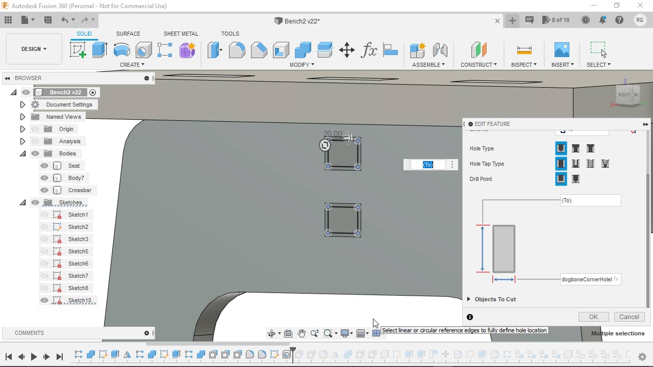
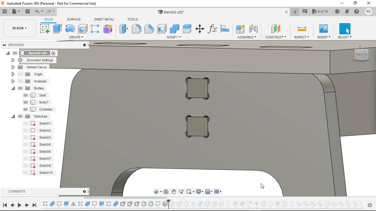
…creating following holes:
Another shot with everything in its final state:
I then went on to give the hole the same clearances as before. One for the cut direction…
![]()
…and another one for the direction of material thickness:
![]()
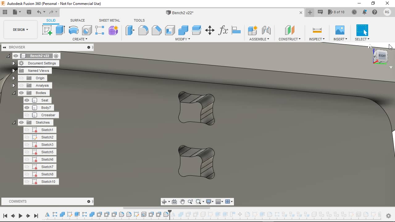
Since the CAM module can sometimes have a hard time deciding whether the mill bit can enter the corners or not, I also added a rounding fillet, which also looks nicer to me. Here’s what the shape looks without…

…and here with the fillet:
With most features on the side now finished, I decided to mirror the side to the other end to assess the bench design visually:
On the other side of the seat, the cutouts for the side’s fingers were still missing, so I added them again…
…by using the Combine function:
Here’s the result with the fingers of the mirrored side removed, too (yes, I could have removed the fingers of both sides at this point only, together, but I didn’t really see the point In fixing this in hindsight now. Never change a running system :) ):
I then added clearances to all seat holes in cut…
![]()
…and material thickness direction:
![]()
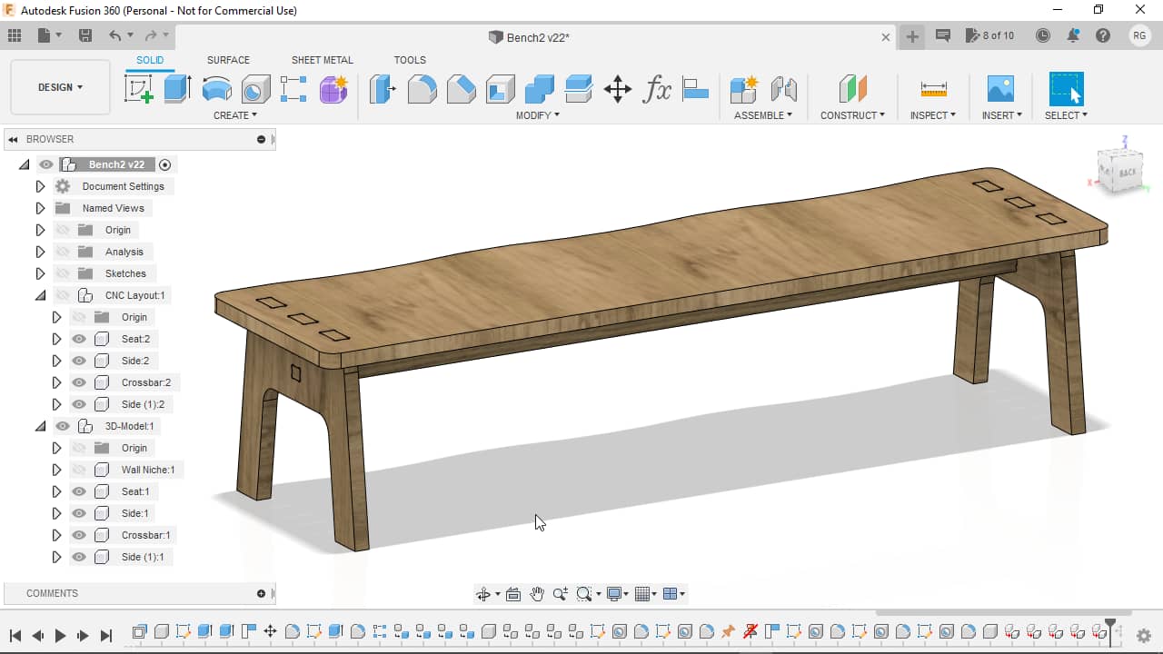
Cosmetics
With the bench more or less done, I added a model of the niche the bench was later supposed to sit in. To do so, I added a new Component and inside the component added a shape resembling the niche:
Here’s the niche together with the bench, placed relative to each other using the Move tool:
I saw that the shape was not round enough for my taste, so I added fillets to the corners of the seat, turning it from this…
…into that:

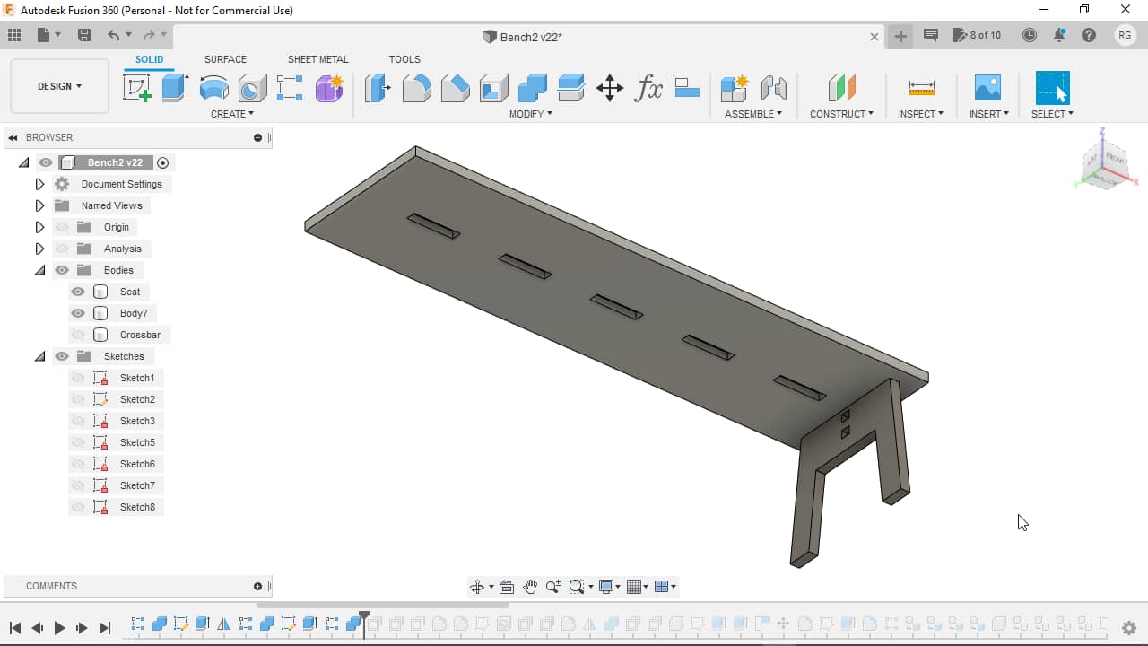
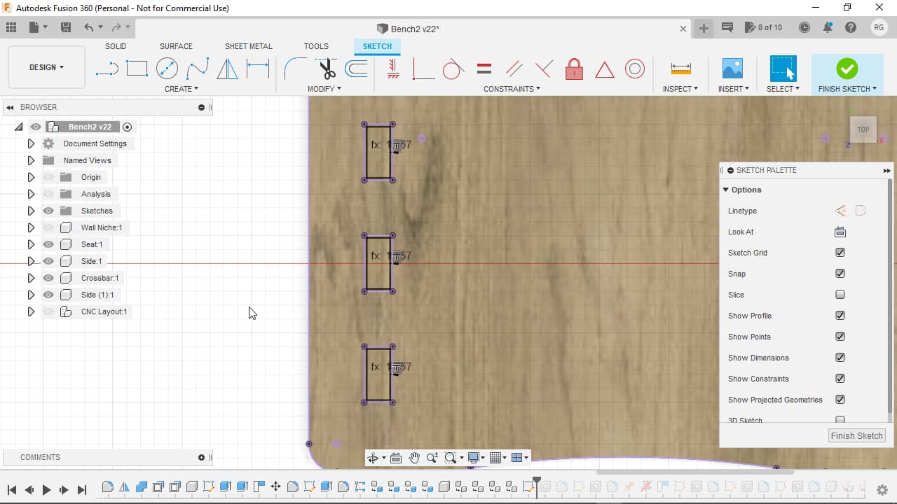
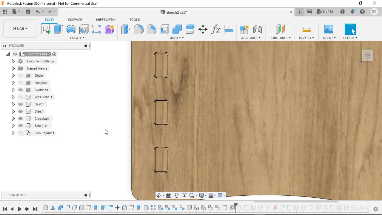
I also wanted to indicate that the bench was made to seat three little humans, so I created a very shallow, rounded cutout at the front edge of the first seat…
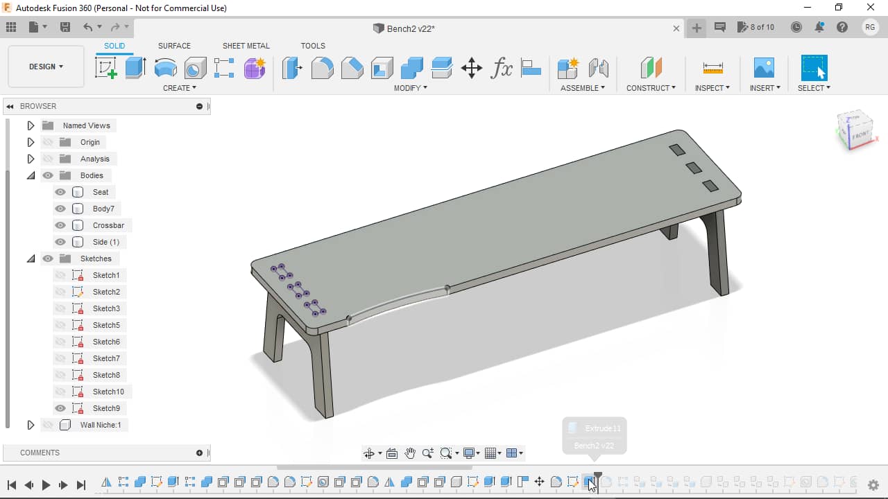
…and added fillets to all the sharp edges to smooth things over:

I then patterned the cutout linearly for the remaining seats using following parameters…
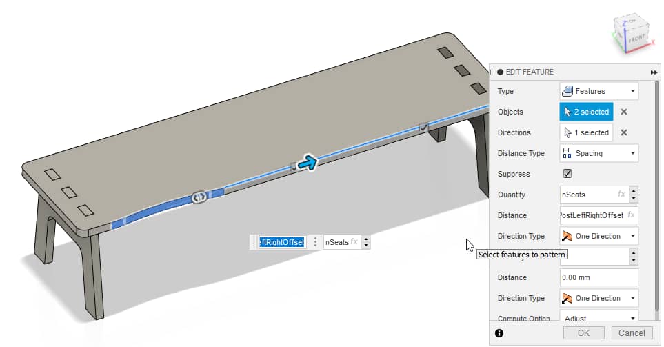
…leaving me with this result:
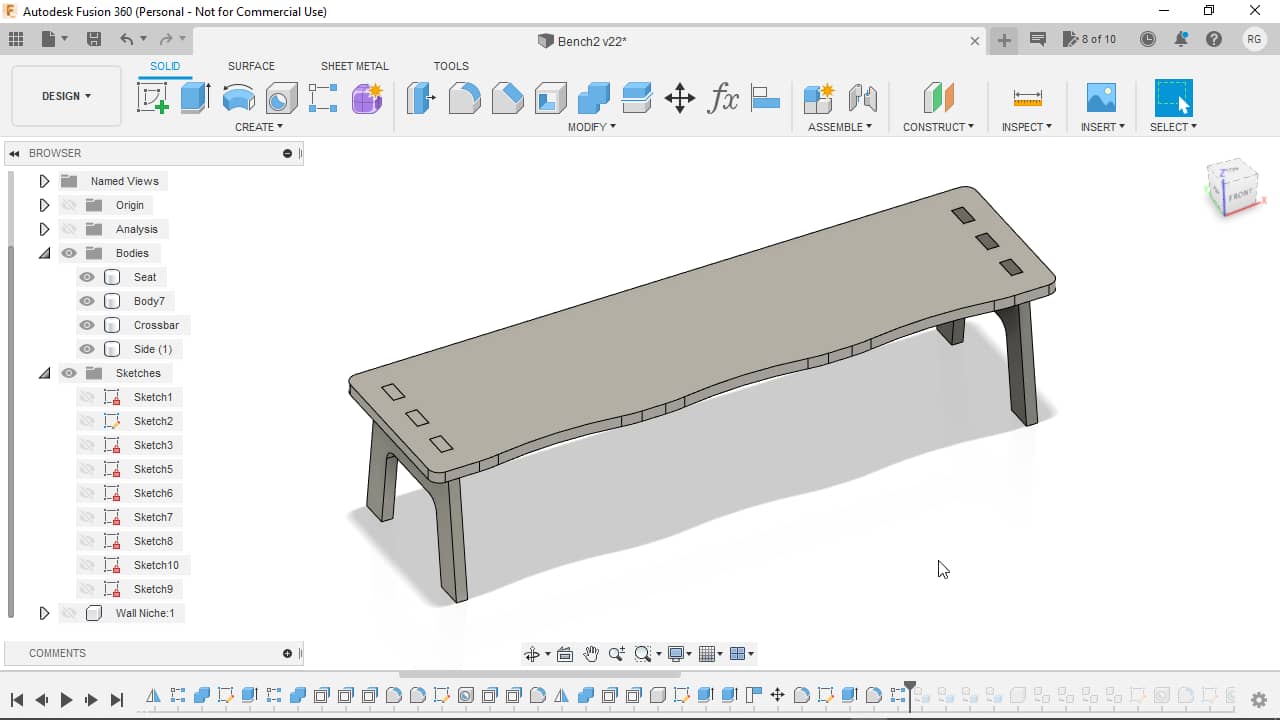
I now made all of my bodies into components and gave them a wood like appearance:

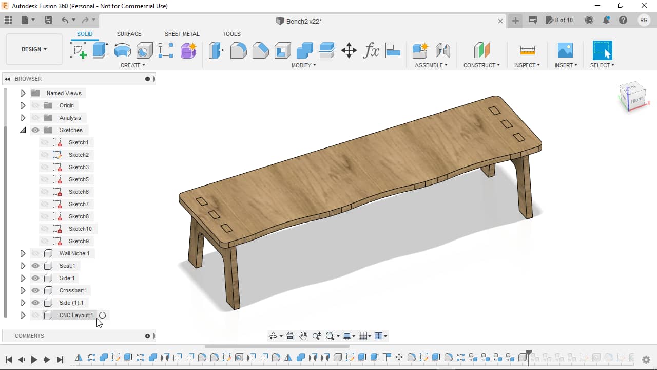
CNC Layout
For creating the CNC layout, there’s a bunch of ways. I decided for a nice way that allows for both keeping the 3D-model as designed, but at the same time getting a usable CNC layout out of it. This works by making a new component for the CNC layout and then copying all the design components into it and distributing them as needed. The original design’s components can be kept in their original configuration to reflect the 3D-design. When changes are later made to the components of the 3D-model, the copied components in the CNC-layout are automatically updated as well, as they are linked by default. To begin the process, I added a new component for containing the CNC layout:
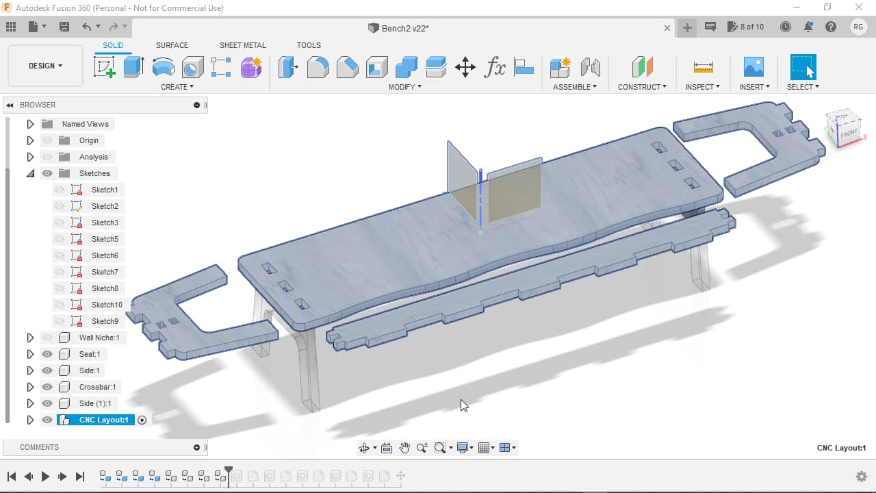
I then copied all of the components (1x seat, 1x crossbar, 2x sides) over into the CNC layout component and aligned them roughly using the Move and Align tools:
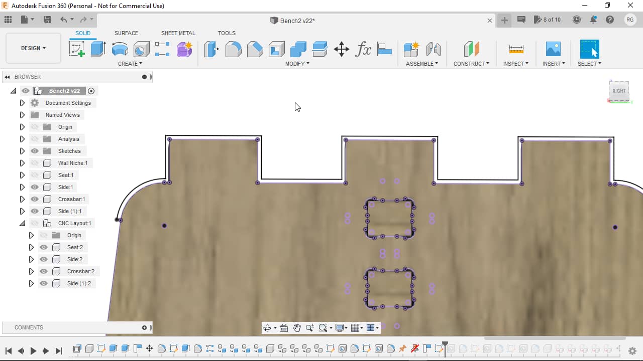
I then added dog bones to the holes in the seat by offsetting the holes in a sketch…
…making holes in the corners of the offset shape…
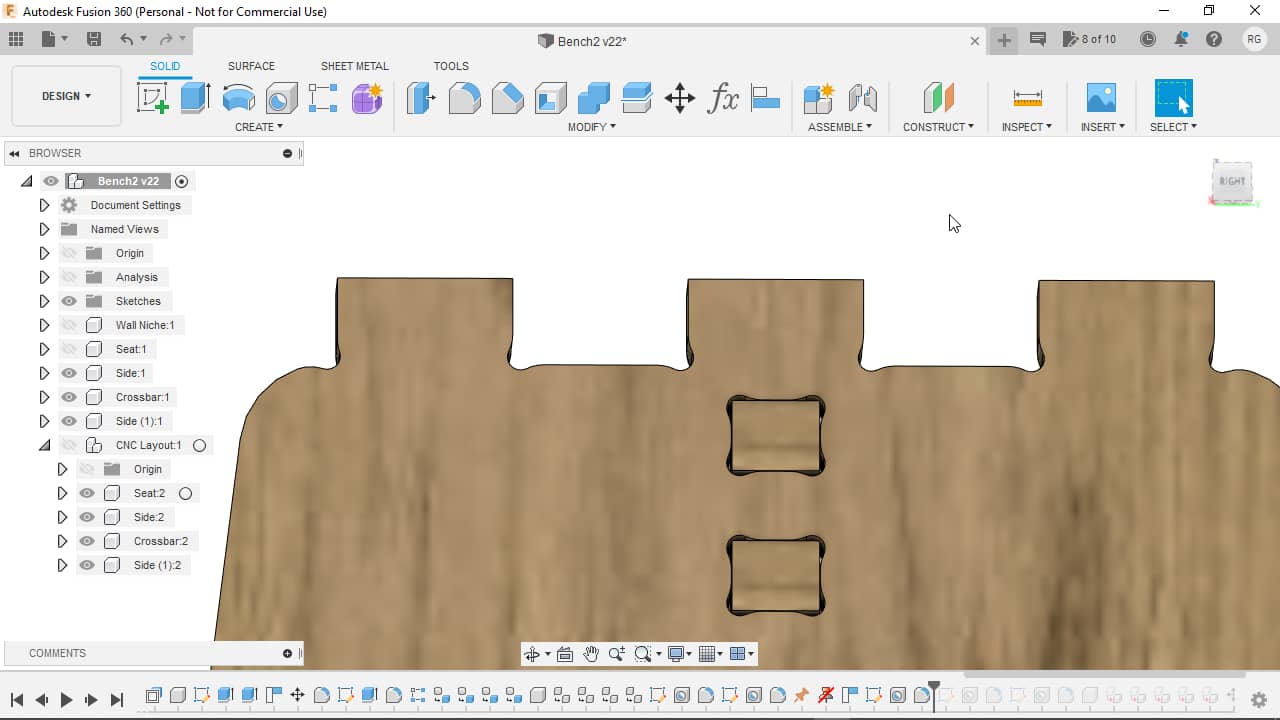
…and filleting the sharp edges of the dog bone hole:

I repeated the same process for the blind holes: Sketch with offset,…
…holes…
…and fillets:
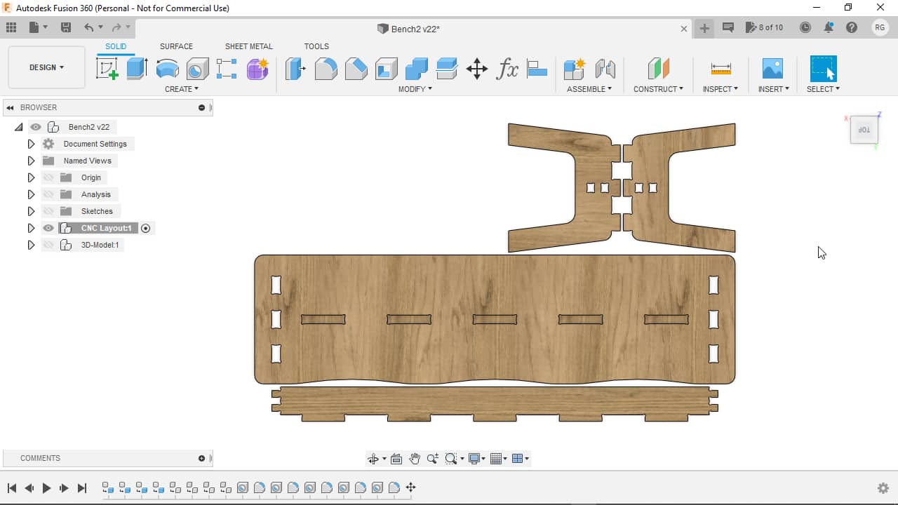
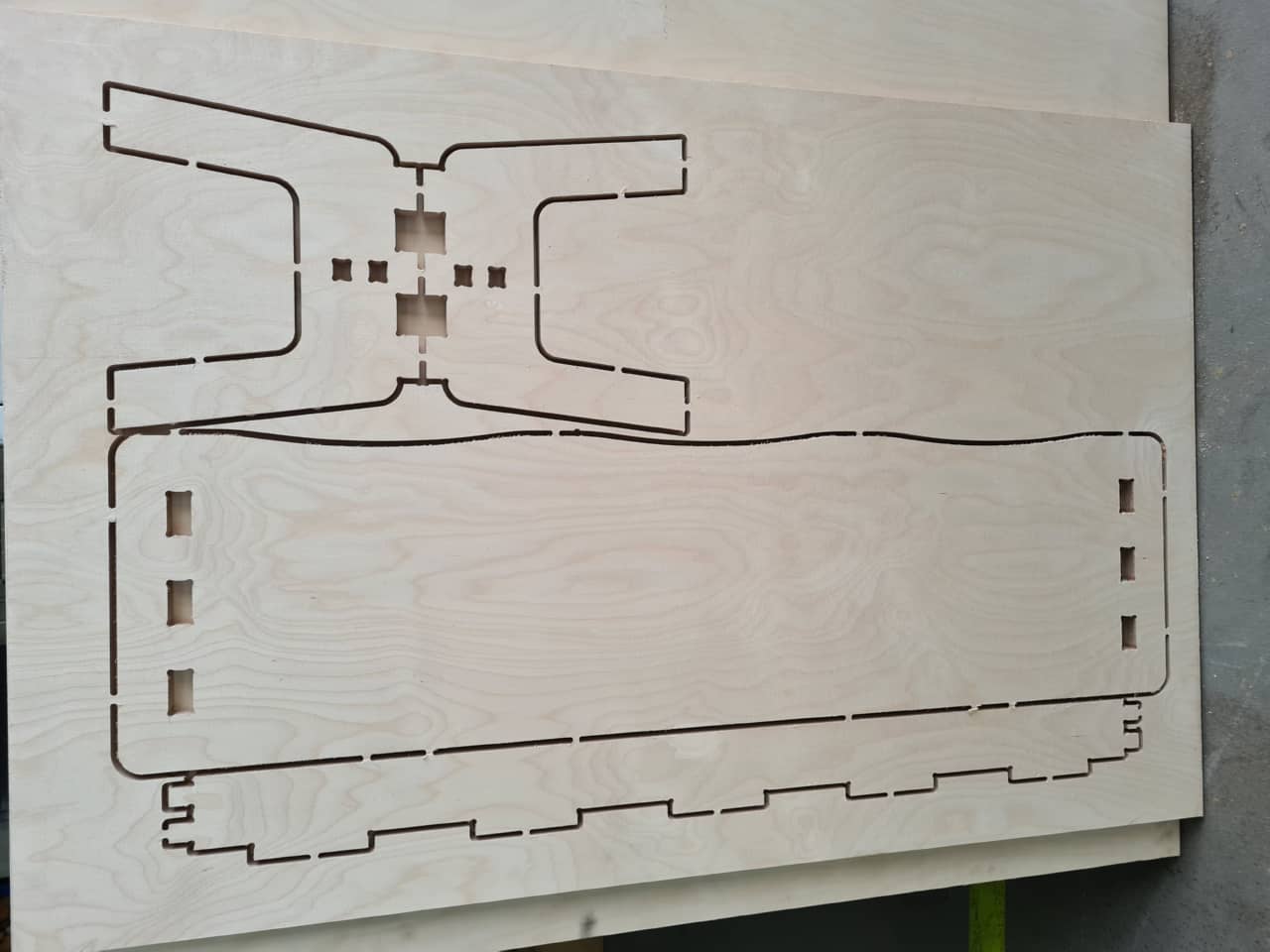
After doing so, I went ahead and cleaned up my CNC Layout to take up less space and fit a board I had available from leftovers of my colleague Aaron. Between long contour lines (like between crossbar and seat) I left a 7 mm gap so the 6 mm mill bit could move freely in between and bot contours could be given a nice surface. The sides I decided not to place intertwined, as that would have ended up too wide for the leftover board I had. I just placed them with the fingers against each other:
Fast forward a few hours: This does not chronologically fit here, as it is a fix I added afterwards, but while milling I noticed that I had forgotten corner dog bone on my male fingers. D’oh! I added dog bones to the male features using the same sequence as before, just offsetting shapes outwards instead of inwards. Sketch with offset,…
…holes and fillets:
I then fixed the crossbar fingers in the same way: Sketch with offset…
…then holes and fillets:
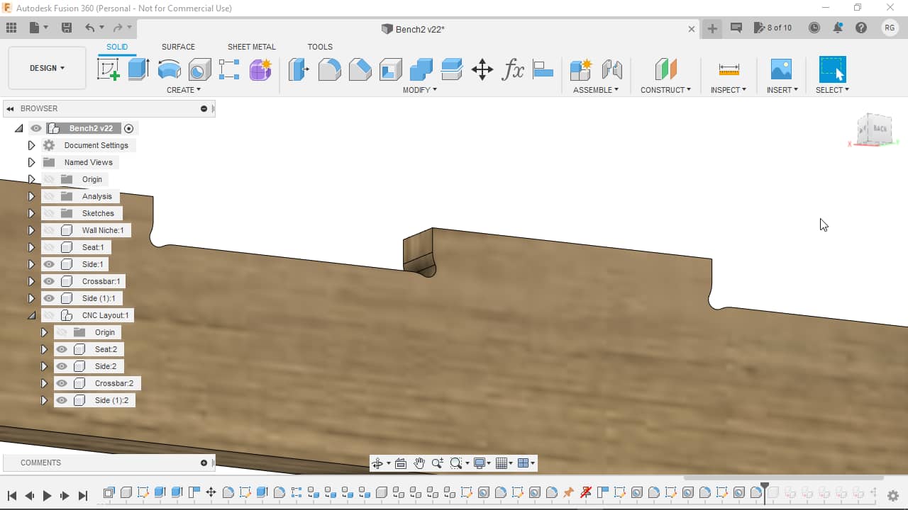
File Structure Reorganization
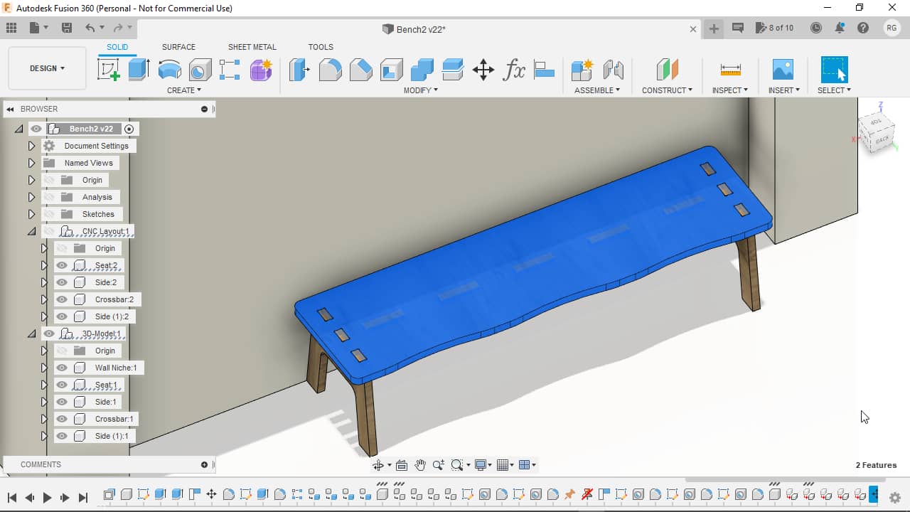
In the very end, I also added a dedicated component for the 3D-model…
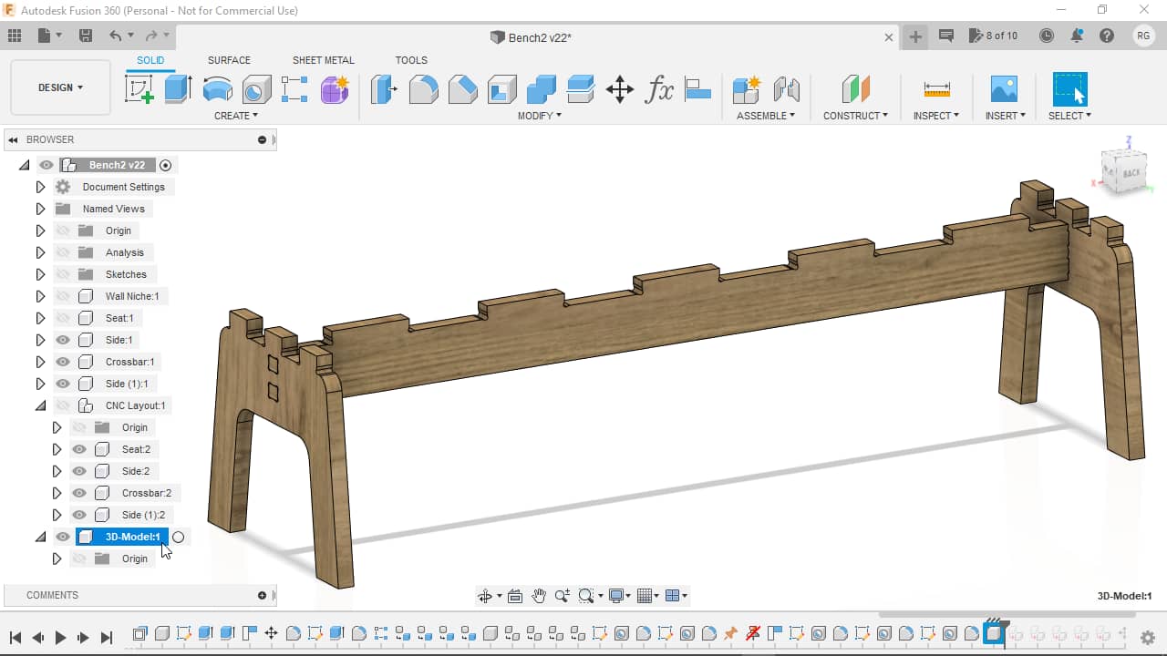
…and moved all the “normal” components into there (so I could quickly toggle visibility between the 3D-model and the CNC layout:
After toggling visibility on the niche again, I noticed that I had made the seat cutouts on the wrong side:
To fix, since the rest of the bench was symmetrical, I simply rotated the seat 180°:
CAM - Creating Cutting Tool Paths
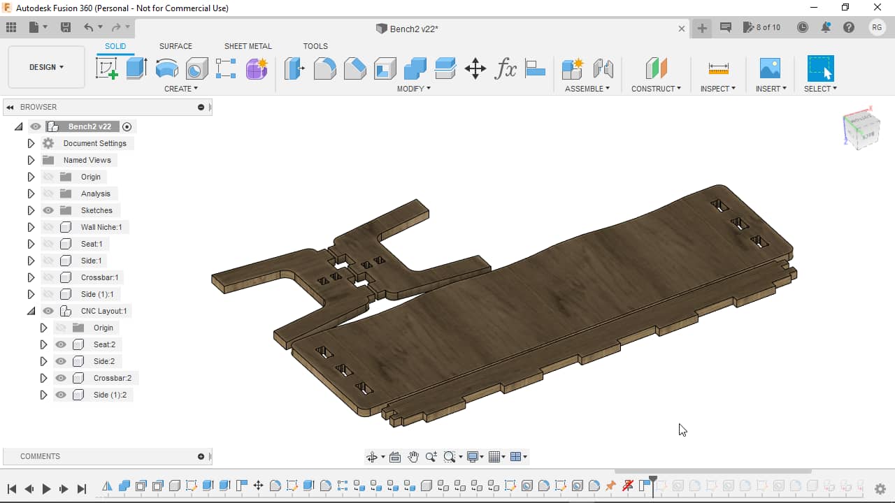
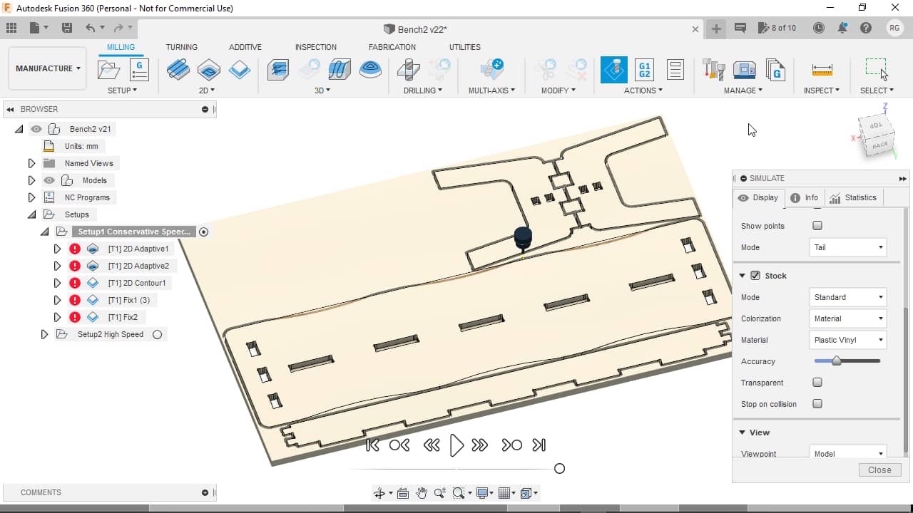
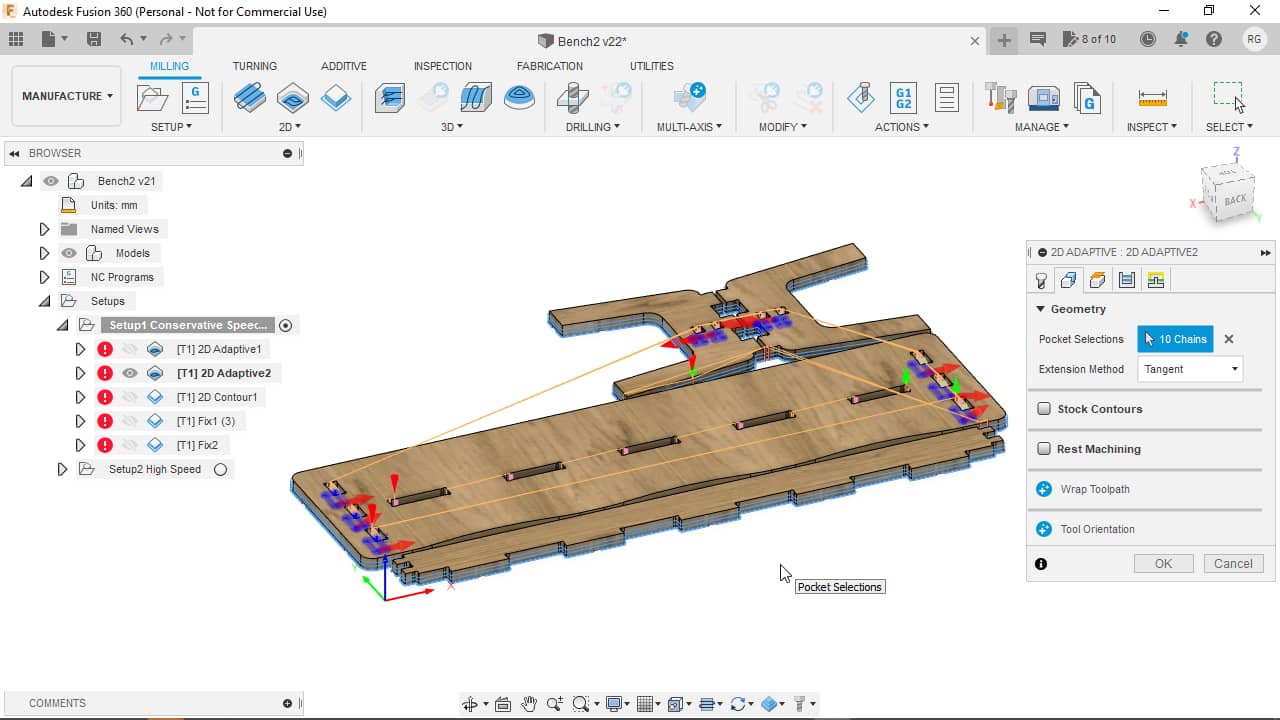
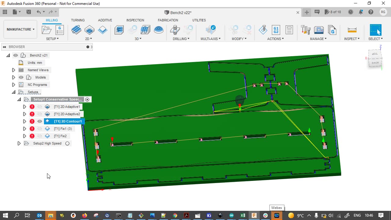
Now it was time to finally create the CAM job for cutting my parts on the CNC machine. Here’s an overview of the finalized CNC layout in the end…
…and the main tool paths we will arrive at soon, in the Manufacture workspace:
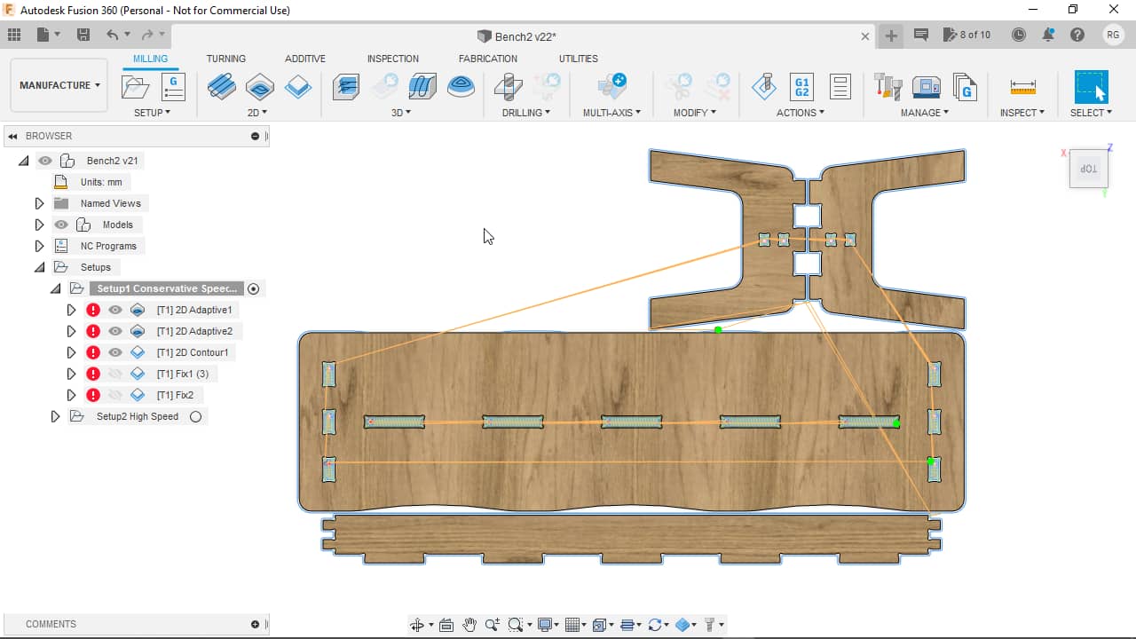
This next overview shows the parts as removed from a surrounding piece of stock:
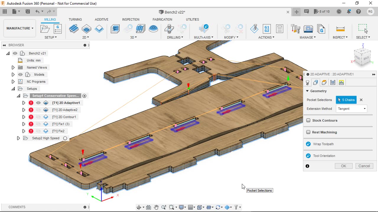
Pockets
In my CAM job, I started with the internal features. The contour would be cut at the very end to avoid material movement during the job. The very first operation was to mill the pockets. I chose a 2D Adaptive Clearing operation in Fusion 360 for this cut. Adaptive clearing kind of nibbles away all the material out of the slot in an algorithmically optimized way. The following shots show how the mill bit will remove the material in both a schematic…
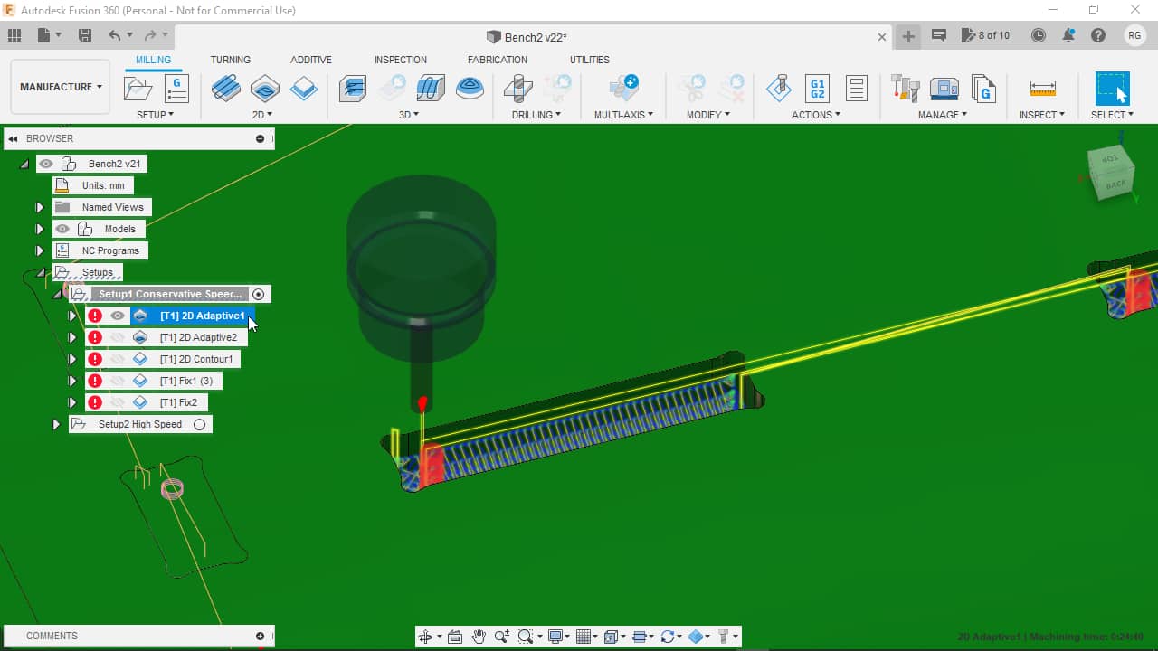
…as well as in the final view:
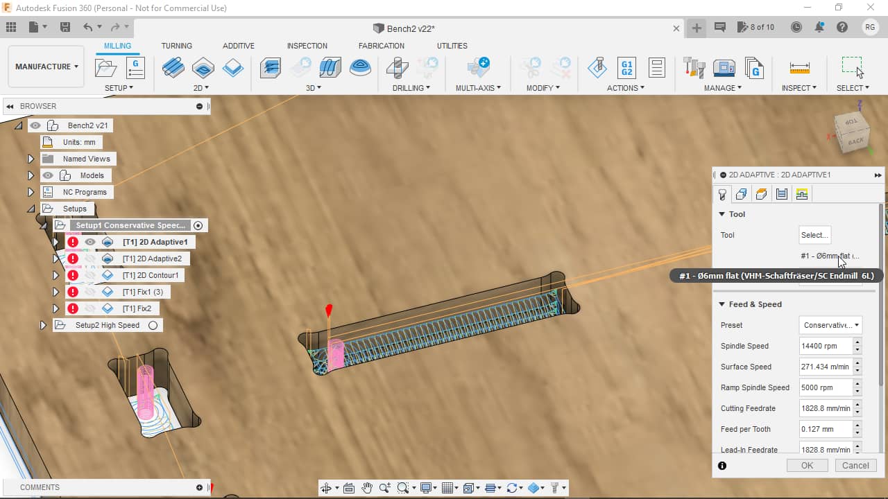
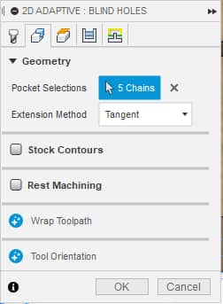
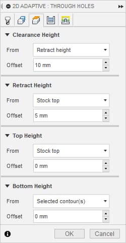
Here’s the detailed parameters for the pocket operation: Tab 1,…
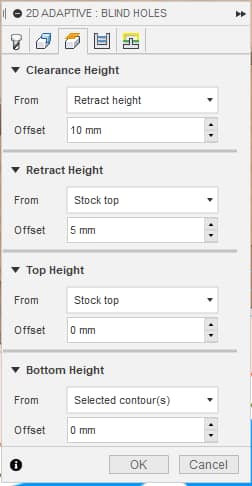
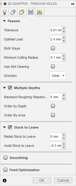
… Tab 2,…
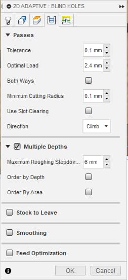
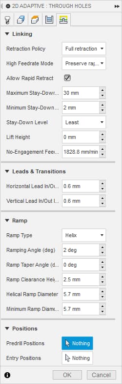
… Tab 3,…
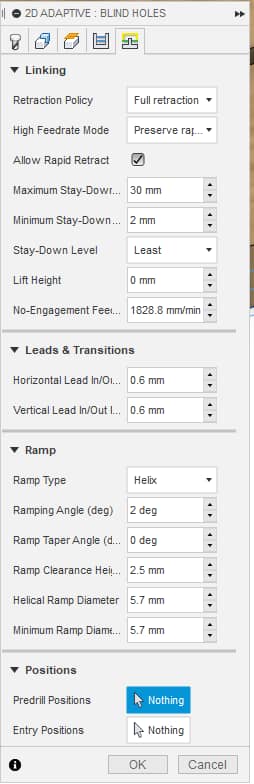
… Tab 4…
… and Tab 5:
For the pocket operation I chose the bottom edges of my pockets as targets:
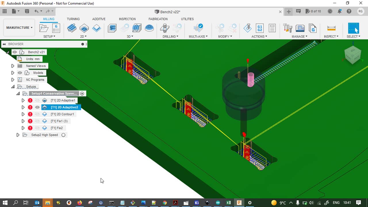
Holes
After milling the pockets, I wanted to mill the internal through holes. Not much material would be left with these small holes if I only did the contours of the holes. I would also have to put holding tabs into the through holes, which did not sit well with me, as these holes are used for the friction fit later. I really did not want to to any intricate clean up in these holes. I thus decided to use a 2D Adaptive Clearing operation again to remove all the bulk material from the hole, leaving nothing behind. Here is, again, a schematic overview of the cut:
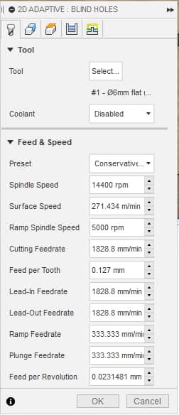
Here’s the detailed parameters for the through hole operation: Tab 1,…
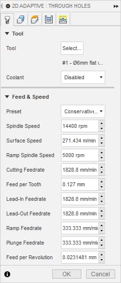
… Tab 2,…
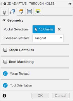
… Tab 3,…
… Tab 4…
… and Tab 5:
For the hole milling operation, I selected the bottom edges of all the holes in my design. Note that these holes were milled with a negative Axial Stock to Leave to cut all the way through the material and slightly into the underlay:
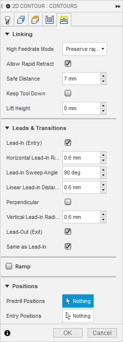
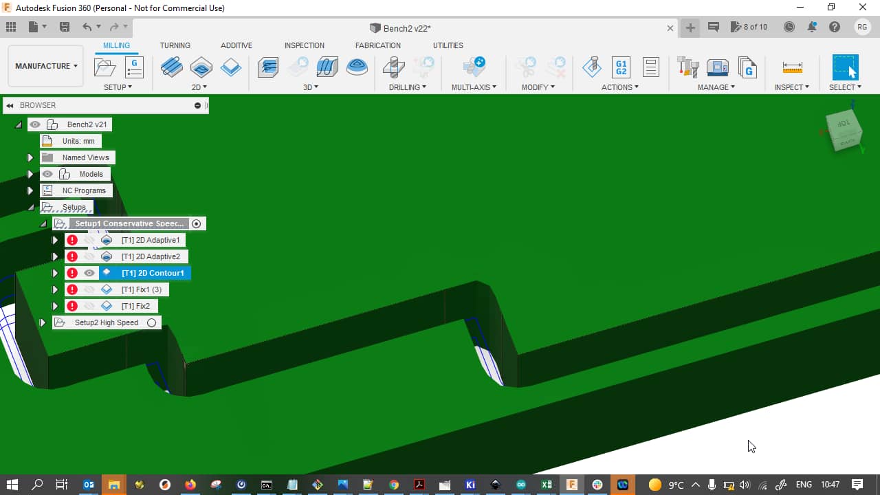
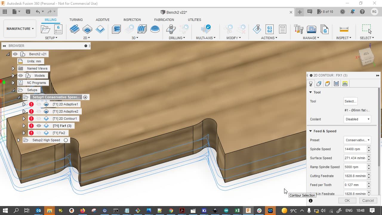
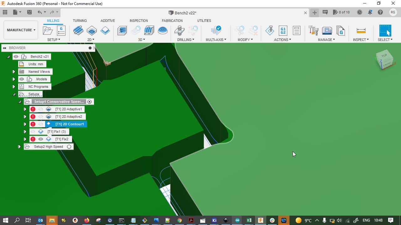
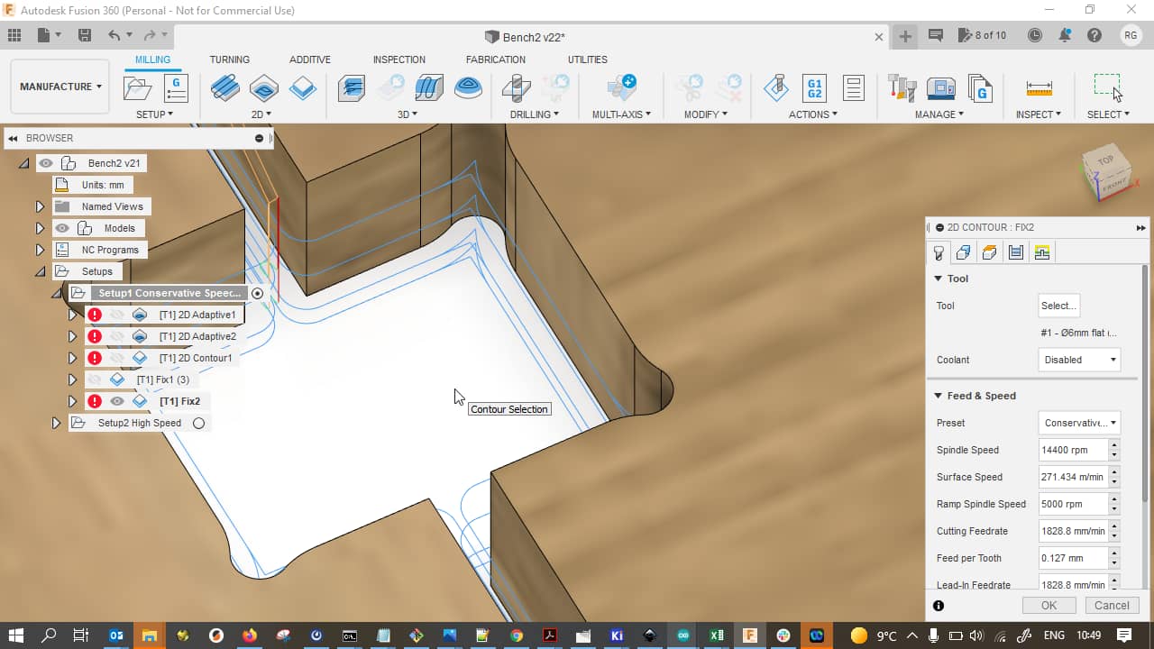
Contours
The last operation was milling out the pieces from the bulk material so they could be removed and assembled. For this, I used a 2D Contour operation. Here is an overview of the contour cuts:
Here’s the detailed parameters for the contour operation: Tab 1,…
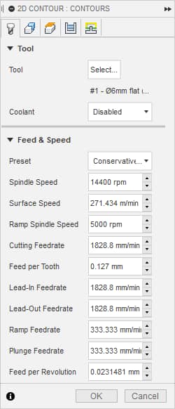
… Tab 2,…
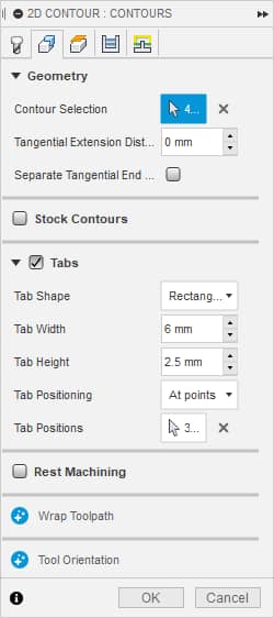
… Tab 3,…
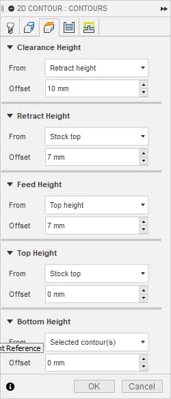
… Tab 4,…
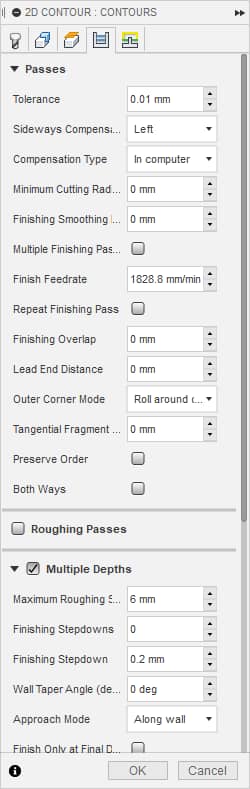
… Tab 4 (continued)…
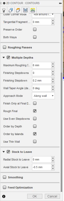
… and Tab 5:
For this operation, I selected all bottom edge contours in my design. Again, the Axial Stock to Leave was set to a slightly negative value to explicitly cut all through the material and into the underlay:
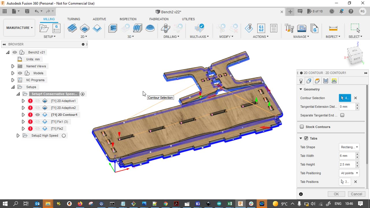
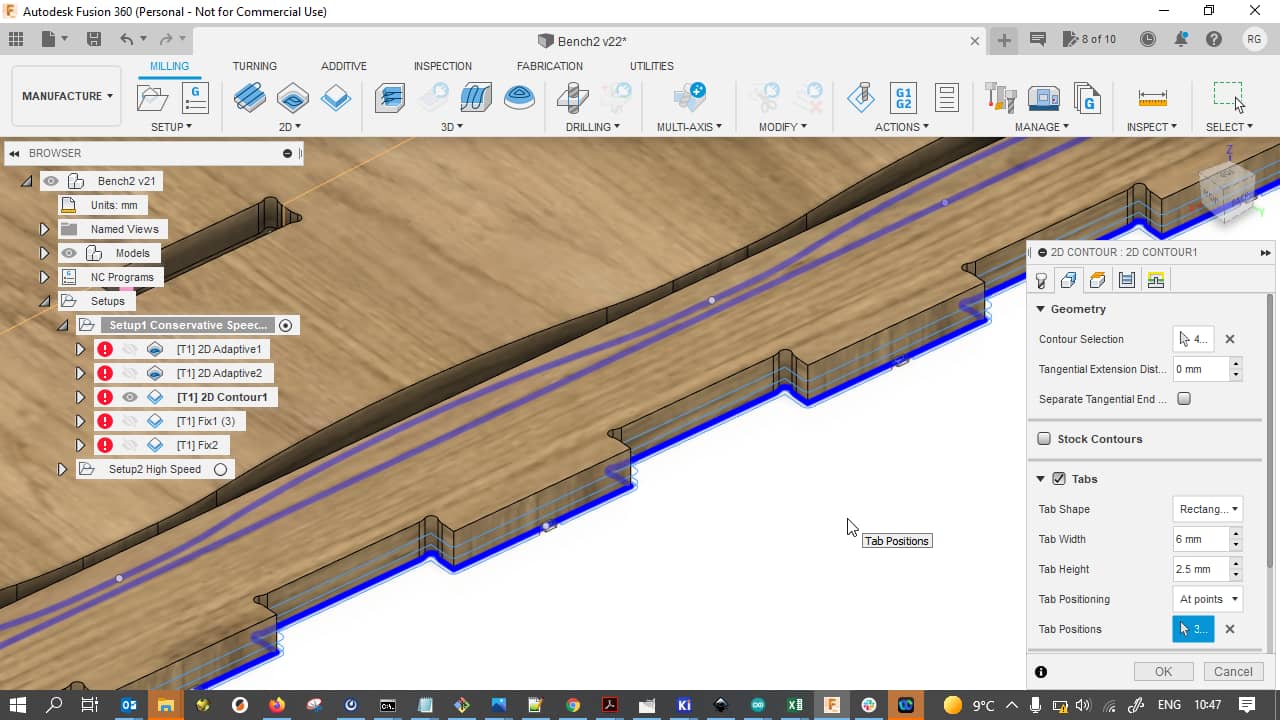
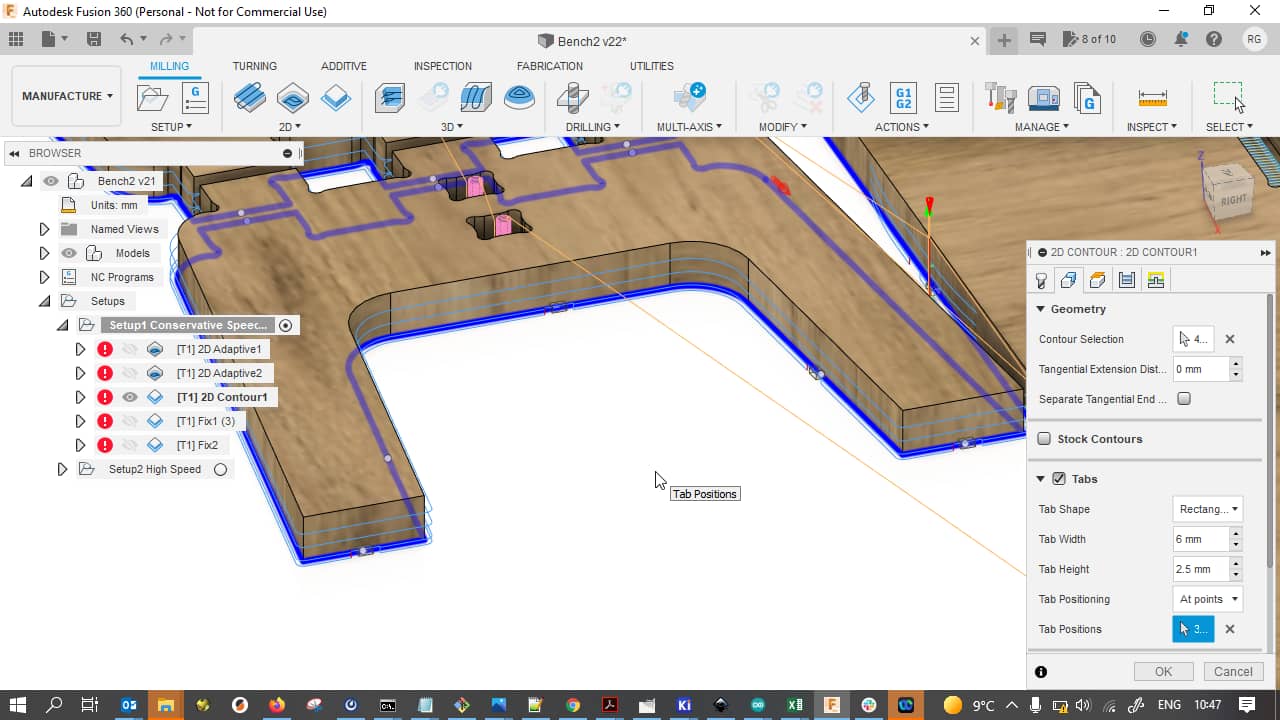
Tabs
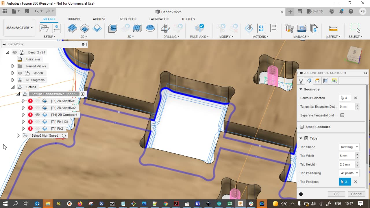
Since parts can be dislodged by the cutting forces if the whole contour is removed, it is a good decision to leave some tabs at the very bottom of the cut. These tabs hold the bulk material while the contours are being cut and can - if proper settings are used - be removed using saws or chisels later. With the Multiplex material I was using, I went for tabs of 2.5 mm thickness, which gave me 2 layers of the Multiplex in height, thereby covering both wood grain directions (tabs can become very weak when only one layer of material is left and the contour cut runs parallel with the tab’s wood grain). The width I chose arbitrarily to any value smaller than the width of the chisel I was going to use to remove the tabs later. While automatic tab placement (by spacing, e.g.) does exist, I placed all my tabs manually so they wouldn’t end up in curves or other hard to clean areas:
On the sides, I put some more tabs…
…but forgot a few tabs on the small squares between the side pieces - fast forward: these will dislodge later when cutting!
Fixes
Fast forward some more: After actually cutting my pieces (but with the job still on the machine and with my coordinate system still in place), I noticed that I had forgotten dogbone rounded corners at the finger corners, d’oh!
I quickly fixed these by adding dogbone holes as described previously and simply rerunning the cut job on the whole contour, cutting air 98% of the time and only adding the little dogbone cutouts:
This also applied to the side pieces, so I also added the dogbones here…
…for following result:
CAM Setup
Here is an overview of the CAM setup I used in Fusion 360…
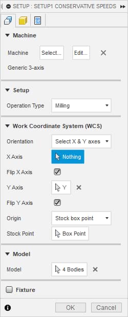
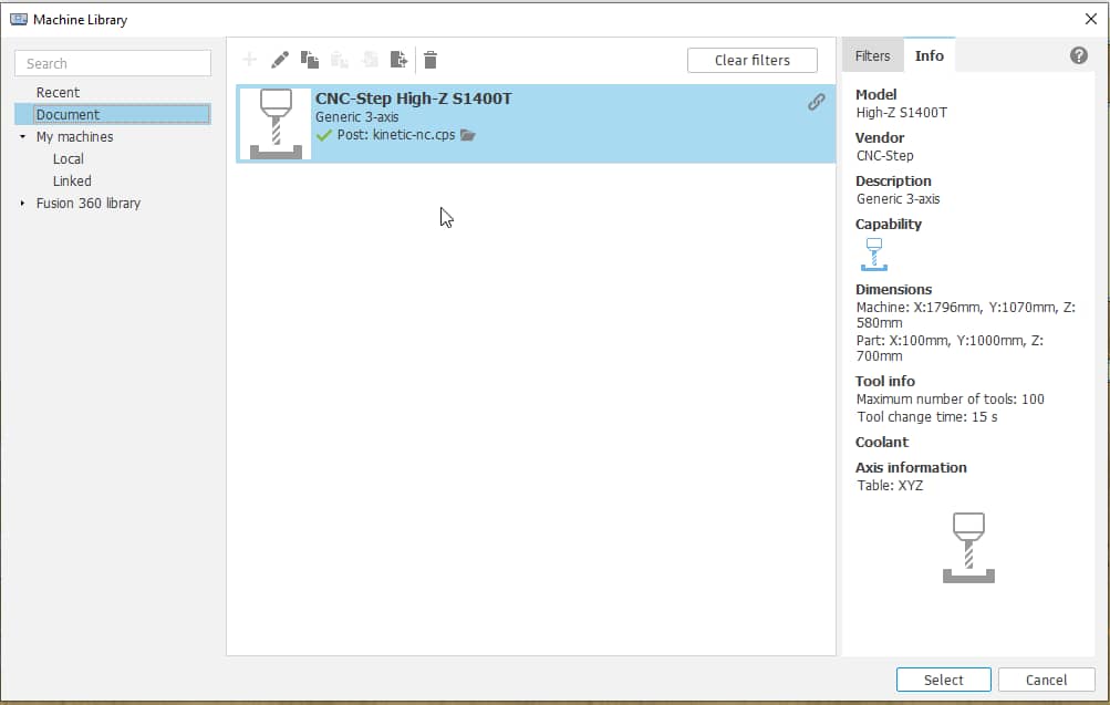
…with our CNC-Step High-Z S1400T and its Kinetic-NC post processor being selected as the machine:
I usually use a relatively sized stock in my CAM with material added to the sides only, when working with sheet material:
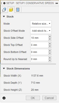
Here’s an overview of the stock with material added to the design’s bounding box sides and the choice of my zero for the coordinate system - the lower left, bottom stock corner:
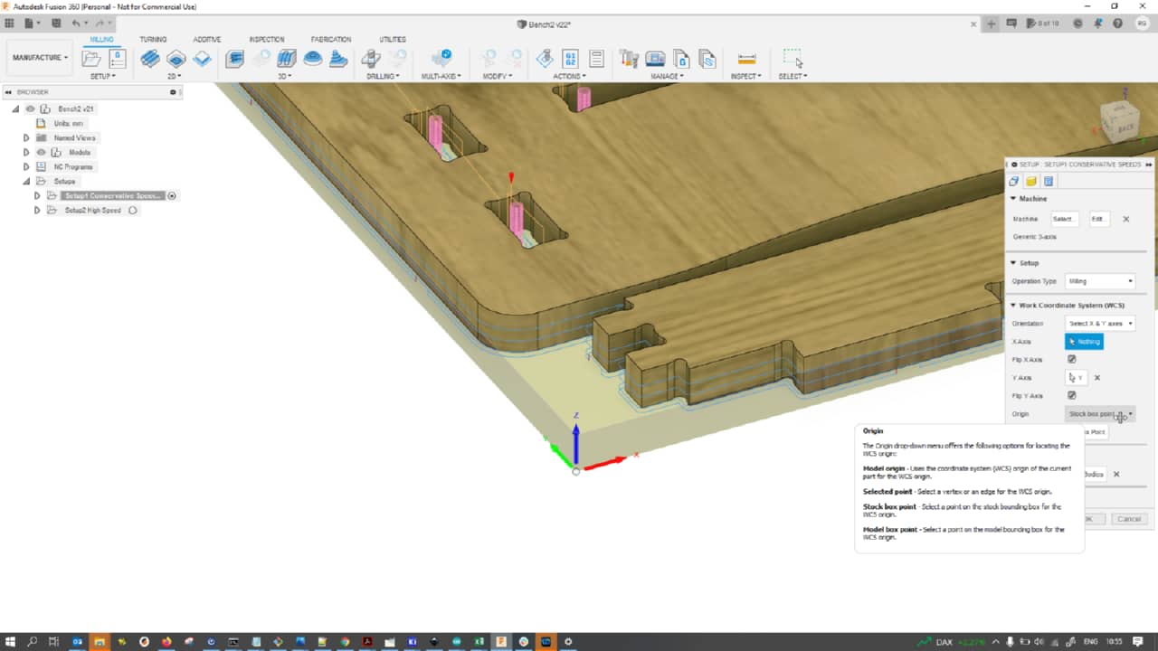
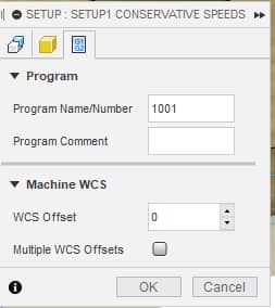
Lastly, for the WCS offset, I used 0, which means to use G54 coordinate system in our machine:
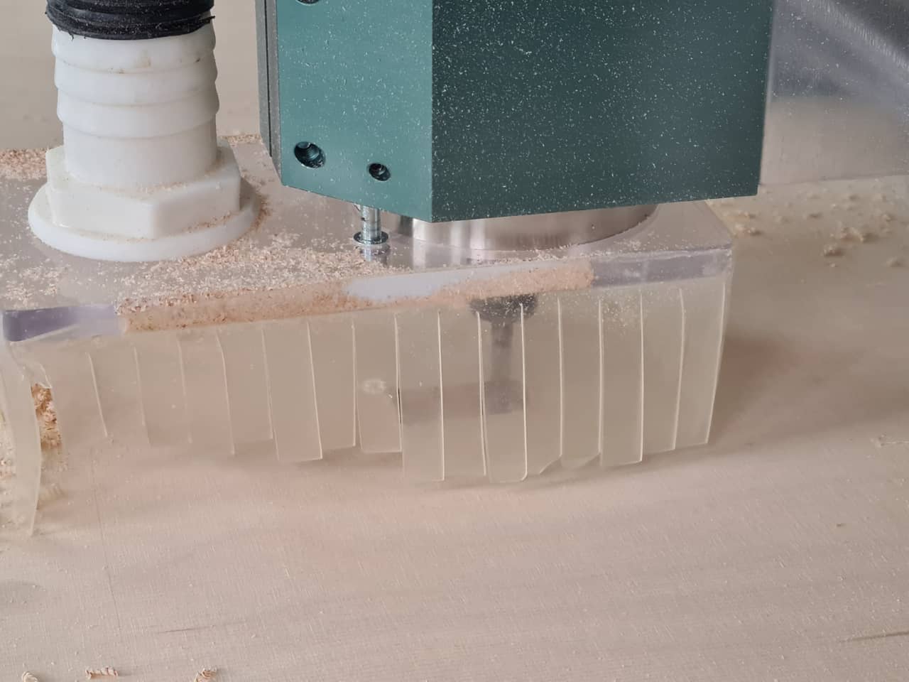
Milling on the CNC Machine
I then ran the post processor, took the resulting Gcode for my tool paths over to the CNC-Step High-Z S1400T and opened the NC-code in Kinetic-NC, the CNC machine’s control software. With my stock piece clamped on the bed in all 4 corners and the machine homed and zeroed on the surface of the underlay, I started the CAM job.
The first pocket cut went well, but I quickly realized that the feed and spindle speeds seemed to not be what I had set up in the CAM job. Turned out, the previous user had left some feed and spindle speed overrides in place in the control software that I failed to notice. Big fat warning and mental post-it: Always check the overrides on the machine before starting a job!:
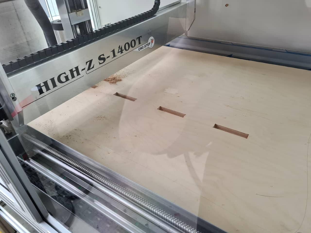
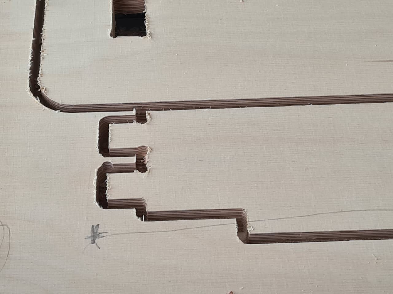
After not too long, all five bottom pockets were cut…
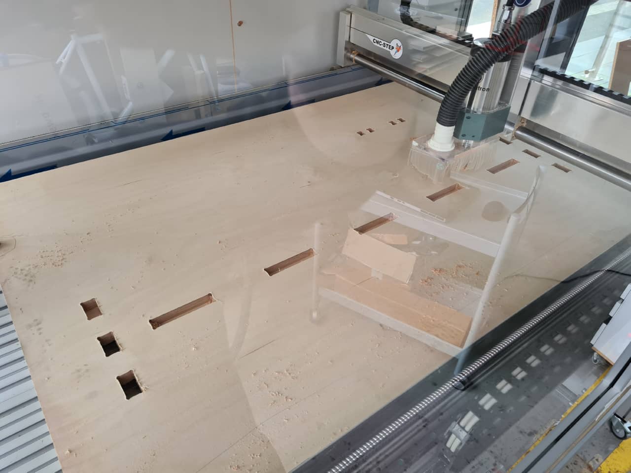
…and the machine went on to do the through holes. Note: some through holes appear darker that others because the sheet being used as a sacrificial underlay actually does have some holes in it - so there’s underlay material peeking through some holes and nothing underneath for others:
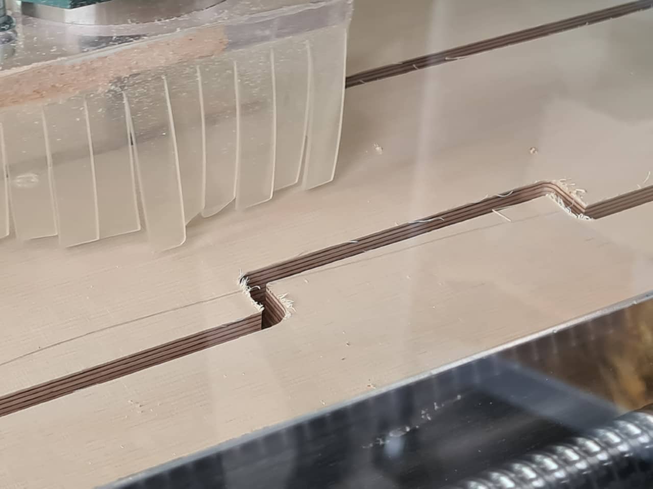
Here we can see the first contour cuts and the offending, missing dogbone corners - the inside corners are simply rounded because of the round mill bit, making assembly later nearly impossible. This could have been fixed with a chisel afterwards, too, but I did not want to do any more manual cleanup than necessary, so I fixed it by rerunning the contour cuts with dogbone corners again, as described previously:
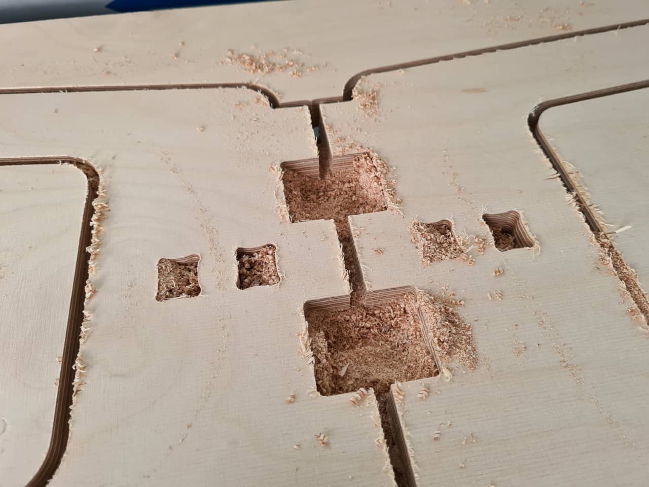
This left me with some good, internal corner holes (note that not all inner corners on this picture have rerun yet, the machine ist just starting out with the ones at the fingers):
On this picture, you can see the mishap with the dislodged parts of the cut. This can be dangerous, as parts can go flying, but also expensive, as tools can break when dislodged pieces get jammed. In our case, thankfully the machine has a complete housing, so pieces flying off would not be as dangerous as on an open machine. I also got lucky here with the pieces being dislodged, but not actually pulled out of the cavity they sit in:
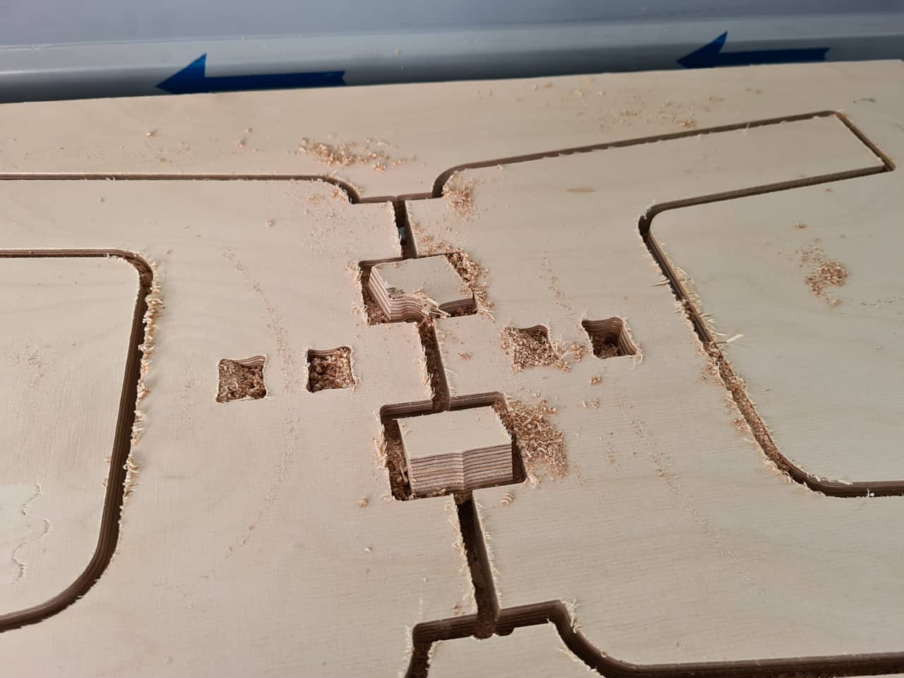
Here’s after removing the dislodged pieces:
So finally, after about 2 hours of cutting, fixing and recutting, my CAM job was finished. Here’s a nice shot of the sheet I used with all cuts finished still fixed inside…
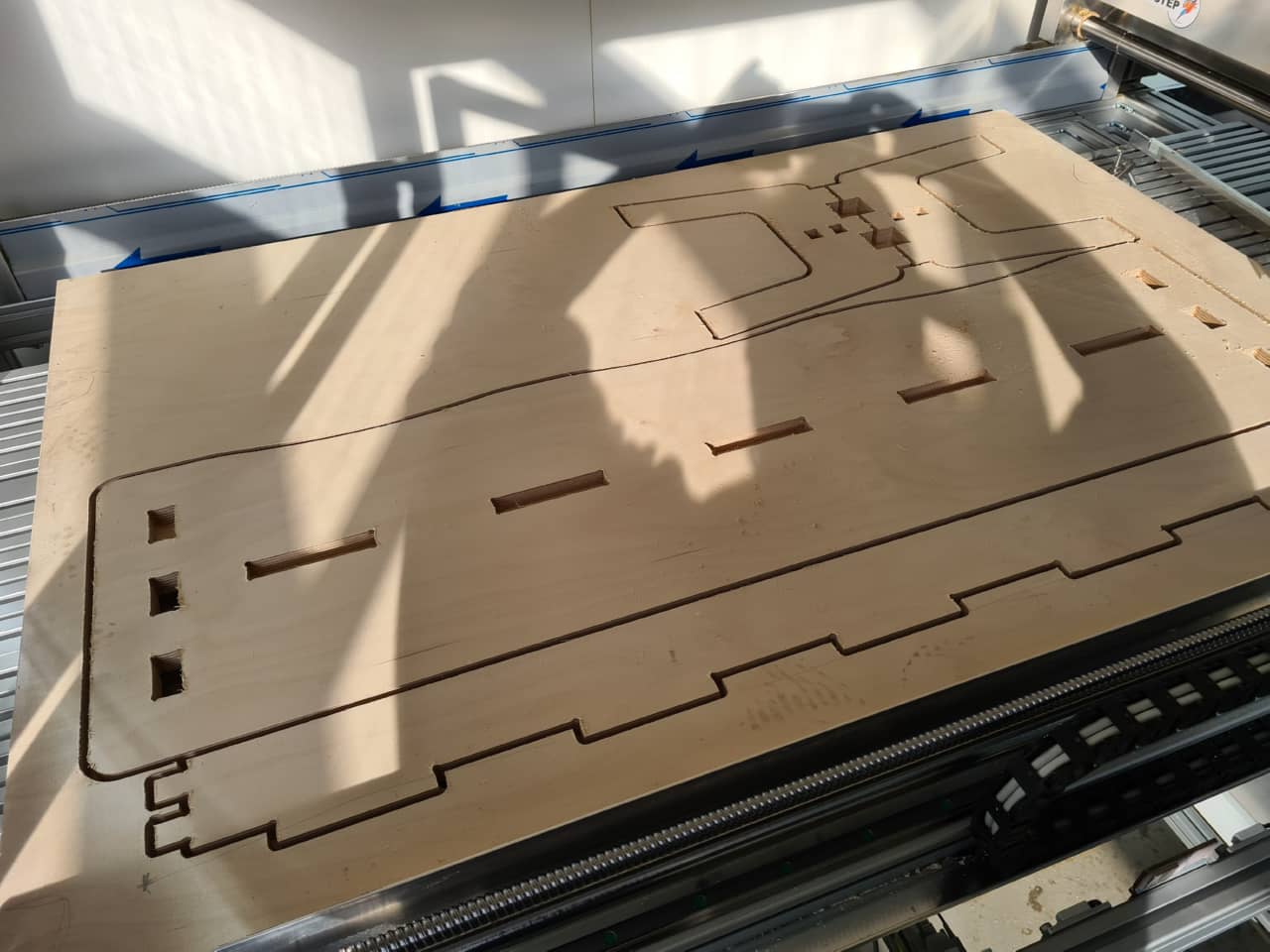
…and then outside of the machine:
Work Outside the Machine
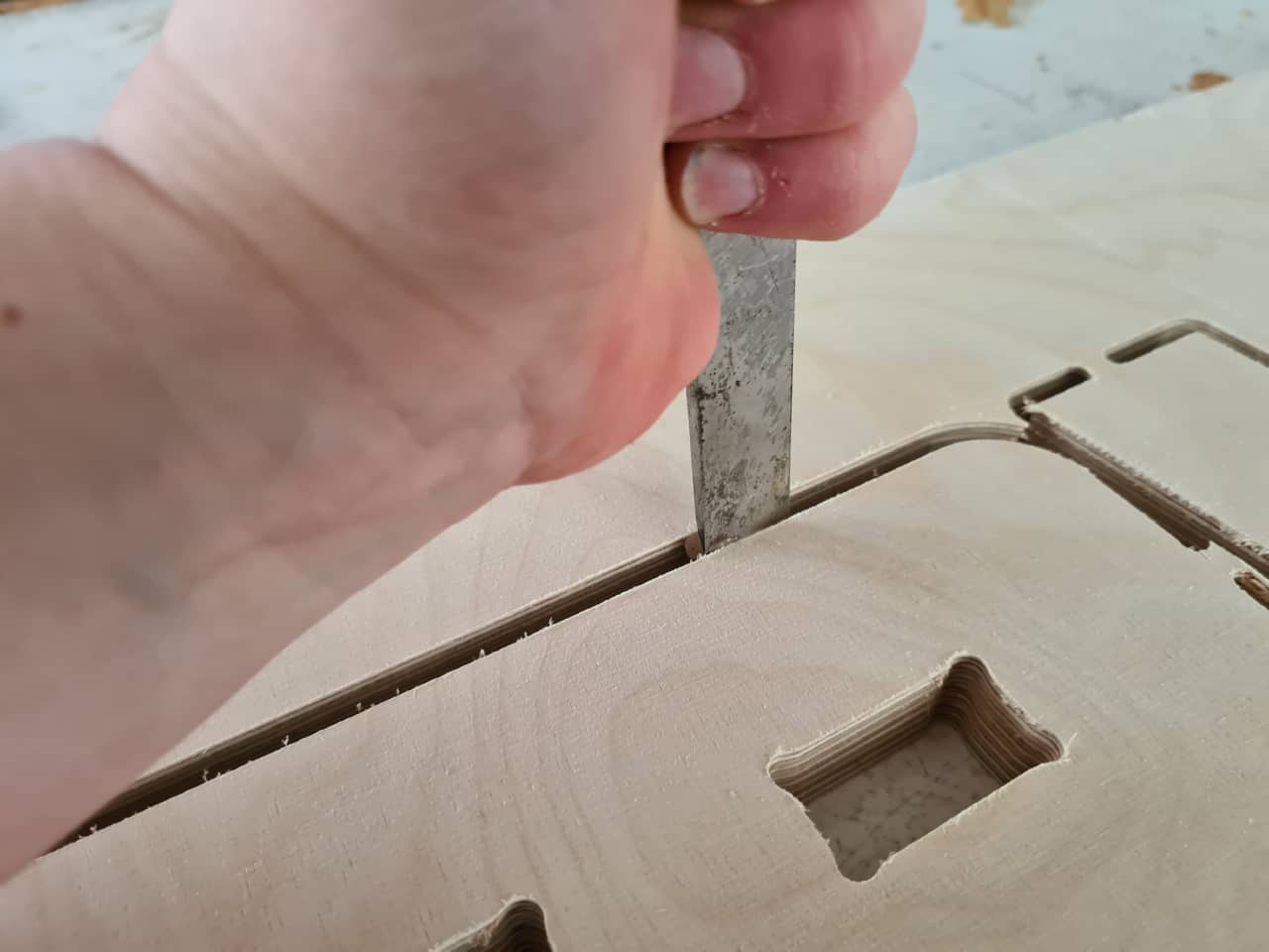
Using a straight chisel, I marked off the tabs and removed them by chiseling from the outside in (so the edges would not rip out):
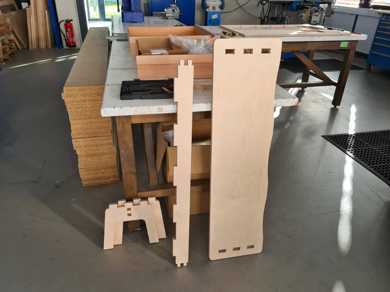
After cutting all pieces free, I gave all edges a quick sanding with 80 grit sandpaper to break the sharp edges and remove any fuzz that was still left on the cut edges:
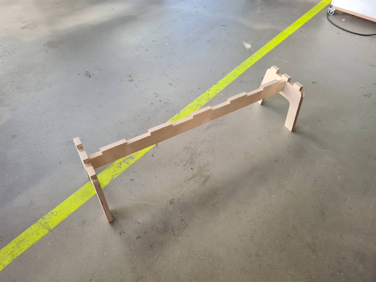
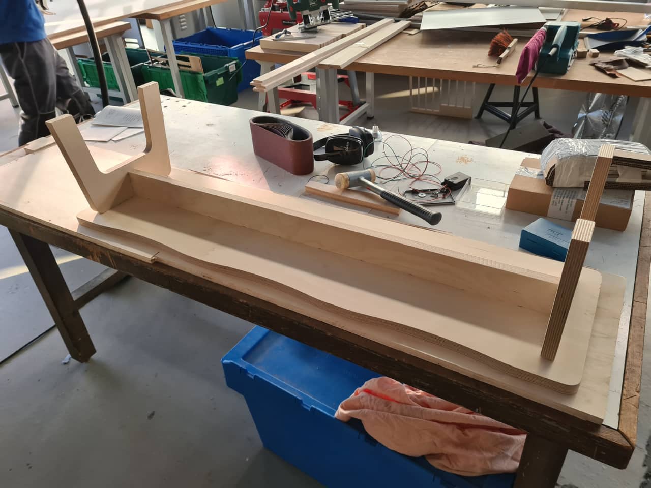
Then, it was time for assembly. I started by assembling the side pieces to the crossbar, using a deadblow mallet and a piece of multiplex wood in between the hammer and the hammered surface:
I then placed the seat part down, with pockets facing up, on a meticulously cleaned piece of wood. This was to provide a stable base for the following hammering without scratching the surface of the seat. Using the same deadblow mallet and wood piece combination, I hammered the sides-crossbar combo into the underside of the bench seat. This took quite some effort, but after getting the fingers started in their holes, they went in slowly with every blow. In the end, all the fingers had disappeared completely in the pockets:
Finished Piece
Here is , again, the final result on its back…
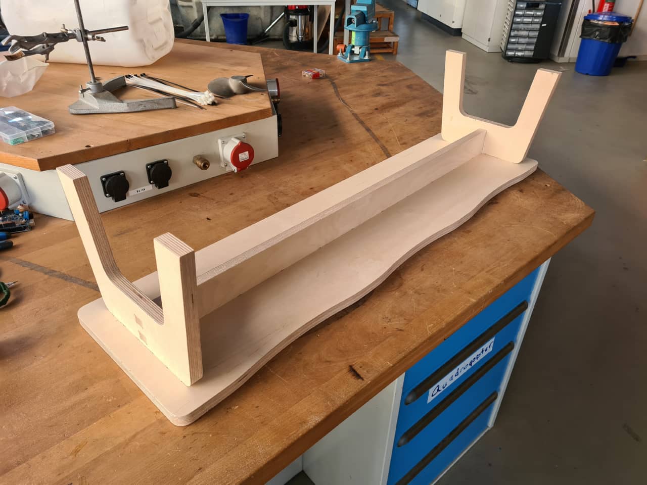
…and standing on its feet:
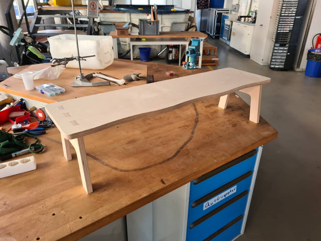
This is not a huge table - the bench is, in fact, only 26 cm high which seems to be a perfect sitting height for little humans:
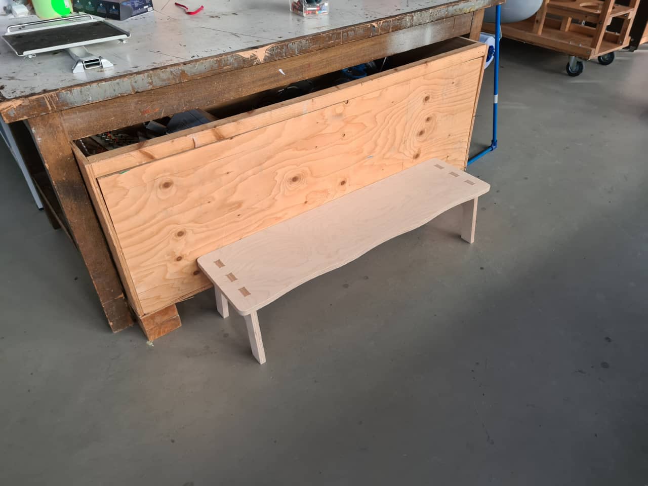
Change of scenery: I took the bench back to my house, where it didn’t actually end up in the niche I planned earlier, but on the opposite side. I was very happy with the result - the target group seemed to really like it, too :)
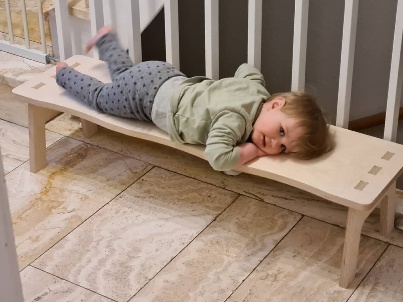
It even doubles as a little naptime hangout!
Design Files
- Kiddy Bench Fusion 360 model file and CNC layout: