Group Assignment
Division of Labor
For this assignment, Leen made the CAD model of a test piece, Aaron made the CAM and cut the part on the large format CNC machine, and Roland made the analysis of the finished part.
Creating the CAD Model
Basic Idea
Creating the Part
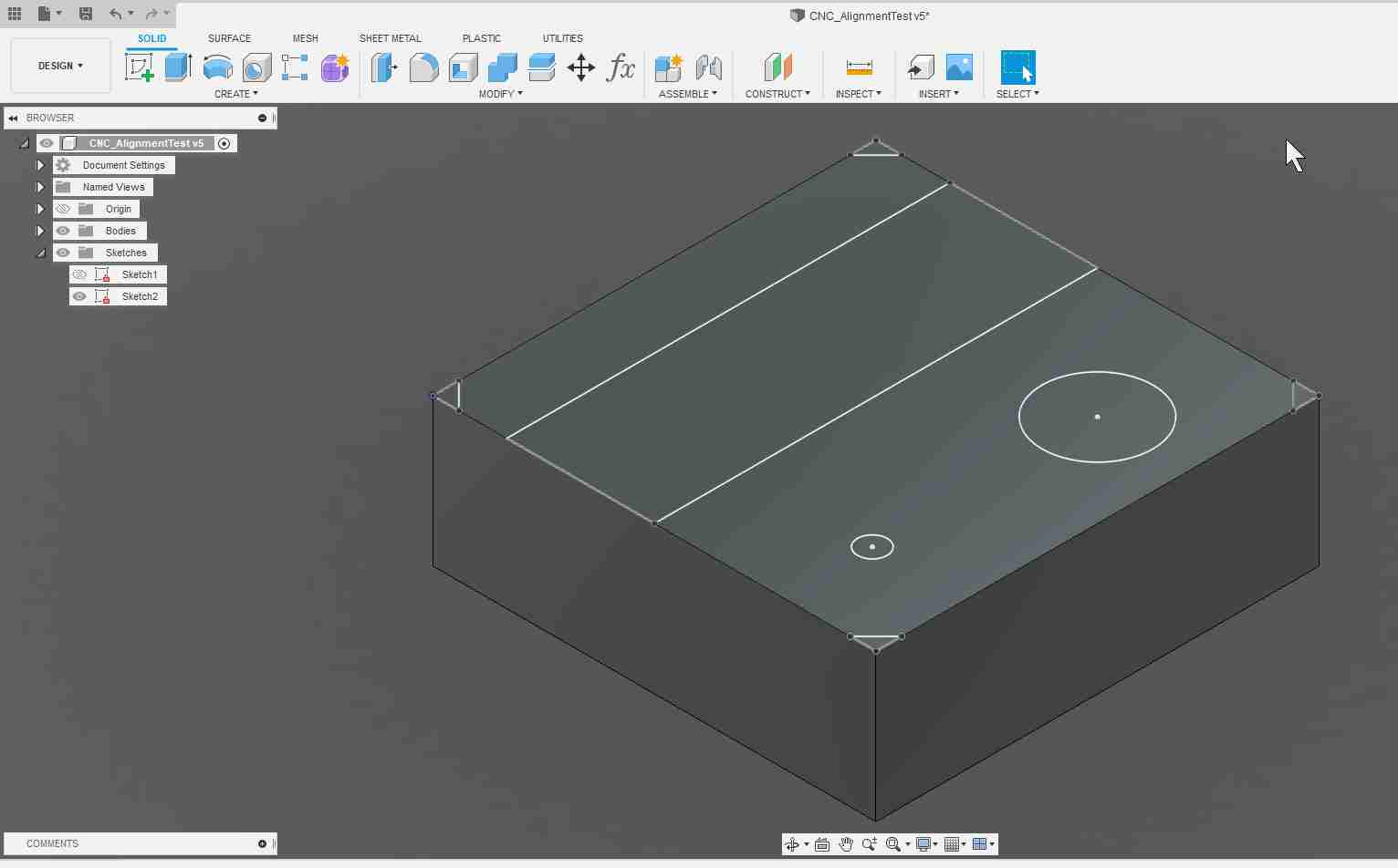
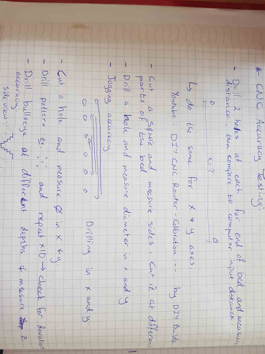
Parameters for Testing
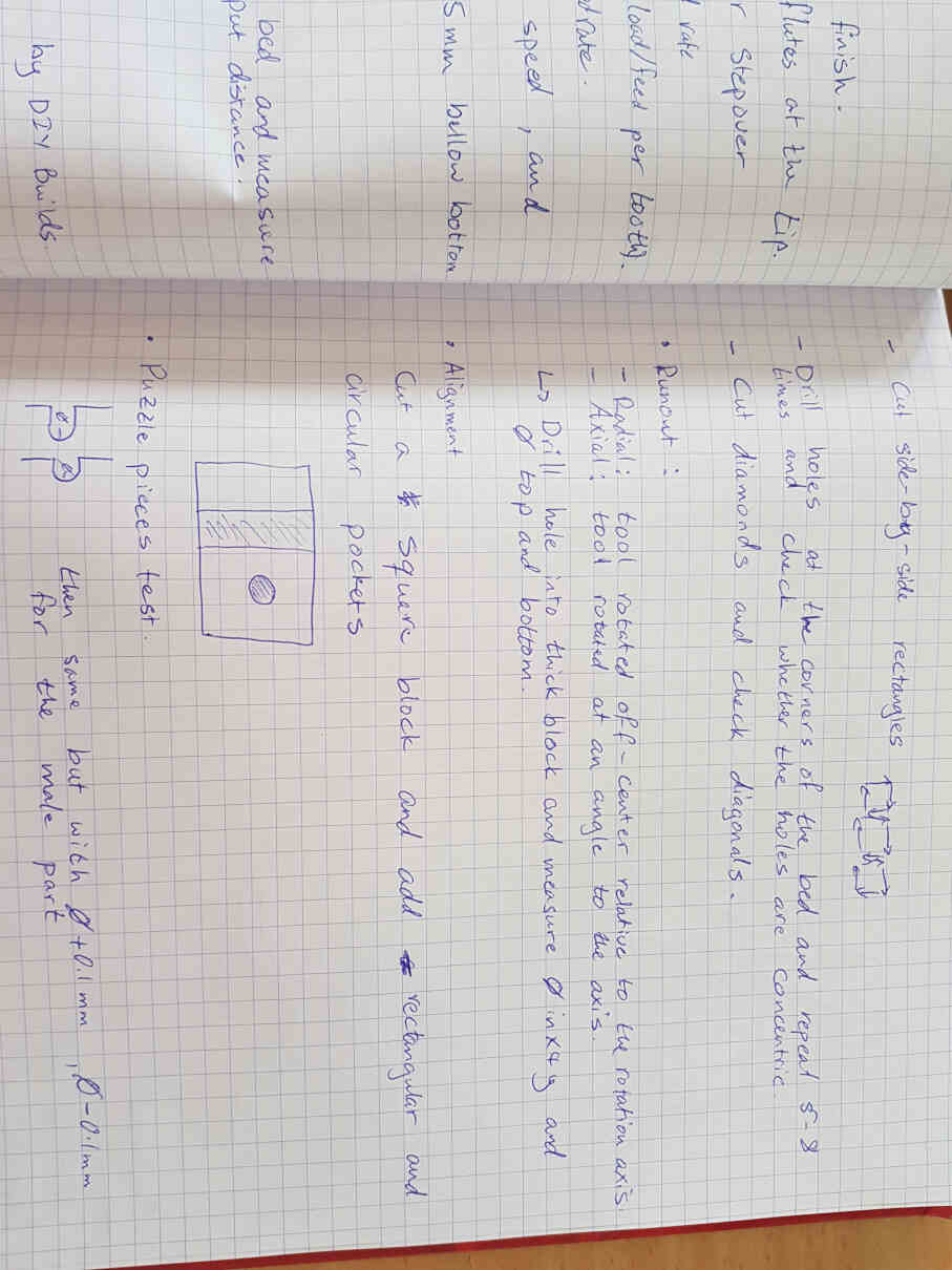
Parametric Design
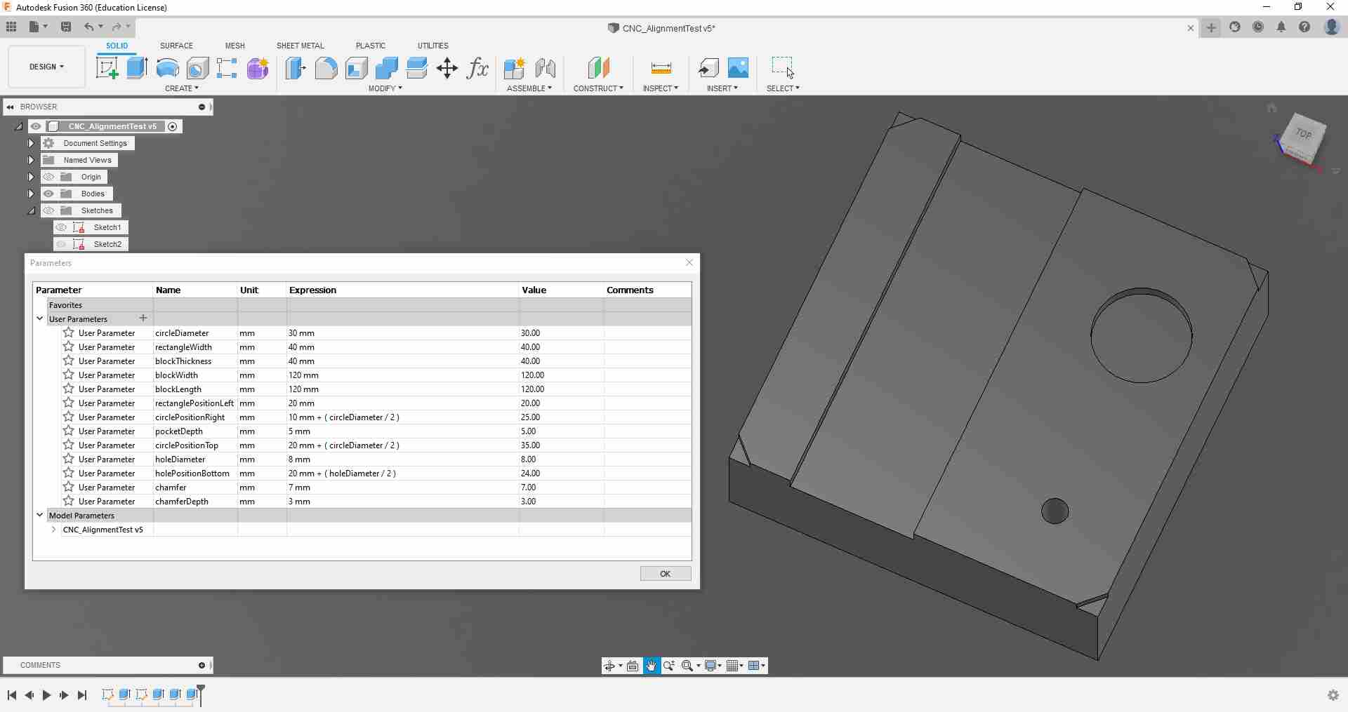
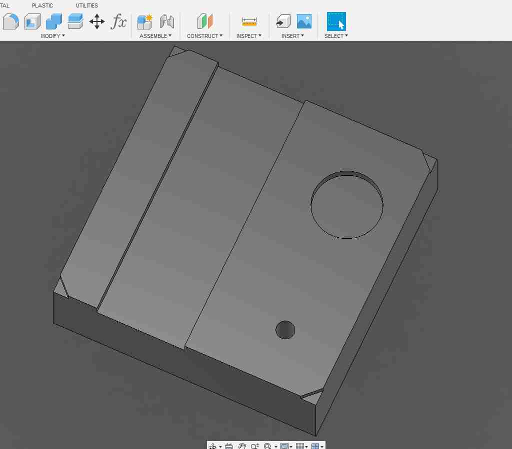
Final Result
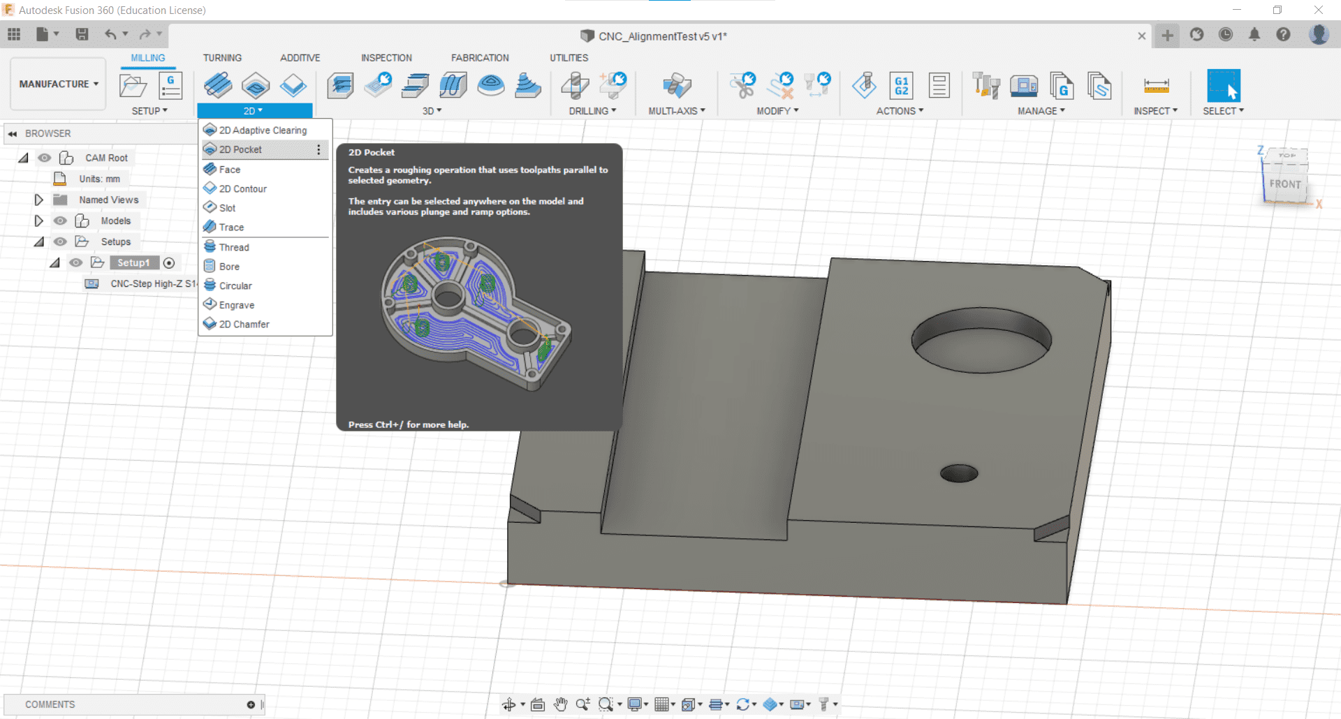
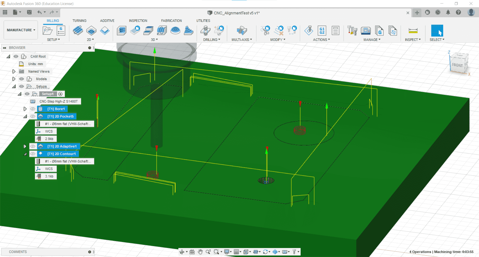
Creating the CAM
Getting Started
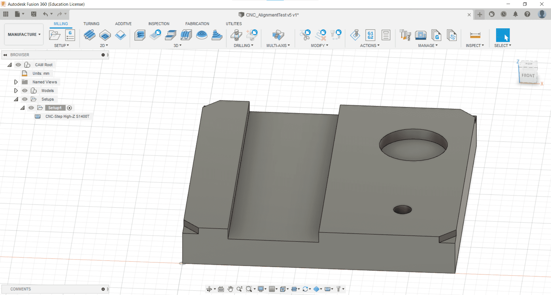
After importing the post processing, and machine libraries, and adding a couple of our tools to the tool library in the Manage tab of the Manufacture toolbar, I was ready to begin the CAM. I started by importing the test part that Leen had made the day before.
New Setup
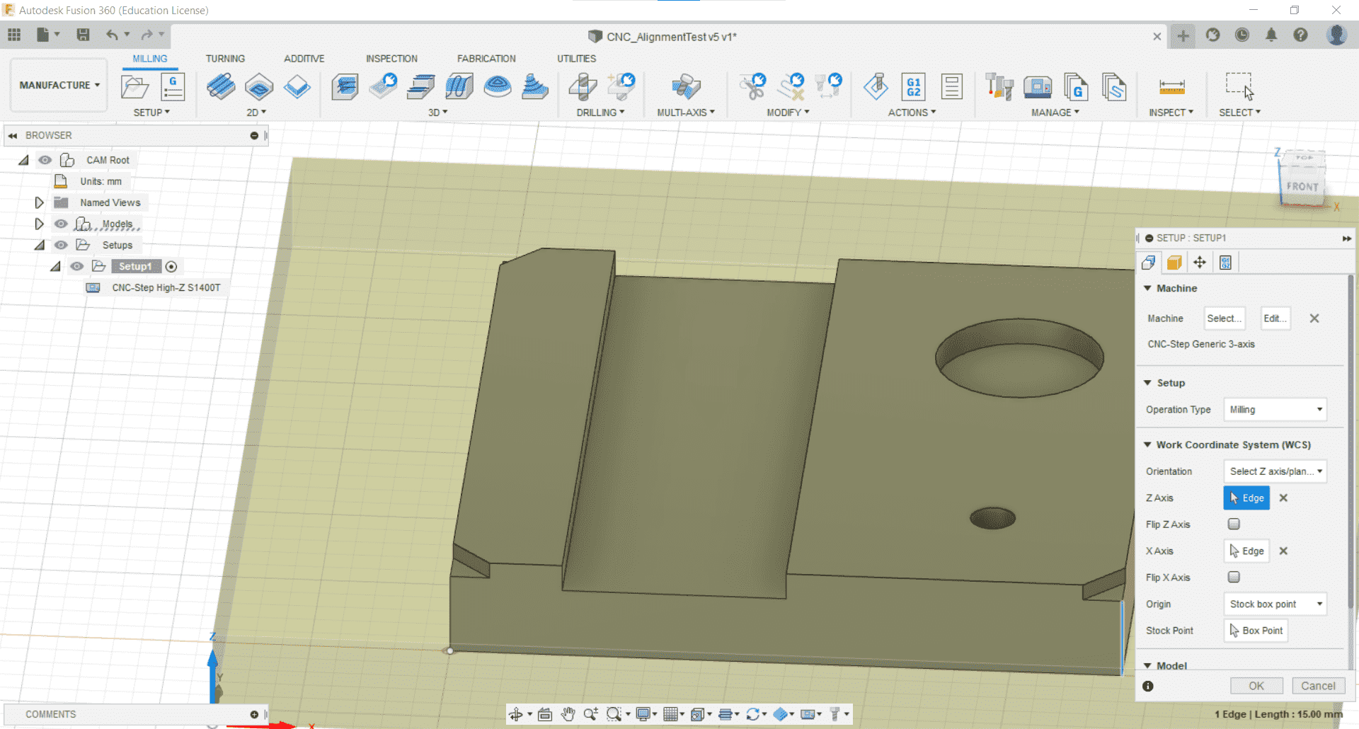
I created a new setup for milling and I placed the origin on the lower left corner and the bottom of the stock.
Stock
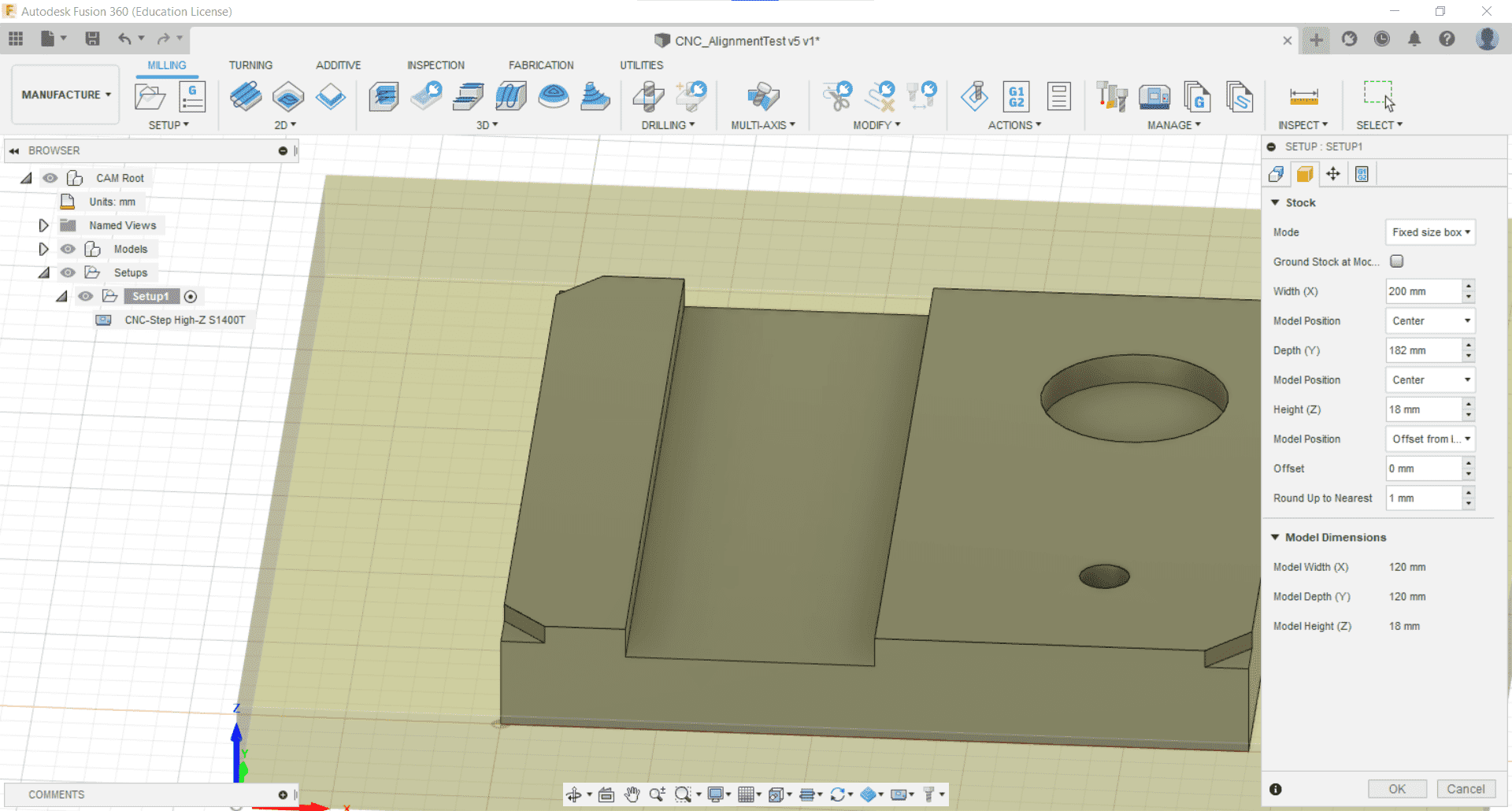
We had some scrap wood in the lab that would be suitable both for the workpiece and for the sacrificial layer beneath so I set the dimensions of the stock accordingly and aligned the part to the center.
Fixtures
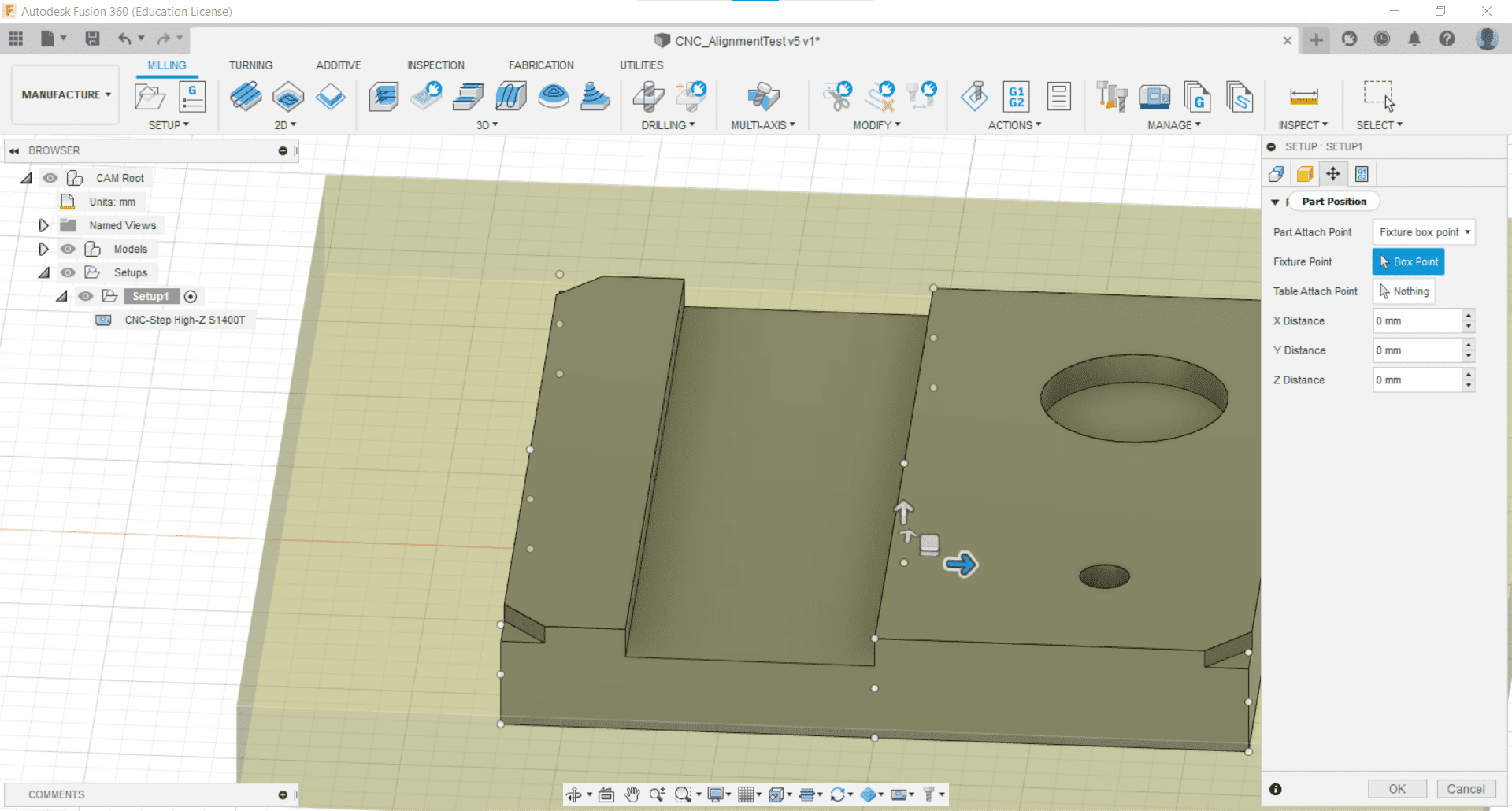
I decided not to model the fixtures and to just screw down the workpiece where I knew there would be no cutting.
Processing Setup

I also kept the post processing tab at its default values.
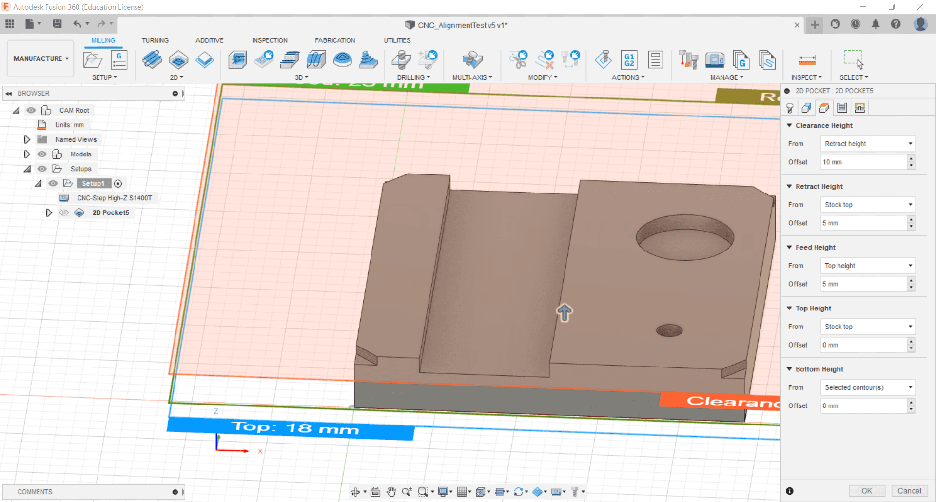
Bore
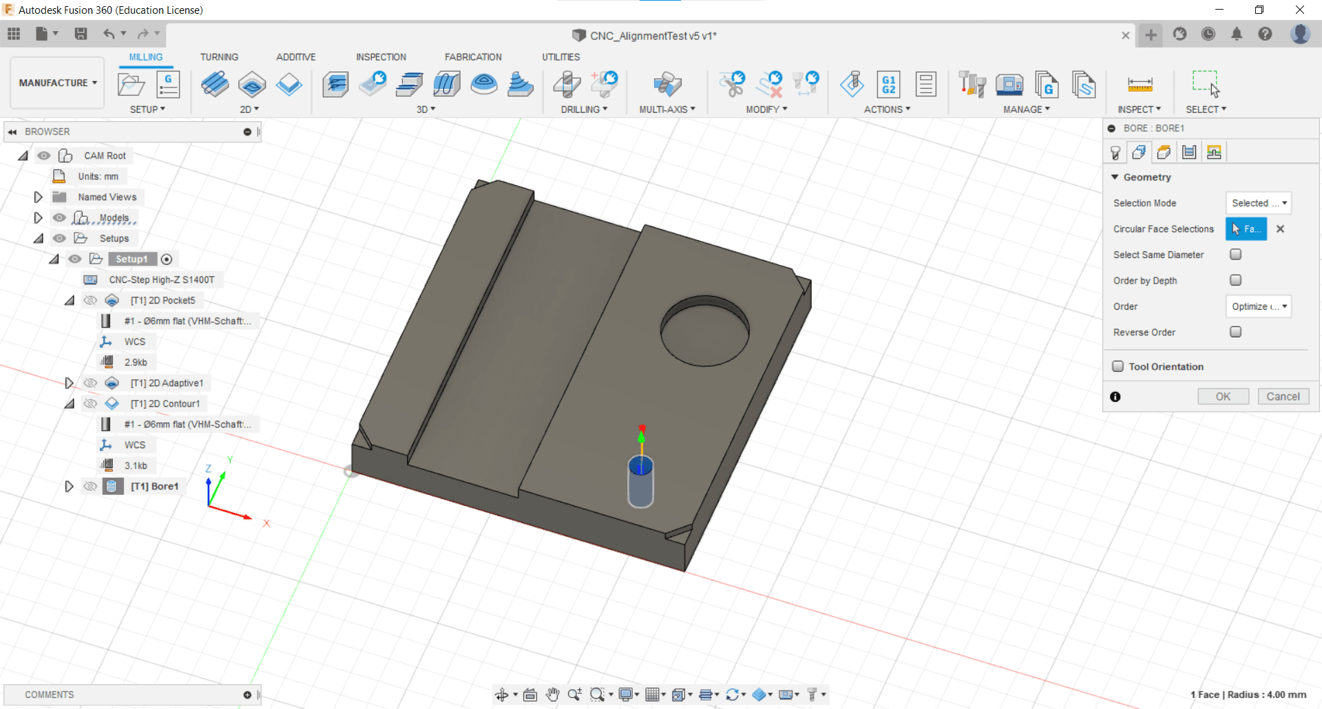
To mill the hole, I used the Bore tool in the 2D Milling tab. I selected the bottom of the hole.
Retraction Height
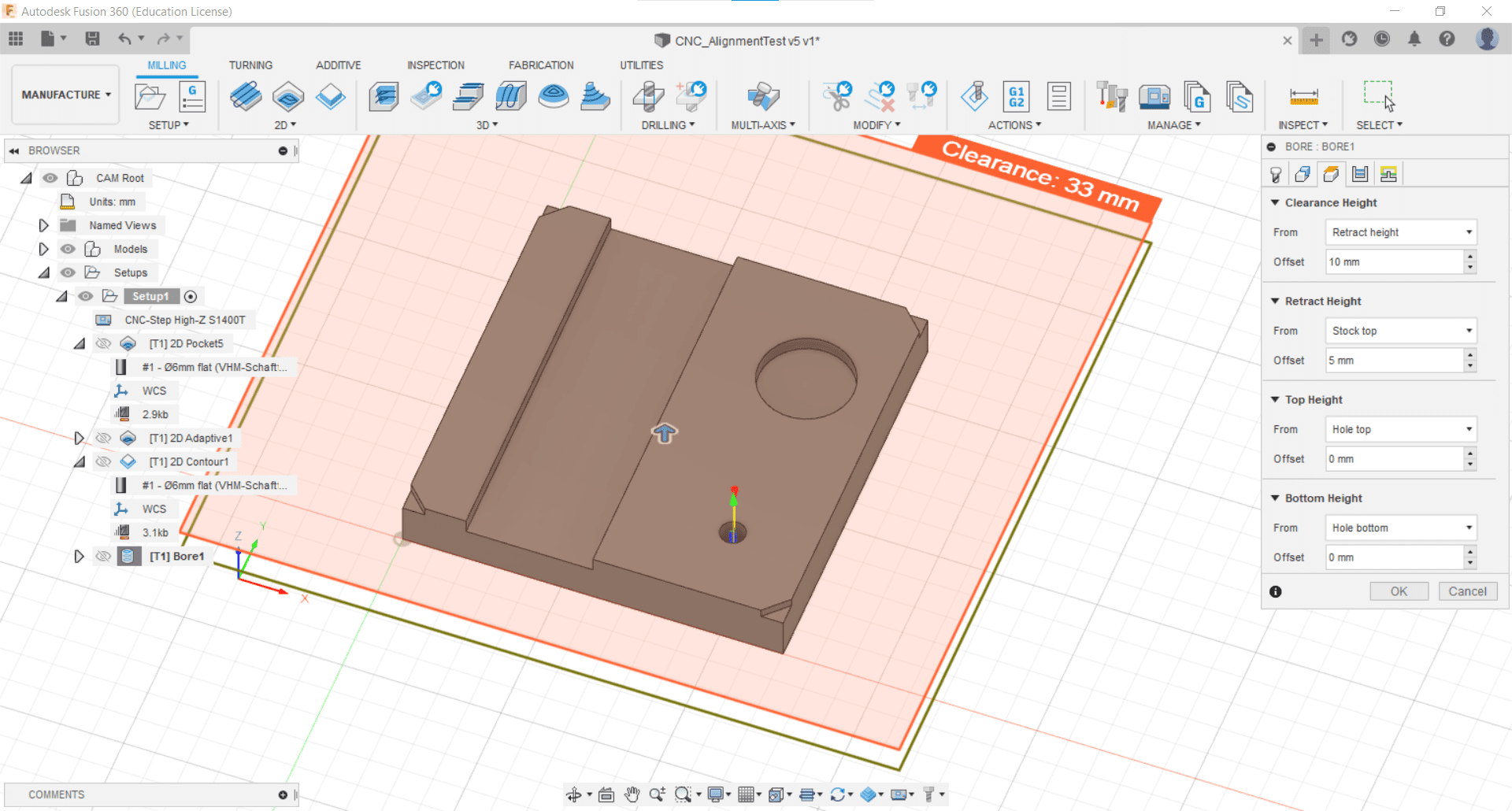
I kept the retraction heights at their default values.
Stock to Leave
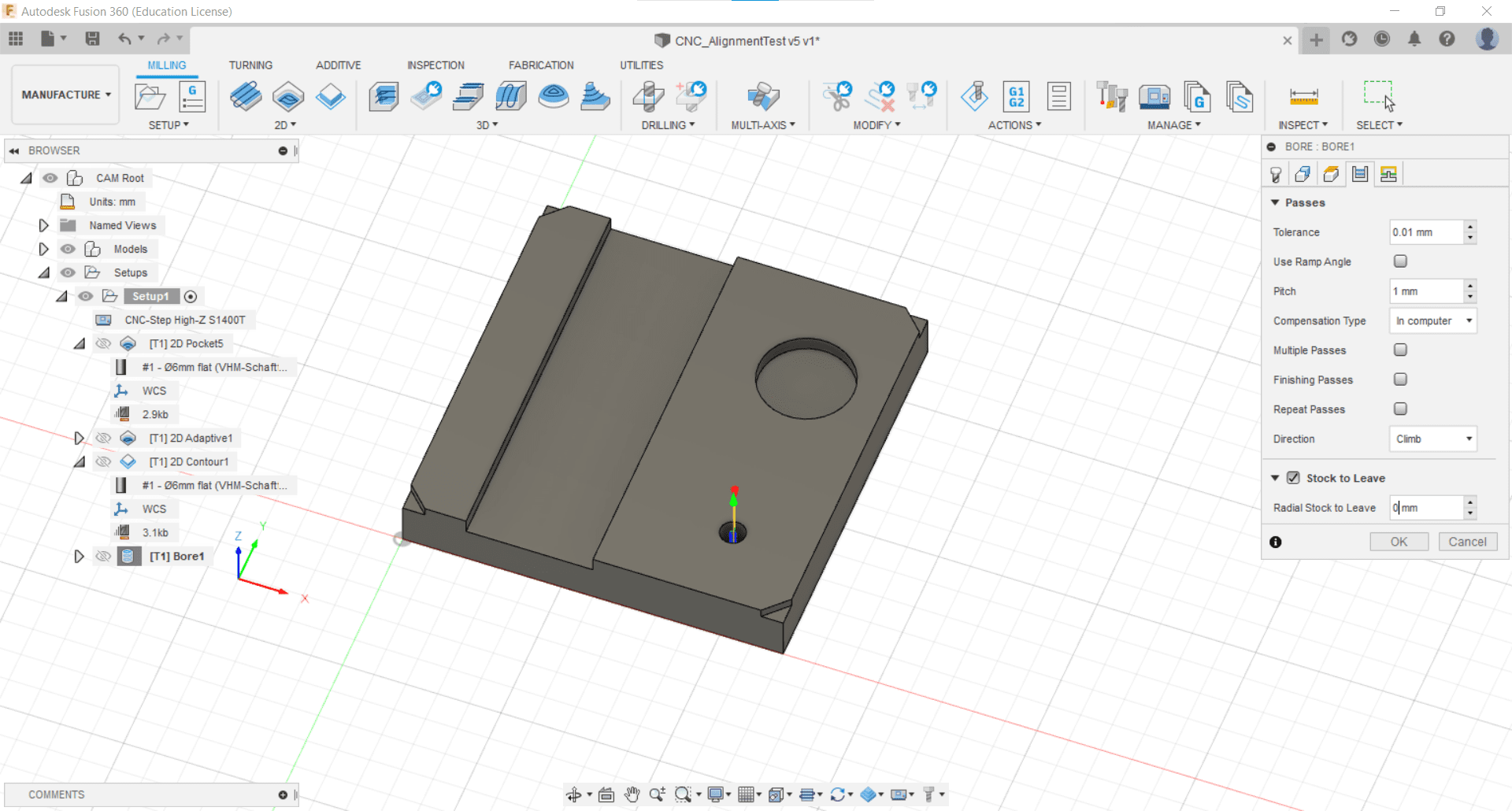
Since I didn't use multiple passes or finishing passes, I chose not to leave any stock in the radial or axial directions.
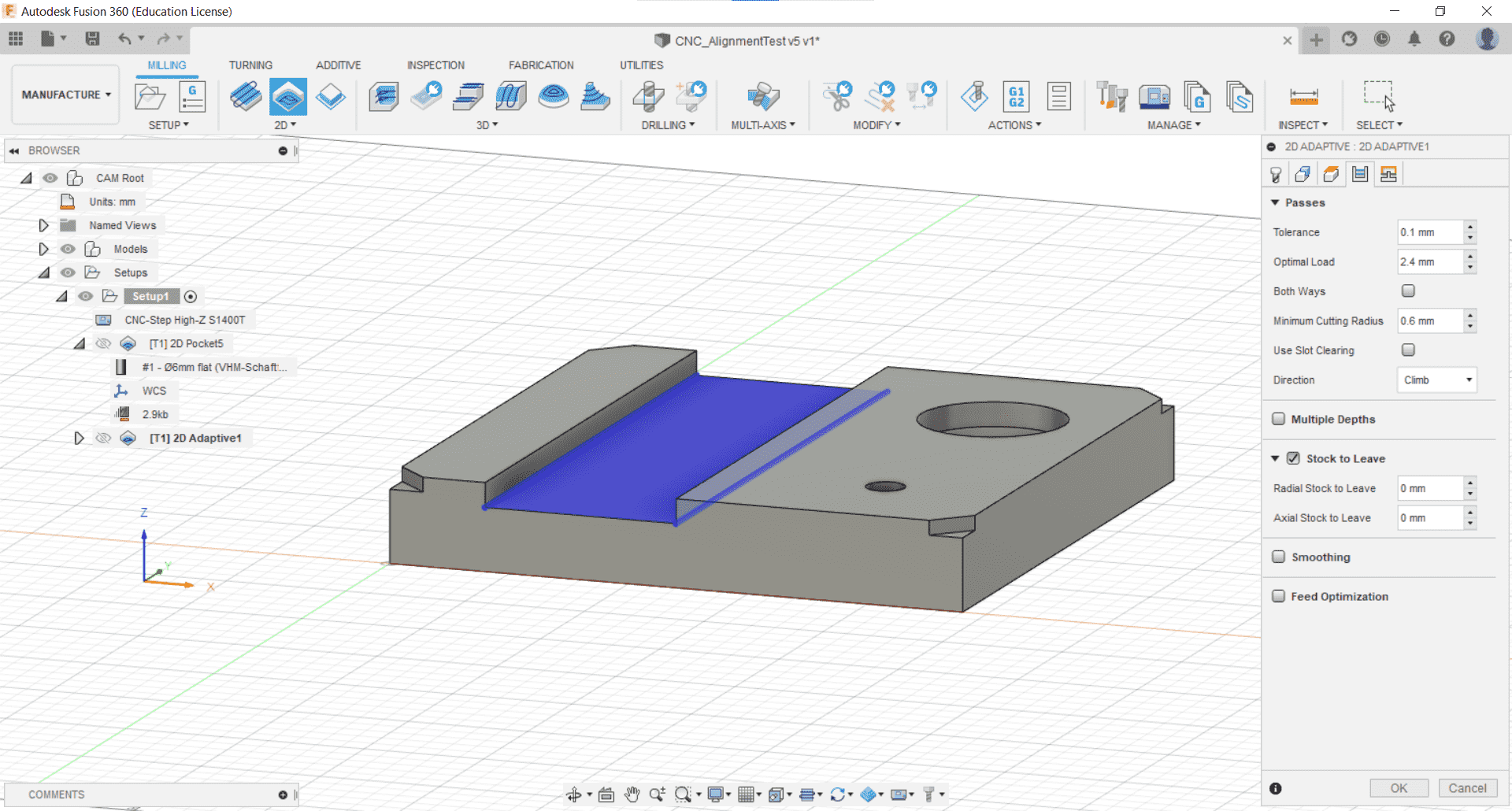
For the pocket, I decided to use the Pocket tool.
Tool
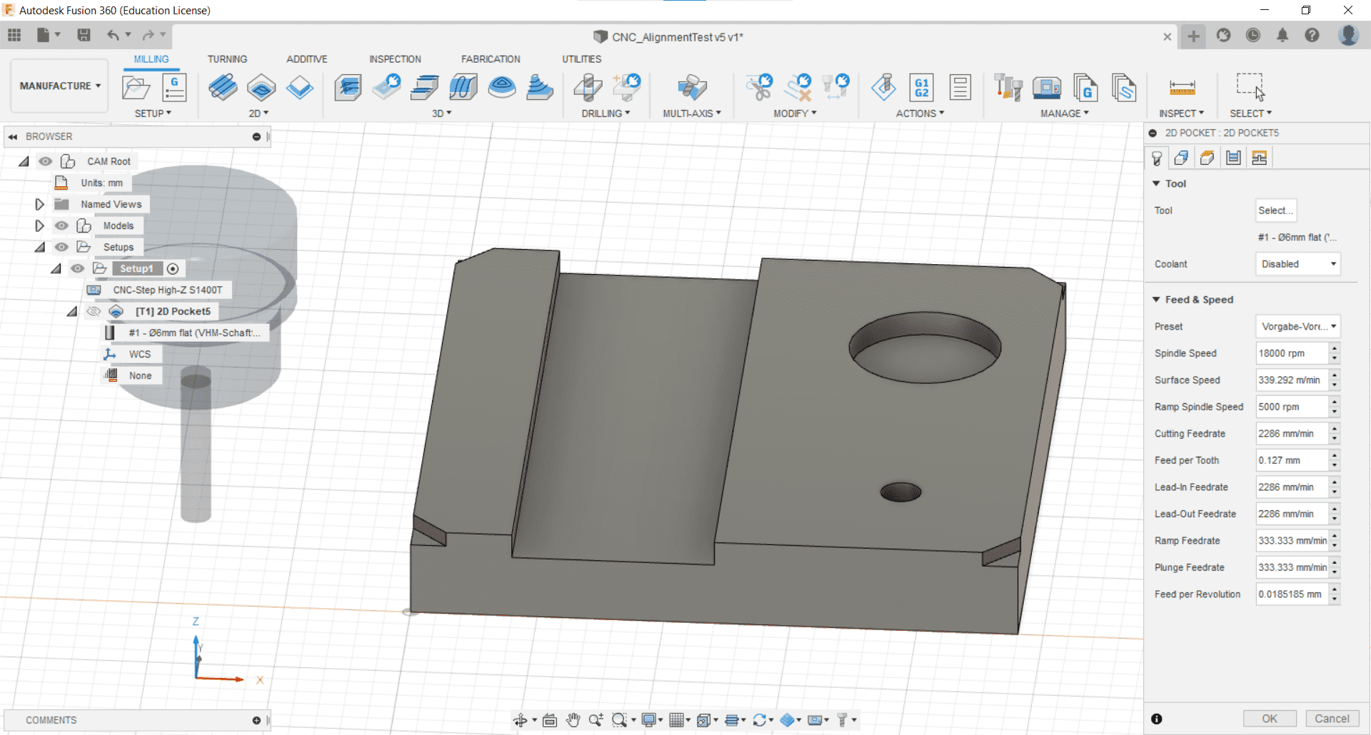
I selected the cutting tool to use,
Geometry
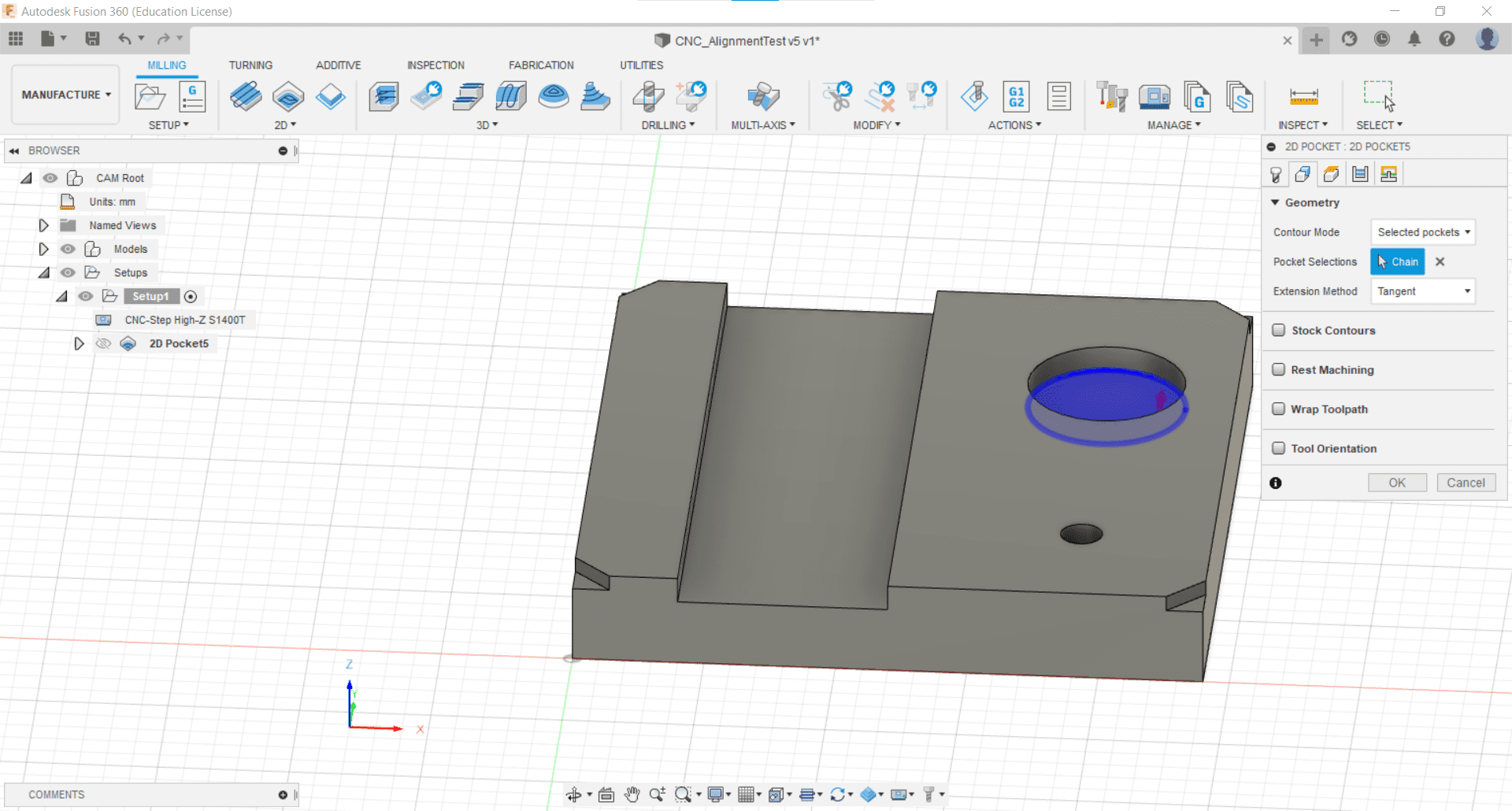
the geometry of the pocket to be cut,
Retraction Height
and once again kept the Retraction Height parameters all set to their default values.
Stock to Leave
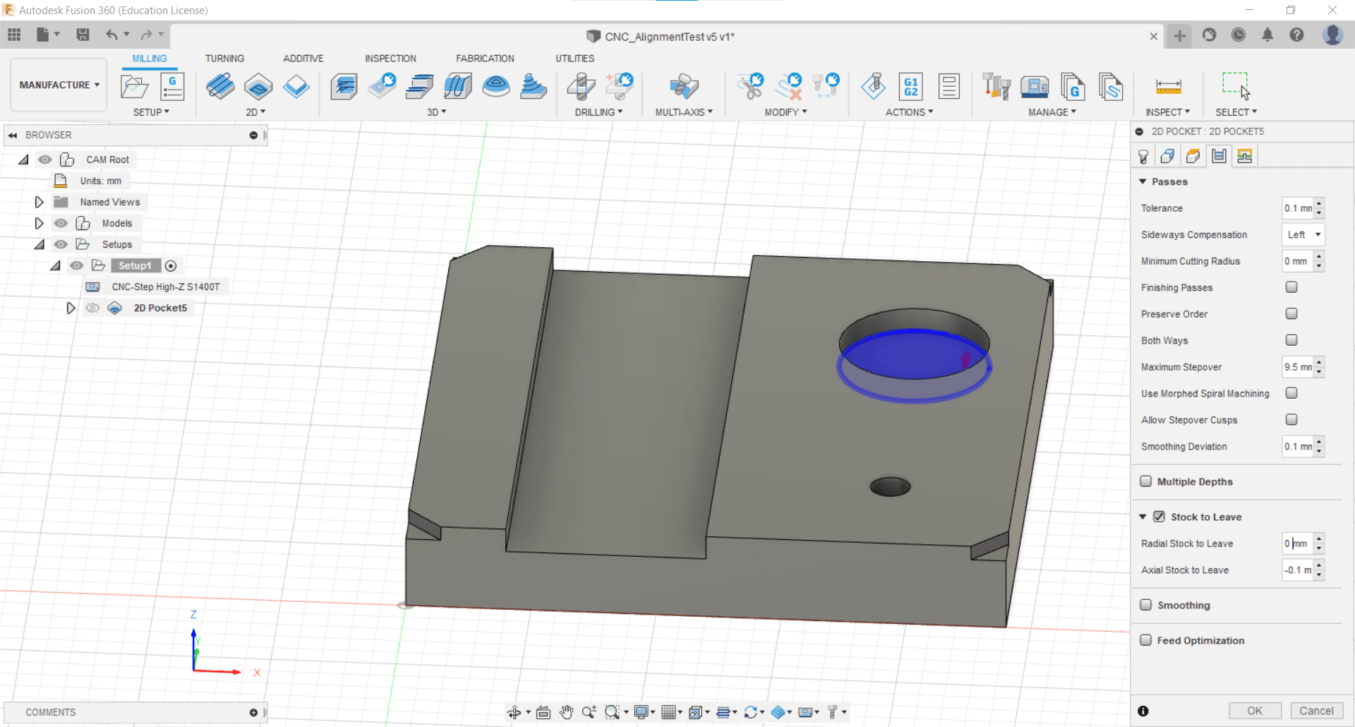
Since this was a test piece, I decided not to use multiple passes once again. The idea being, that we would see what the default parameters look like and then make adjustments from there. Since there were no finishing passes, I chose not to leave any stock.
Linking
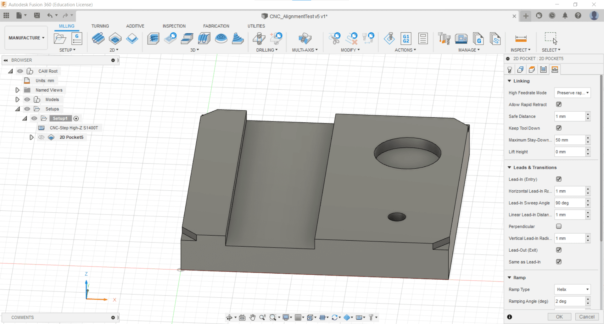
I also did not change any of the linking parameters.
Adaptive Clear
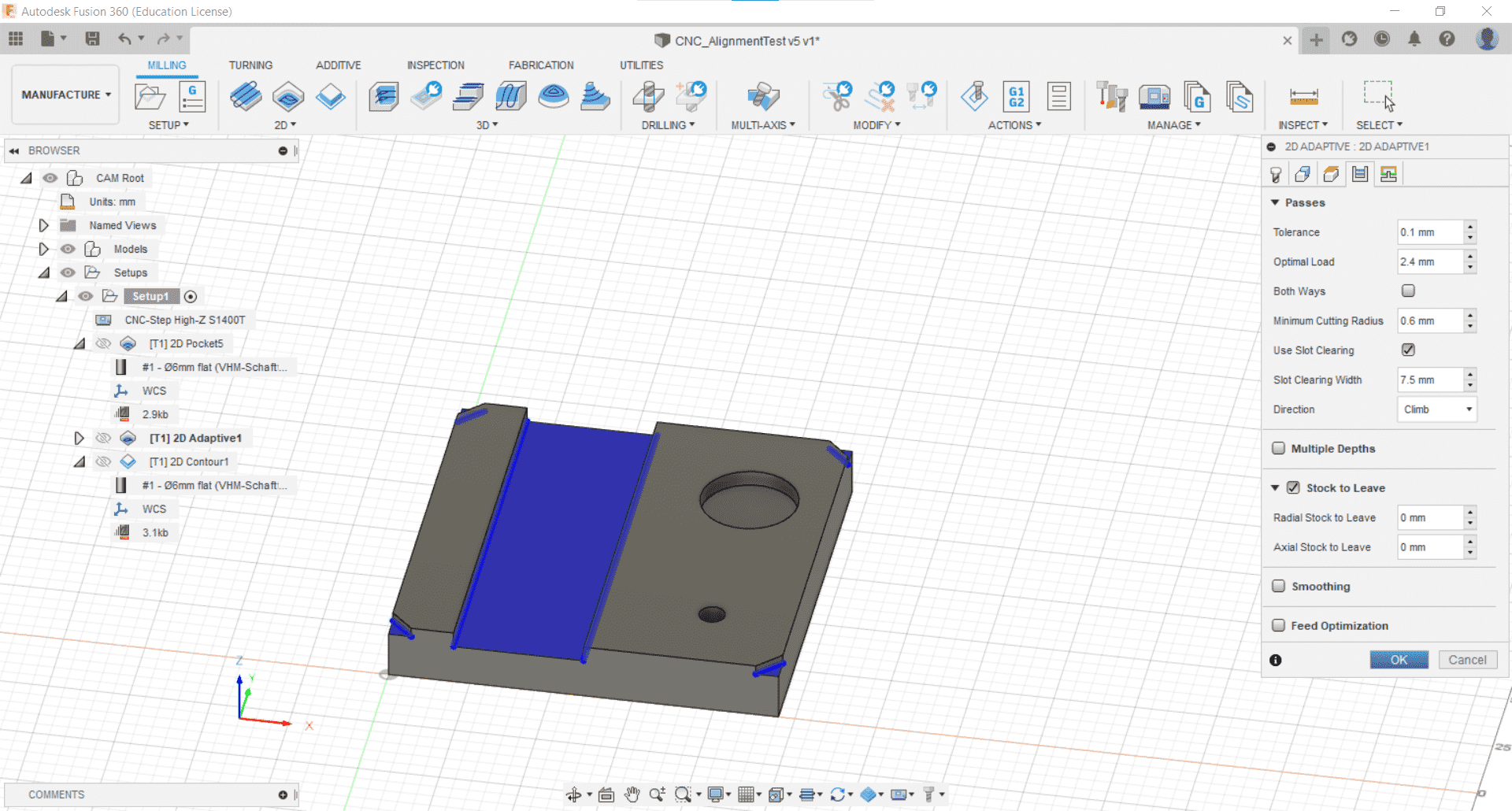
For the other features, I decided to use the Adaptive Clearing operation. I think I could have done these with the pocket operation as well, but I wanted to see the difference.
Parameters
I kept the parameters at their defaults once more.
2D Contour
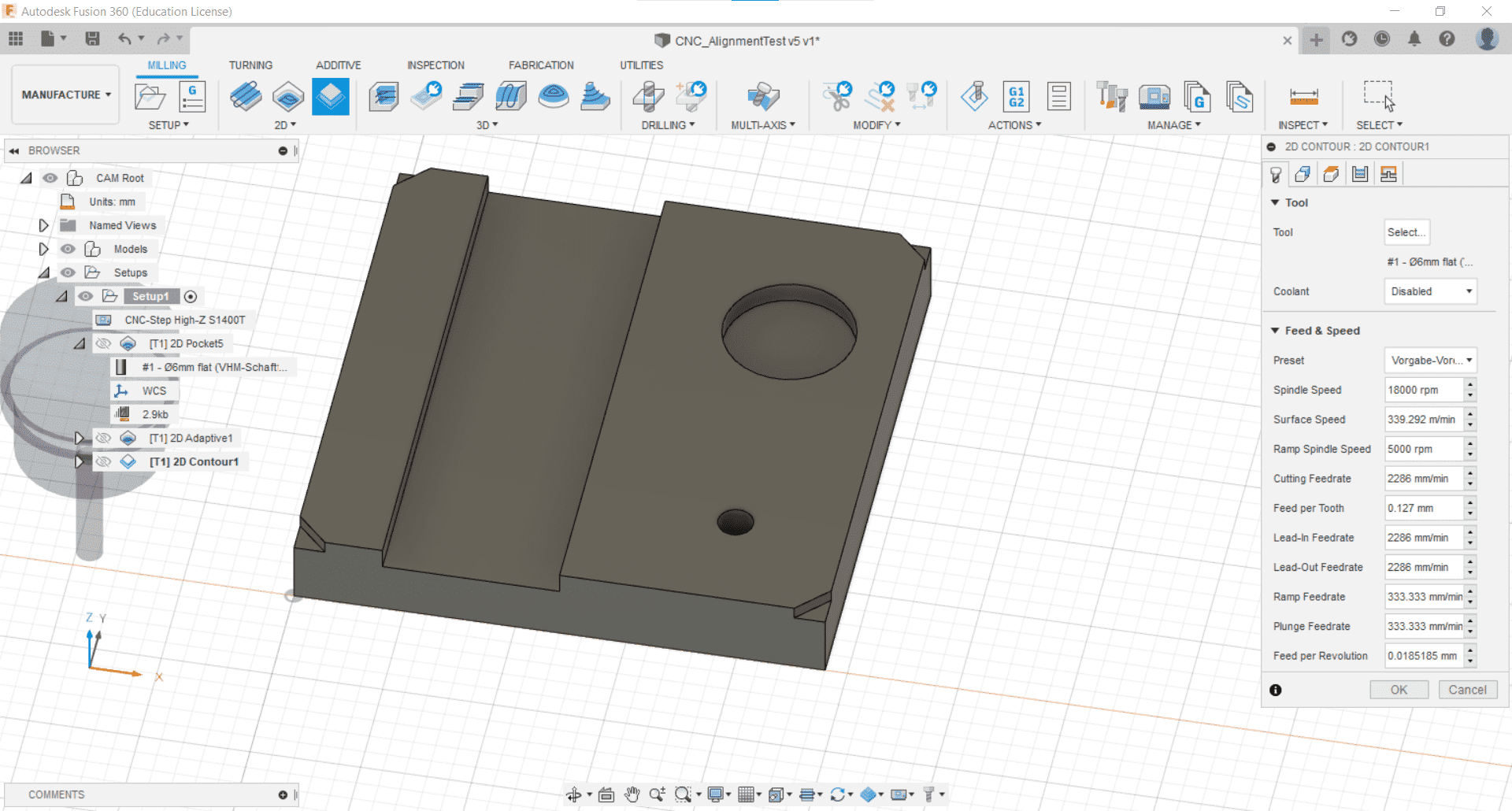
Finally, it was time to deal with the cutout so I selected the Contour Cut tool from the 2D Milling tab.
Tools and Geometry
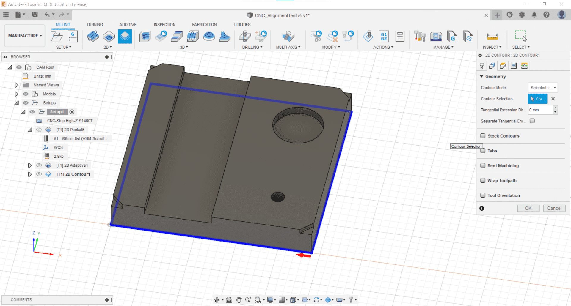
And then selected the contour I wanted to cut after choosing my cutting tool yet again.
Multiple Passes
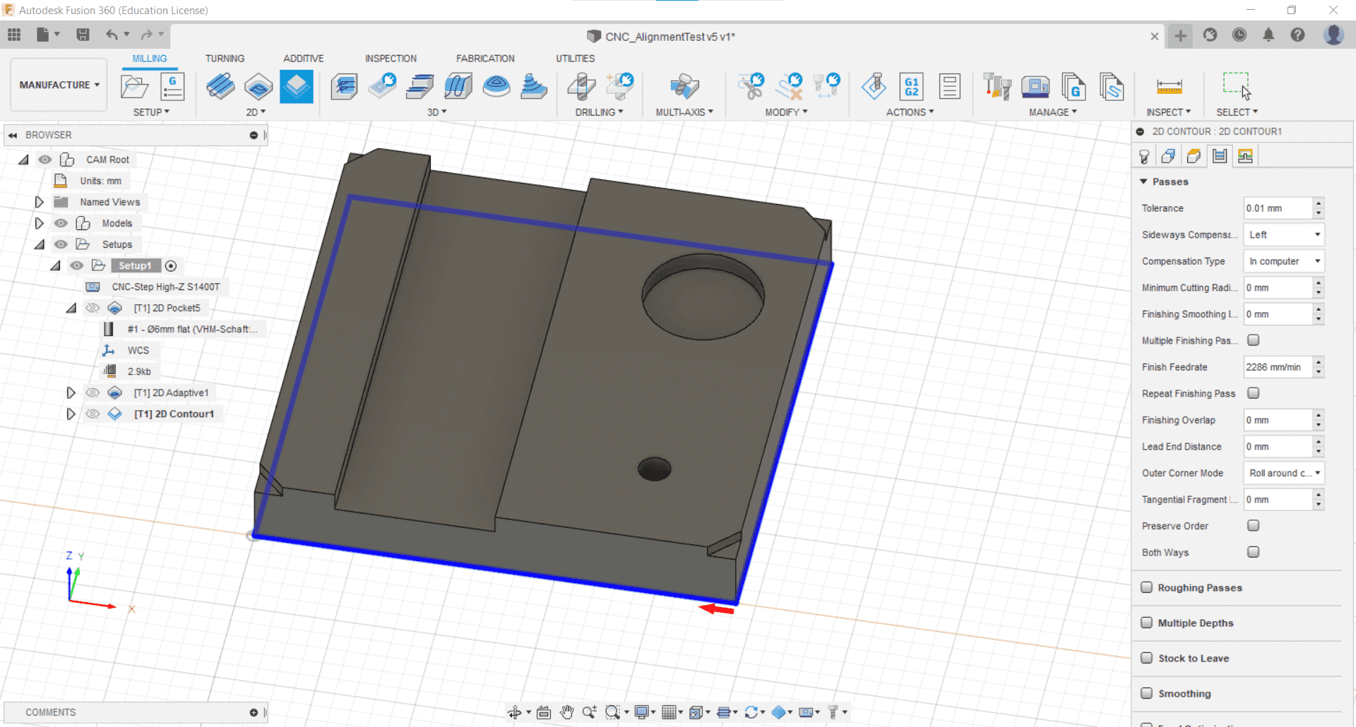
I kept most of the parameters at their defaults, but this time I used multiple passes so I changed the roughing stepdown depth to 5.1 mm.
Simulate
Then, in the Actions tab, I used the Simulate tool to visualize the tool-paths and make sure that everything was doing what I expected it to.
Tabs
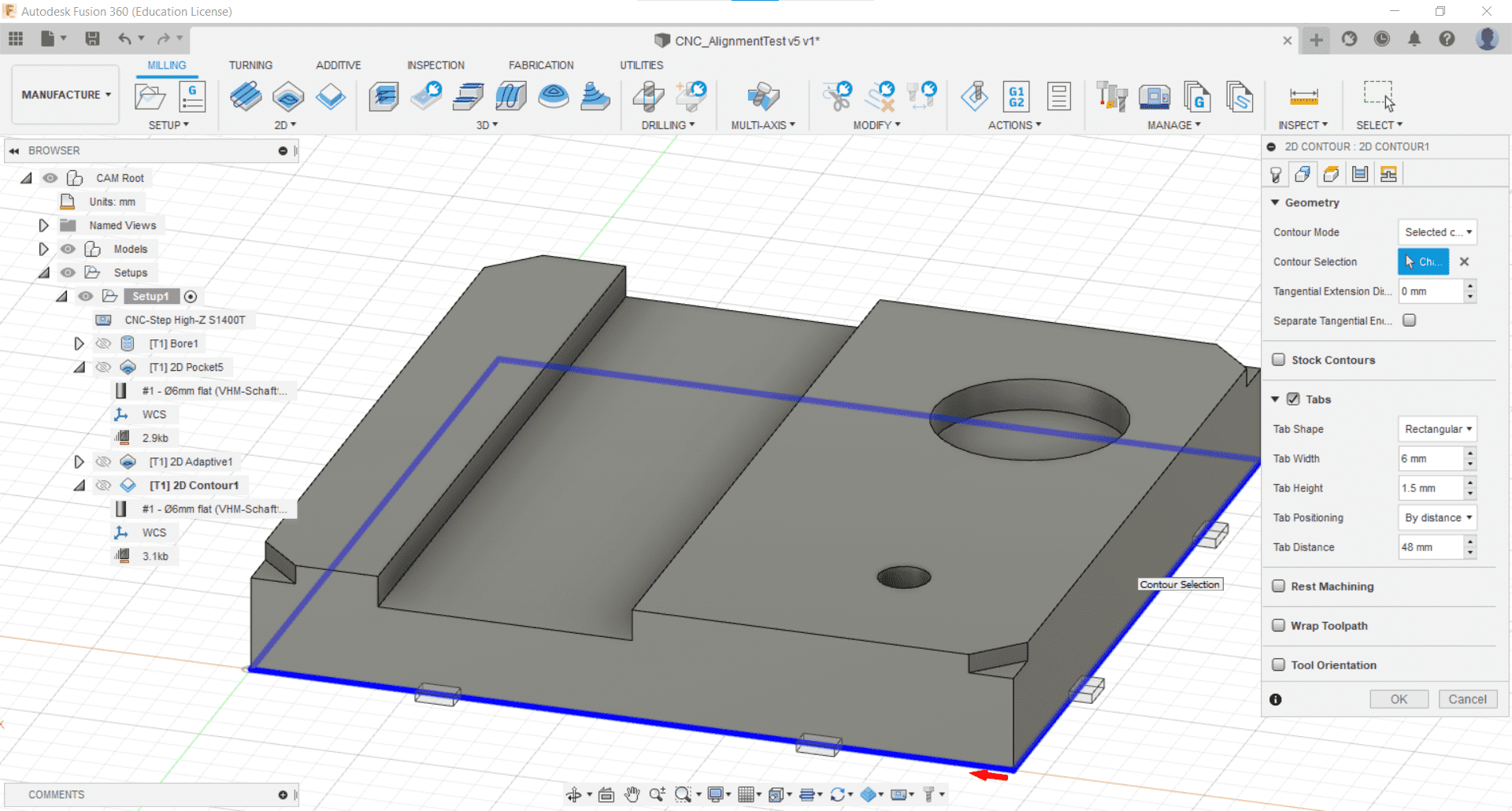
After watching the simulation, I realized that I forgot to add tabs for the cutout, so I went back into the operation by double clicking it and added them. I clicked the box and kept the default parameters.
Post-Process
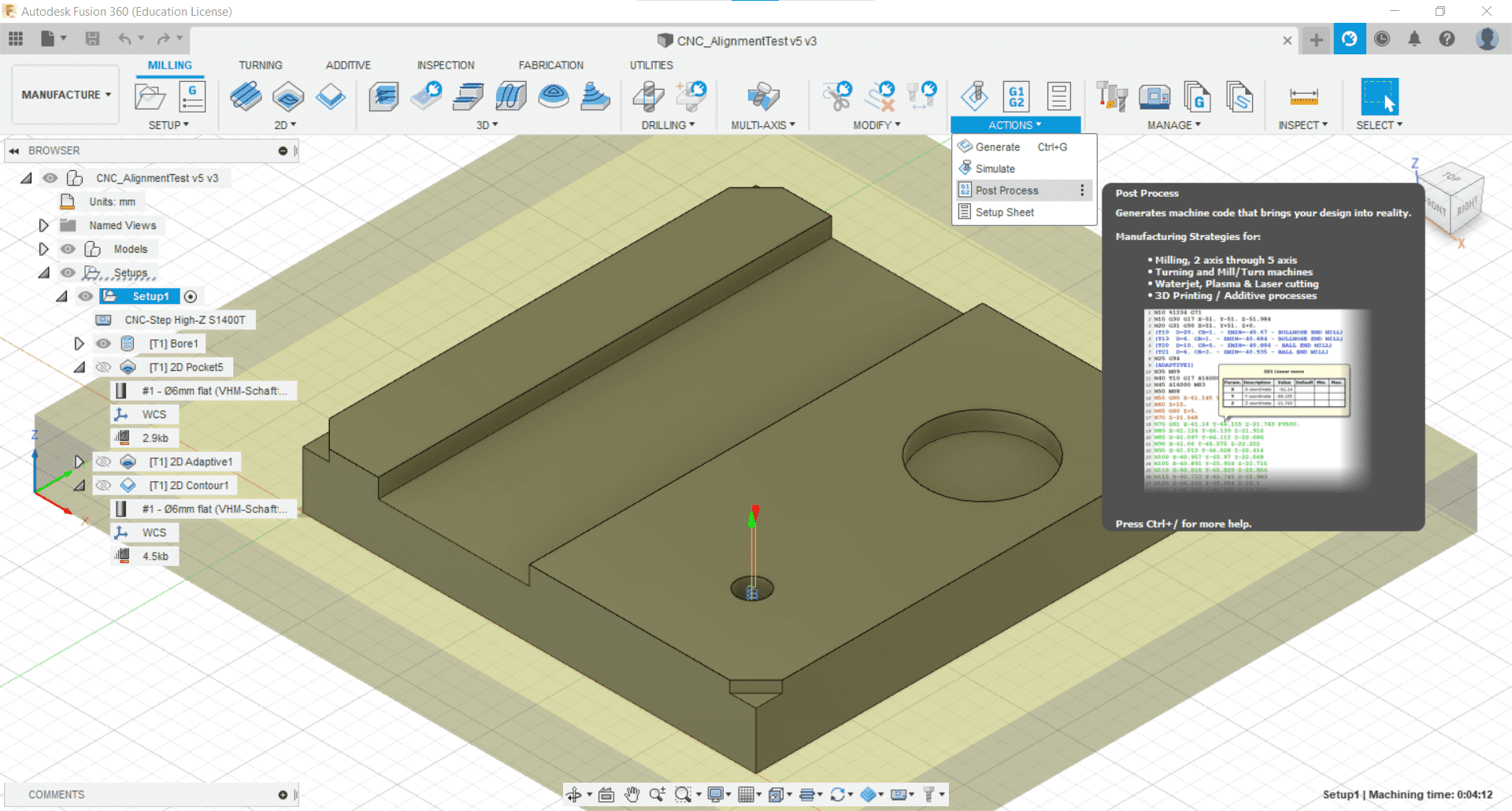
When the CAM was complete, I used the Post Process tool from the Action tab to generate the g-code for the CNC machine.
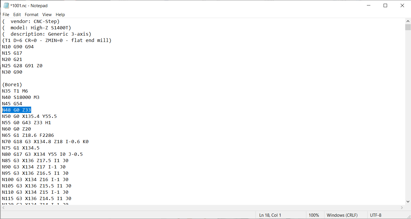
Checking the G-code
Warnings and Good Advice
I was warned by the director of my lab that, for some unknown reason, the post processing from Fusion 360 for our machine always adds a few reckless lines of g-code at the beginning and end of the CAM, such as what he referred to as a "homing dance." He advised me to learn what this handful of commands do, figure out why they are there, remove them if necessary or useful, and to simulate the entire g-code file, rather than just the pre-processed operations in Fusion. He also advised me to remove the tool after I setup the job and to run the CAM once just cutting air so I could make sure that there were no surprises when it came time to do the actual cutting. I was alone in the lab the day I was cutting so these warnings made me paranoid and I spent a lot of time checking and double checking the CAM and setup.
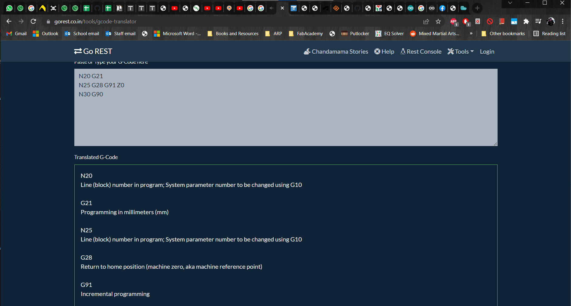
G-code Simulator
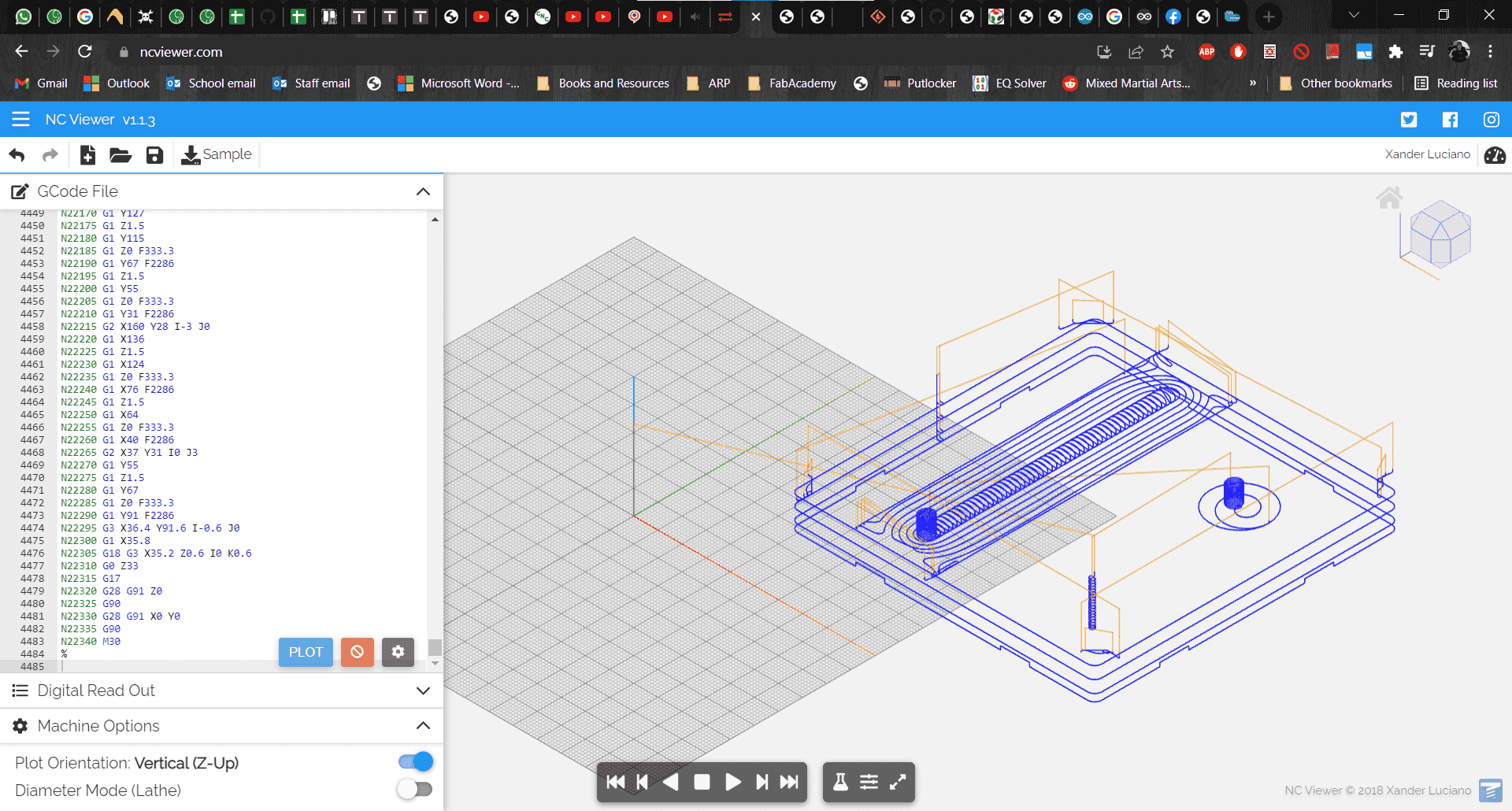
I also found a really useful and easy to use g-code simulator. With these two tools, I discovered that Fusion had in fact added a combination of lines that would have caused the tool to crash with the very first movement.
Fixed
For some reason, the first movement command after the "homing dance" only contained instructions to move along the x- and y-axes. Since the z-axis was still at 0 at that point in the code, this would have caused the tool to collide with the workpiece. So I added a new line of g-code telling the machine to move up in the z-axis before executing the command in the x and y directions.
Cutting
Fixing the Parts to the Machine
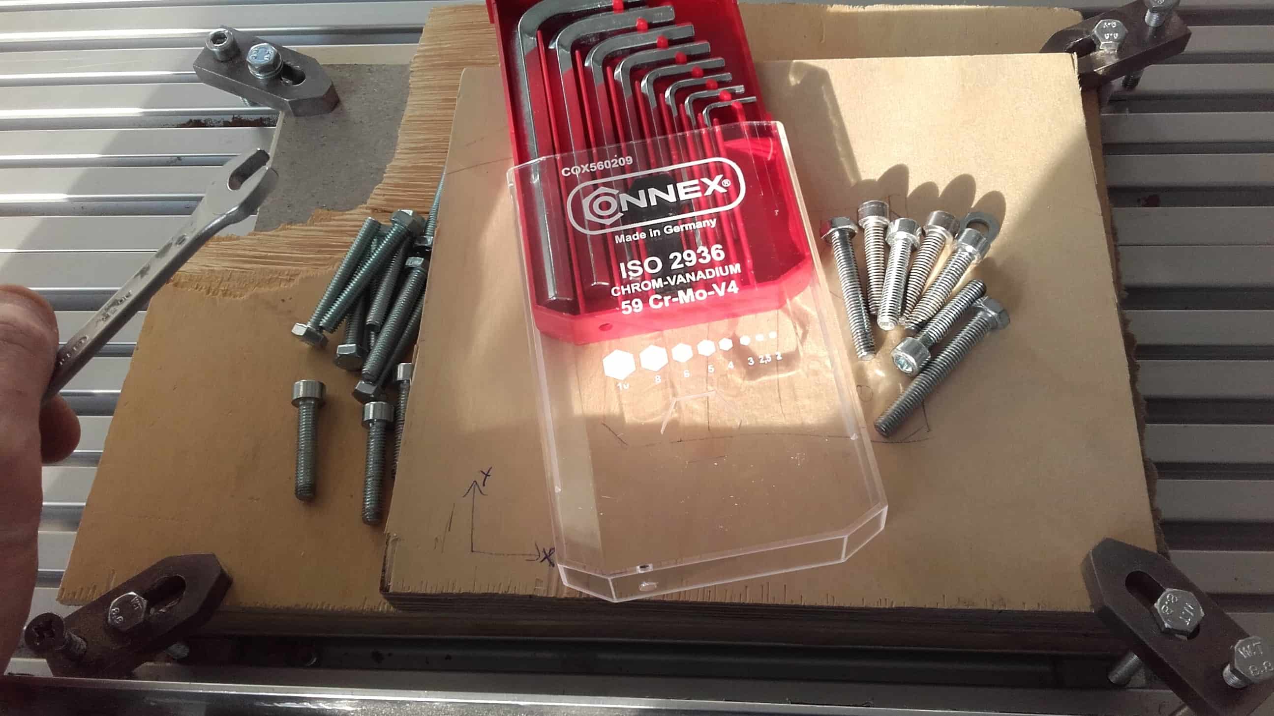
First, I attached the stock piece and the sacrificial material to the bed using clamps.
KineticNC
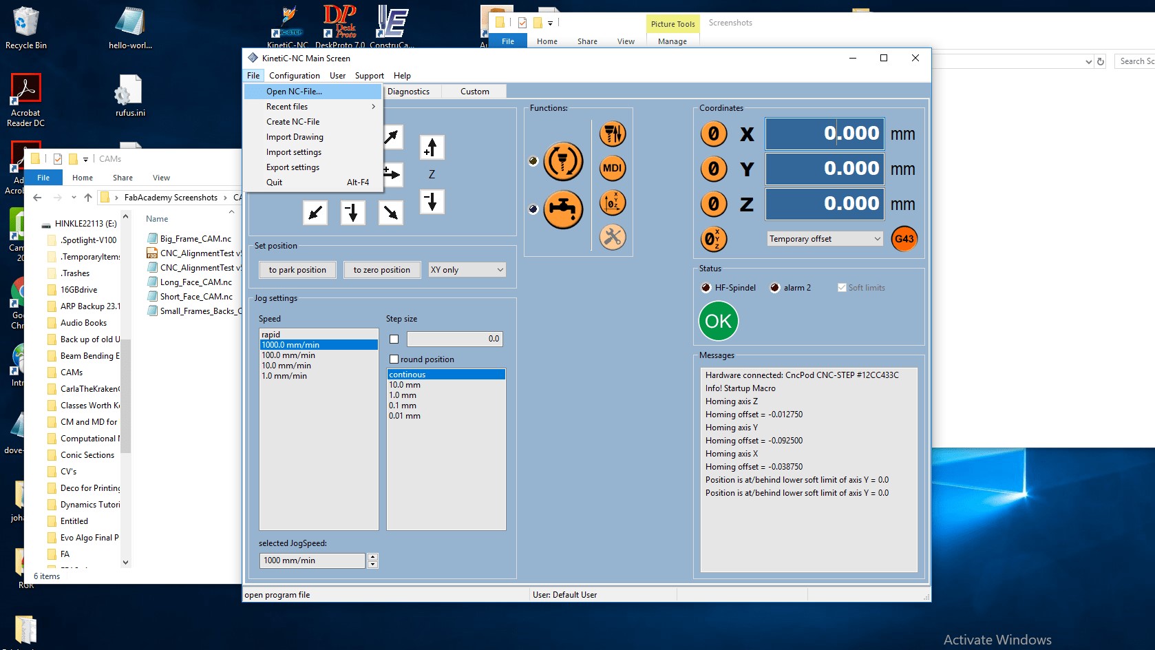
Then I opened up the KineticNC software and set the physical origin to that of the CAM using the Jog/Setup tab.
M3 Error
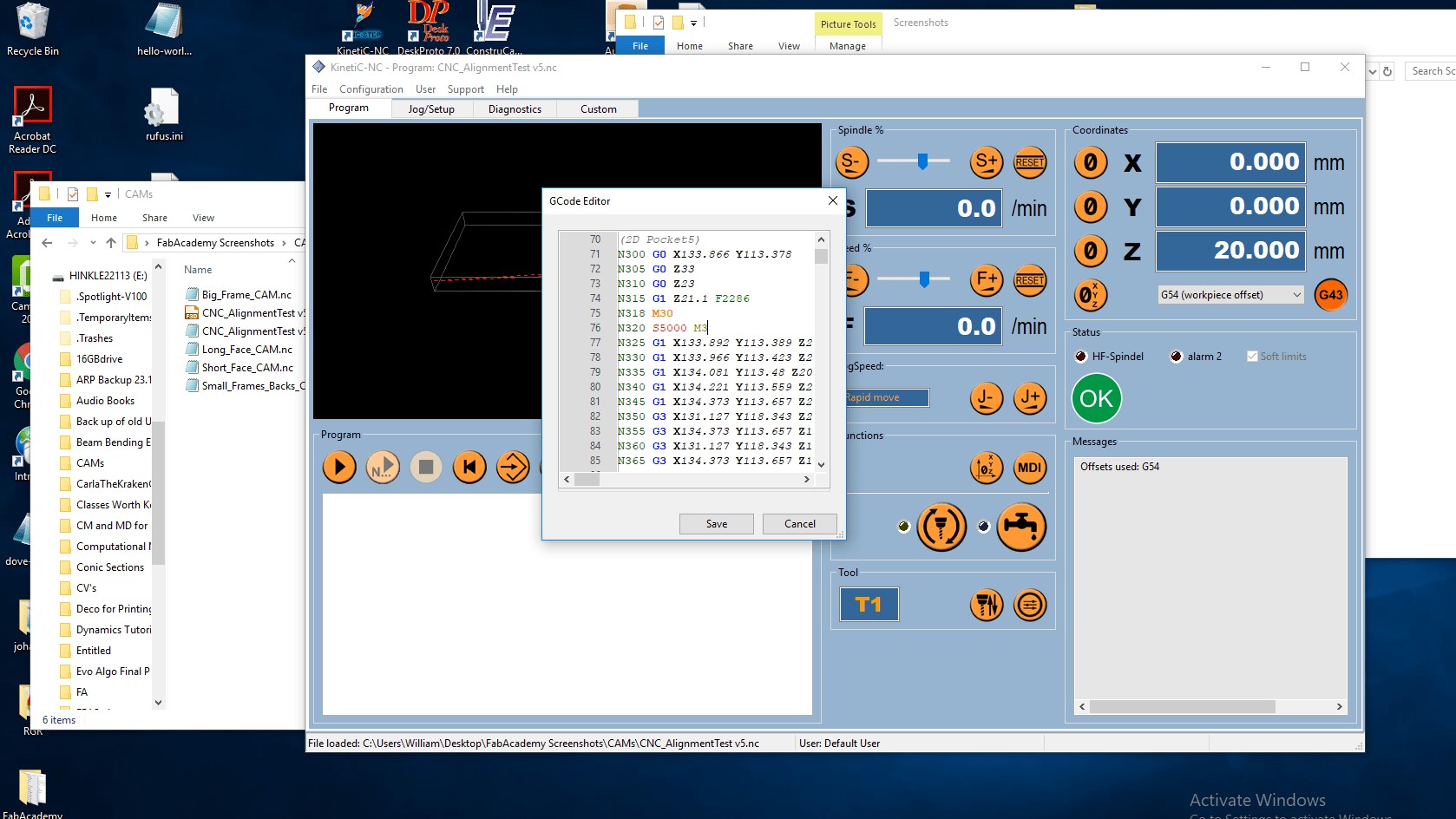
Then I discovered another minor issue with the g-code. The command "M3" gives instructions for changing the spindle speed from zero. It belongs at the beginning of the first operation, but if the spindle is already moving, then the command will generate an error. For some reason, the post processor added it to each operation for this CAM so I had to remove it from all but the first.
Play
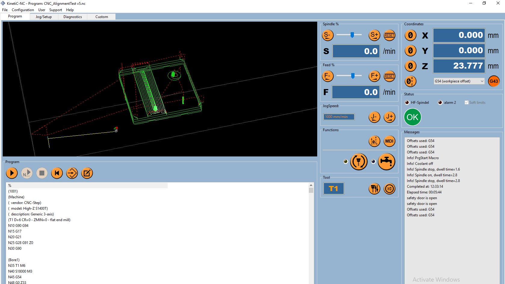
The g-code was finally looking good and I was ready to cut, so I went over to the Program tab and clicked the Play button. After a trial run cutting only air, I inserted the tool back into the collet and finally started actually cutting wood.
Cutting
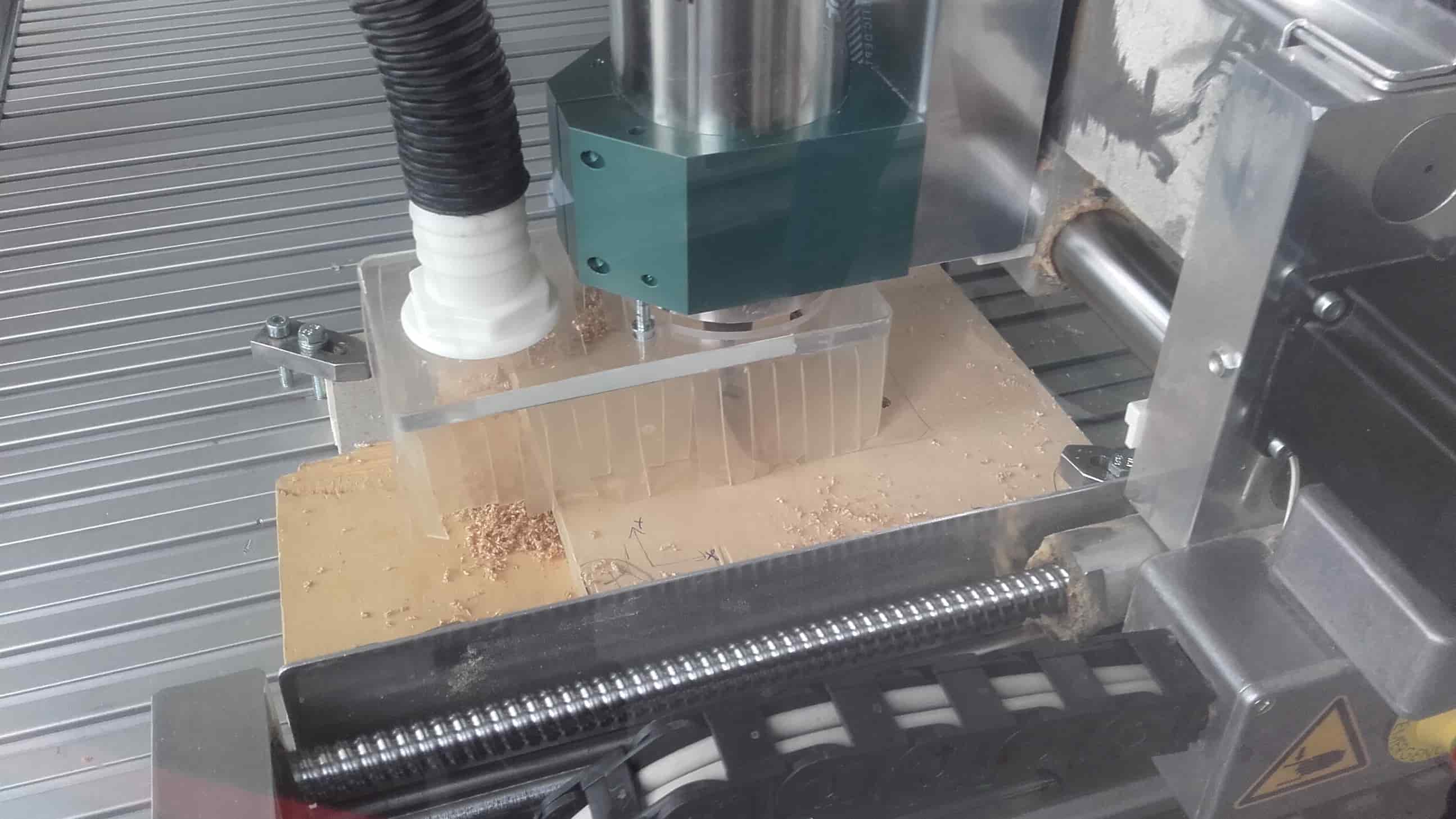
The machine did its thing while I carefully watched with my hand on the Emergency Stop button.
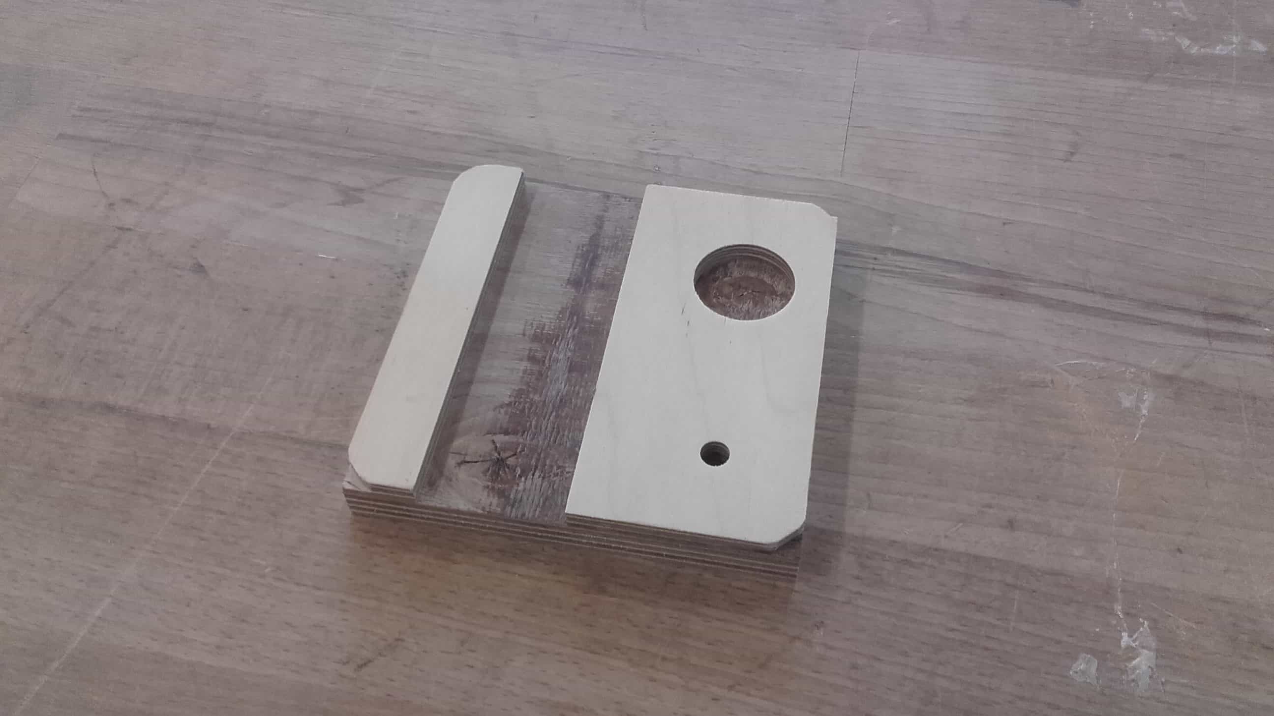
Success
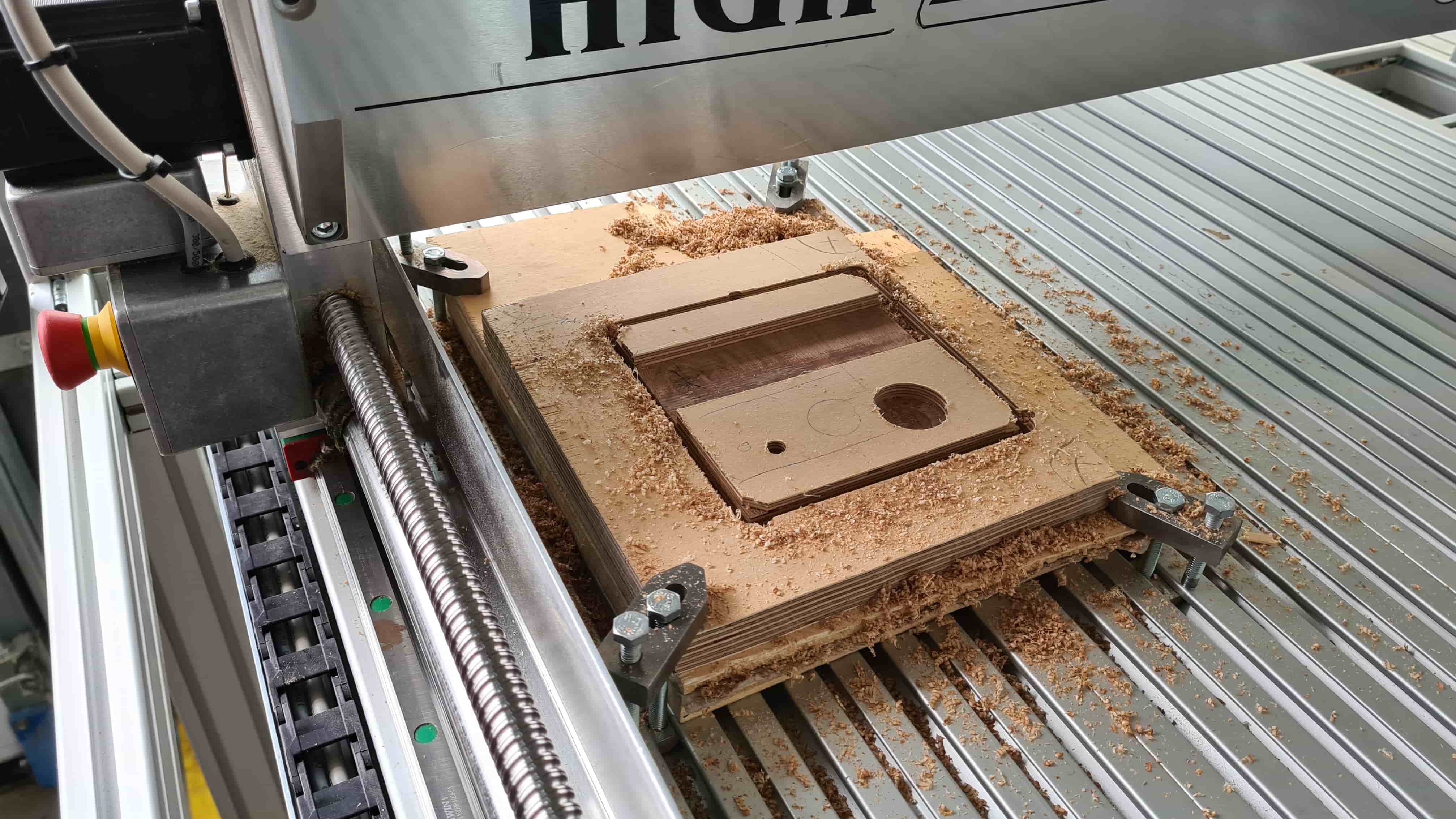
The part came out ok.
Not Great

Just ok.
Not Terrible
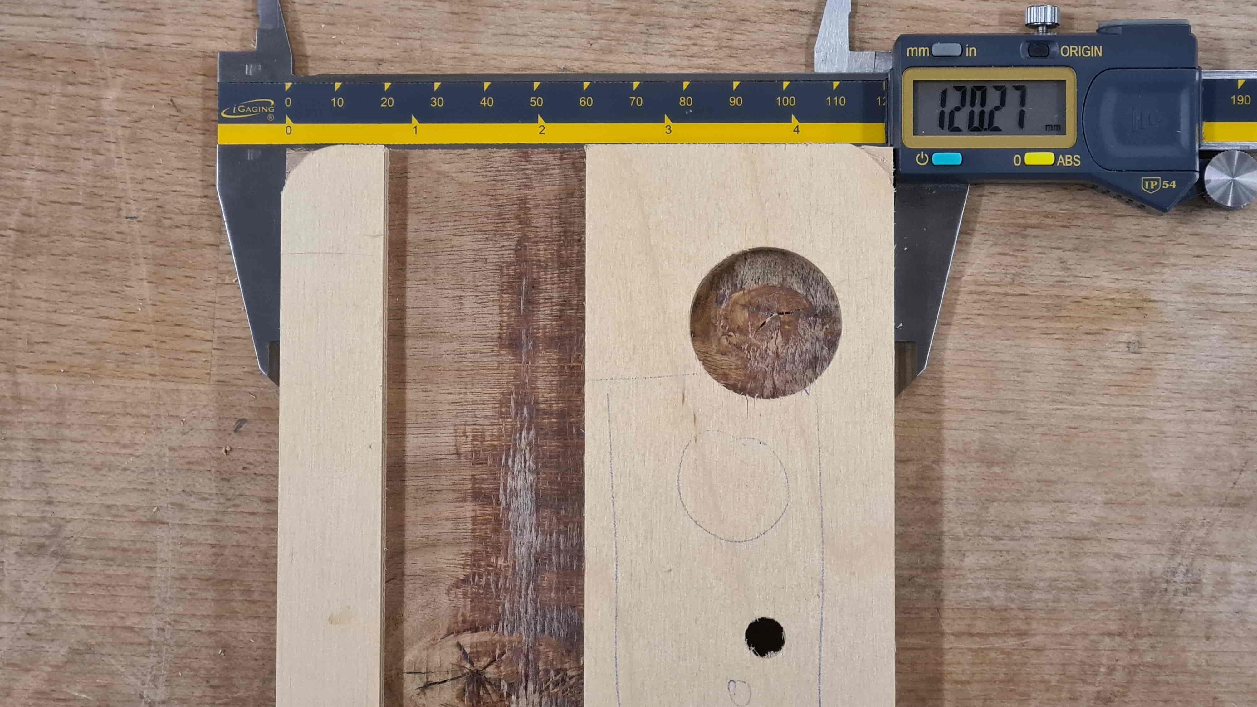
But really not so bad.
Success
Here it is after sanding it a bit and cleaning up the tabs.