3. Computer Aided design
This week I explored different CAD softwares for both 2D and 3D design.
Background - 2D-CAD
Over the years I have used a variety of 2D-design programs. I never bothered much with MS Paint, but early on got into basic raster image editing with GIMP. When I discovered vector editing, I never really went back to using raster images for anything, really. I’ve been using Inkscape for a number of years now and feel quite comfortable using it. Most of my work I try to keep in vector shape as long as possible and only render out raster images where and when absolutely necessary. After acquiring a simple Wacom Intuos graphics tablet, I also dabbled quite a bit in Krita, which is an awesome digital drawing software.
Why is Vector Better Than Raster?
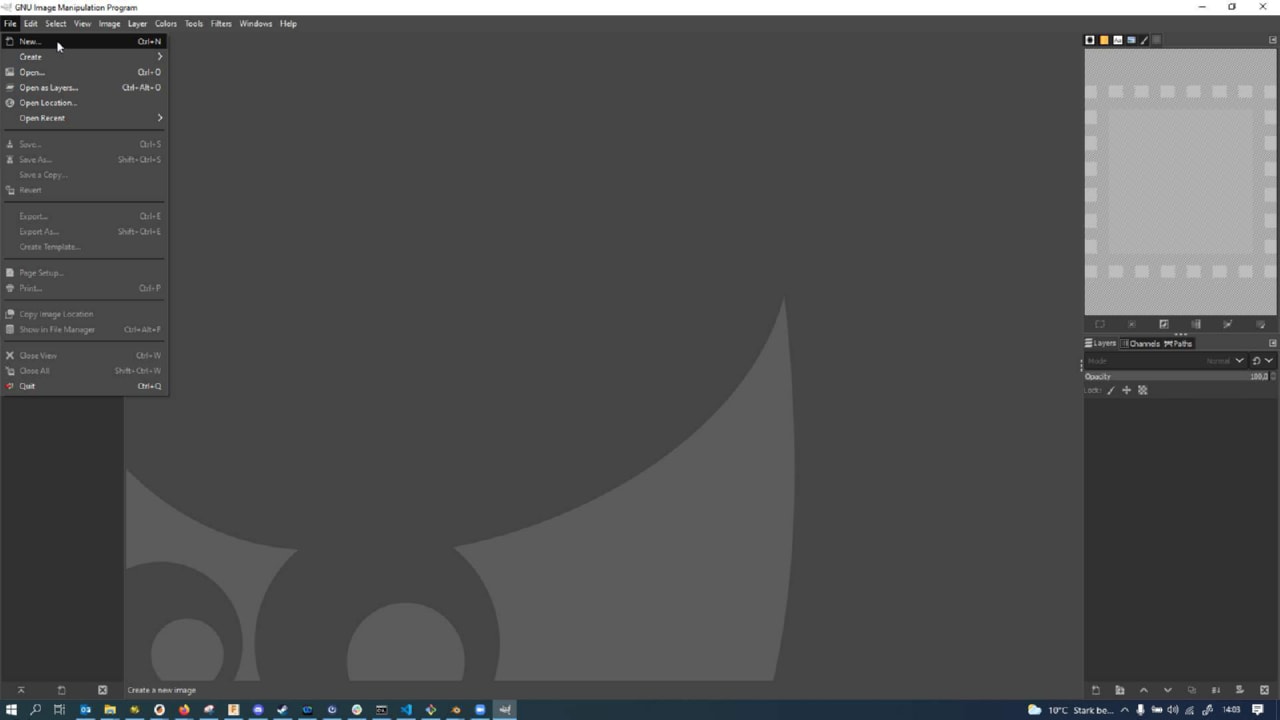
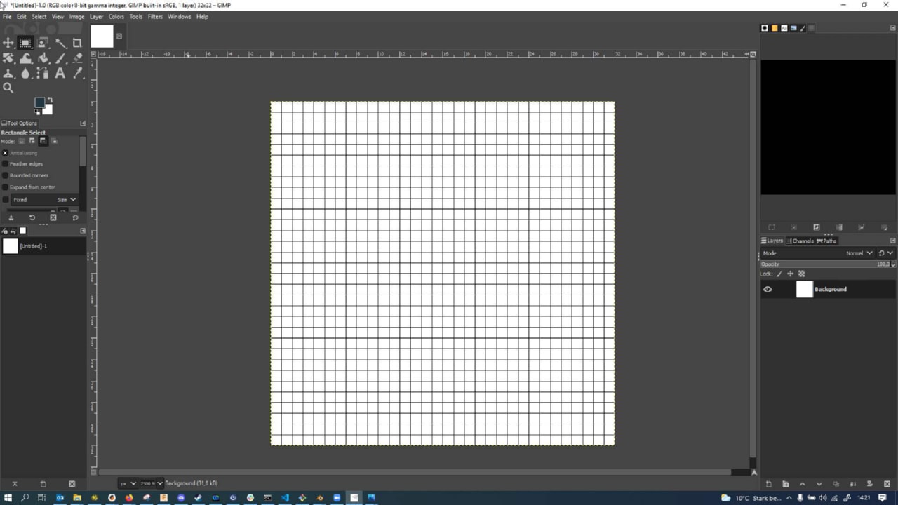
Way to go, starting a section with such a bold claim in the heading. To see why vector graphics, for the most part, are superior to raster graphics, we have to look at some of the limitations (and why sometimes they can be good) of raster graphics. To illustrate my point, I created a new, empty raster graphic in GIMP 2.10.22. GIMP si short for Gnu Image Manipulation Program and one of the most famous open source alternatives to Adobe Photoshop and similar. It is at its core a raster graphic manipulation program, with very limited functionality for vectors (it is certainly not its strong suit).
To create a new image in GIMP, we have to press File -> New:
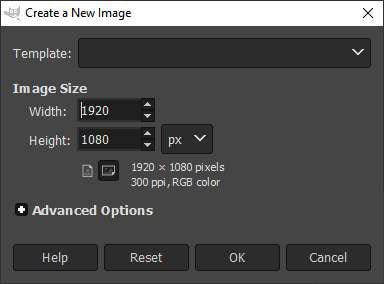
The new file dialog then prompts which size we want to work at. This is already a big difference in vector vs raster graphics. In vector graphics, we don’t usually think about an image resolution for a long time. Here, we have to decide beforehand. The standard preset is for a Full HD picture, but that’s way too many pixels for our small showcase…
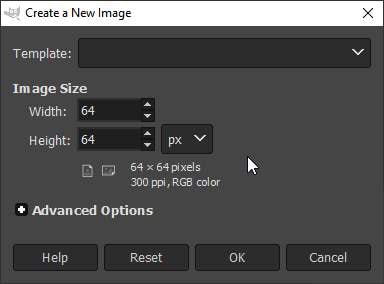
…so I changed the image size to be 64 by 64 pixels. This is our main constraint in raster graphics. Essentially, we are setting up a number of bins here that we can color in later, no more, no less. If we decide down the road that we actually needed more bins (or pixels), this creates problems:
Activating the raster view (using the # key), we can see the boundaries of the pixels. Or rather a predefined grid. In our case, the grid is not actually a 1x1 grid…
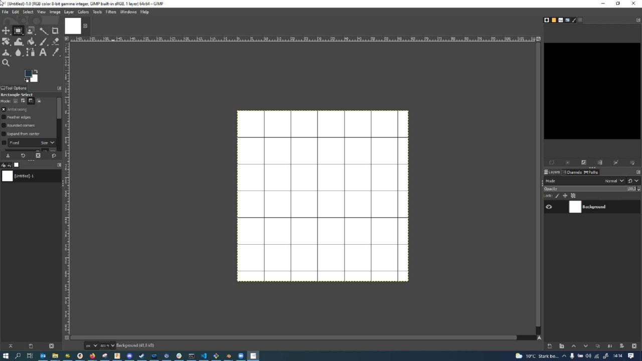
…which we can see by going to Edit -> Configure Grid:
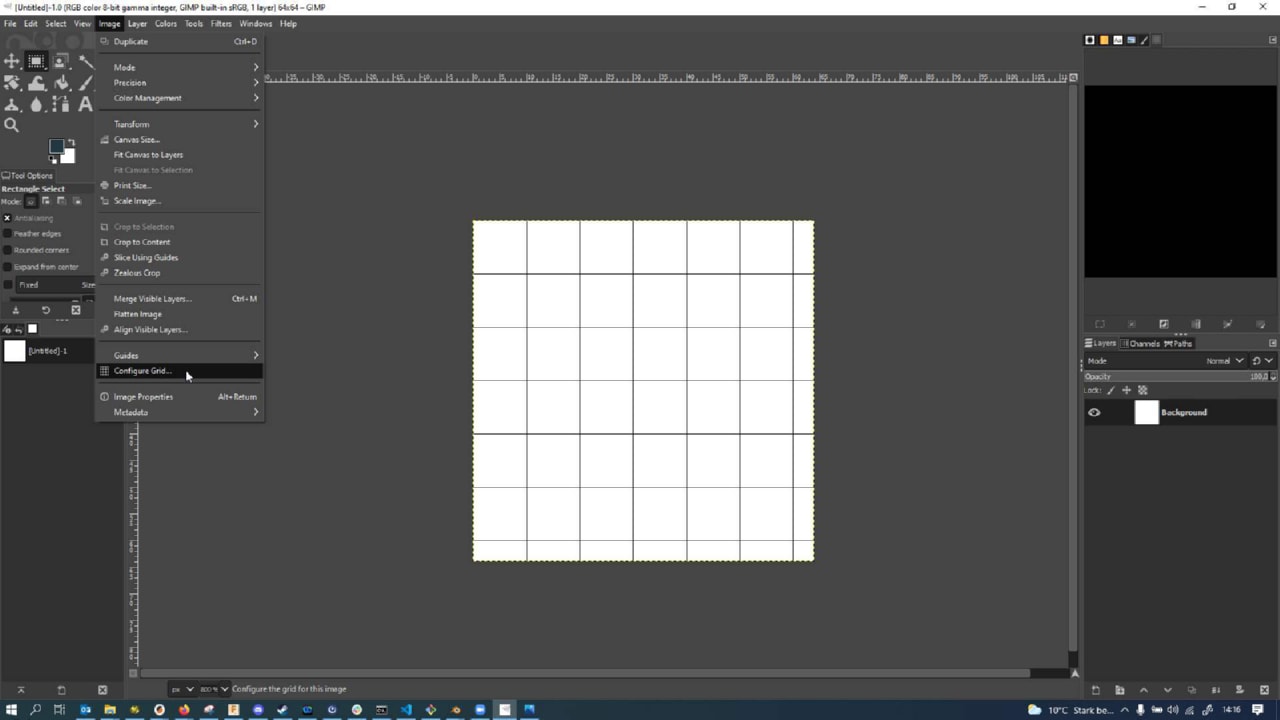
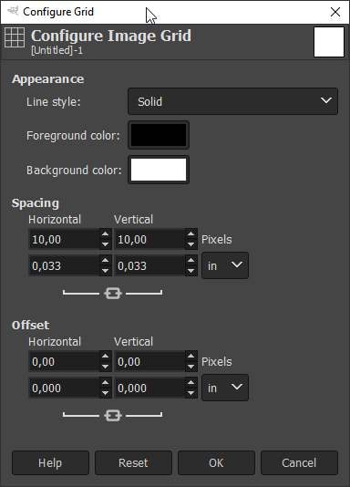
The grid that was set up for us was 10 x 10 pixels:
We can change this to 1 x 1 pixel…
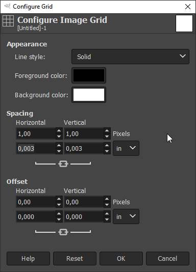
…though this was actually to fine even for the small 64x64 pixel graphic. I thus decided to go halfsies in each dimension (so quartersies regarding total pixel count)…
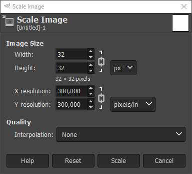
…and made my picture 32x32 pixels wide. Here shown with the full 1x1 pixel grid:
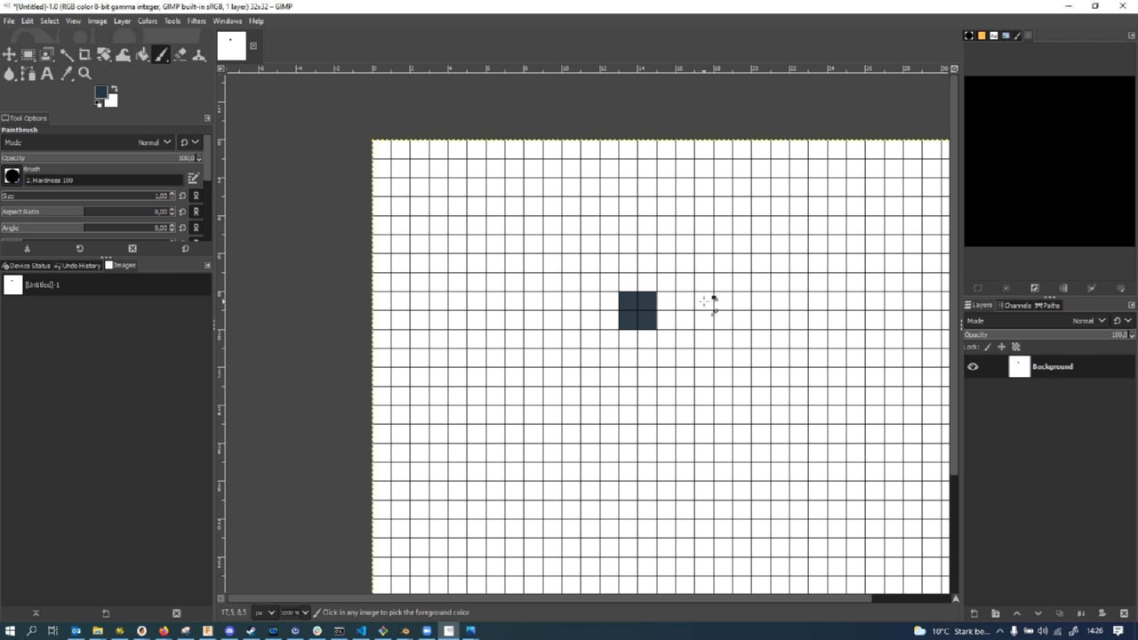
We can now start coloring in pixels. Most of the digital painting tools (brushes) we can use are actually of a certain size, in this example, the brush actually made a dot larger than a pixel. It is also not fully opaque. Pixels can contain a grayscale or color and also a transparency value, so that pictures overlaying each other can stack like transparency sheets. If we just keep going at the same spot…
![]()
…at some point the opacity value is maxed out though and the pixels are actually filled with an opaque color:
If we use a different brush tool in GIMP, we can also paint in single pixels with full opacity directly - there are tons of brush tools to choose from though and this would be too much for the sake of the experiment:
![]()
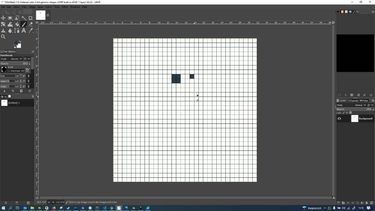
If we don’t care about colors or transparency values, we can also force the picture to be black and white (without grayscales even) by forcing it to two indexed colors only:
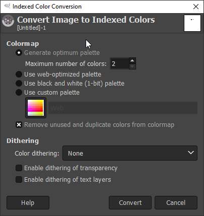
The result is not much different from what we had before, but the picture is now constrained in a way that we couldn’t even create colored or grayscale pixels anymore, wven if we tried with a brush.
The whole limitation to defined pixel boundaries is not very helpful when trying to create source files that are universally usable. I usually try to work in vector programs as long as possible, only to export a raster graphic from my vector graphic at the very last steps. Mind you - this is a one-way street: Going from a vector graphic to a raster graphic is usually possible without any problems, the other way round does not work, since vector graphics contain more information than raster graphics. In a way. Enough of raster graphics though. Let’s get working with vectors.
Working with Vector Graphics
To illustrate how flexible vector graphics are I will run through a process of tracing a physical object into a vector graphic here. The vector file can then be universally used for print output, masking, cutting, milling and a variety of other jobs.
First things first: I used a flatbed scanner to scan the logo I wanted to digitize, together with a ruler printed at 1:1 scale. I then imported the picture into GIMP, selected the important part (logo and ruler) and cropped the image…
![]()
…yielding following cropped image:
![]()
I then copied the logo over into Inkscape just using the clipboard:
![]()
I then also selected and copied the ruler…
![]()
…and pasted them into Inkscape:
![]()
I then added a horizontal orientation line into Inkscape…
![]()
…and rotated the ruler using the rotation handles…
![]()
…until it exactly aligned with the horizontal helper line
![]()
I then added another helper line for measuring and aligned it exactly with the ruler’s grid start:
![]()
Making sure that the outline of the helper line was set to a thickness of 0 mm (so there was just fill and no outline)…
![]()
…I elongated the helper shape exactly so it would align with the end of the 150 mm ruler, too:
![]()
The shape that spanned the ruler from 0 to 150 mm was (in Inkscape) exactly 940.508 mm long:
![]()
By dividing 940.508 mm by the 150 mm of the real ruler, the oversize factor was determined to be 6.27005333:
![]()
To scale the imported images in Inkscape to proper real world size, all items (except for the measurement helper object were scaled by dividing their size over 6.27005333:
![]()
This meant that the logo and ruler in Inkscape were now perfectly aligned with real world measurements:
![]()
I started tracing the logo by creating the outer ring, using a translucent red filling to see when it would match up with the actual logo best:
![]()
Using the Bézier line tool in Inkscape I then went ahead and manually traced the letters. For the L letters this was pretty simple, as they only contained horizontal and vertical lines:
![]()
For the E in the middle of the logo I actually made a helper outline shape using a square…
![]()
…that I then sheared into a parallelogram by using the corner handles until it fit the outline of the E:
![]()
Here it is (without a filling, just the outline) overlaid over the E as a starting shape:
![]()
I then added single lines to trace the E…
![]()
…and refined them…
![]()
…until all strokes were covered and trimmed properly:
![]()
I then used the Path -> Combine function to combine the single paths into a joined path object:
![]()
After some nudging and fixing, the E was properly traced (here shown with the outline active again):
![]()
After cleaning up double nodes some more and also tracing the D, the logo was pretty much done:
![]()
I then copied just the path objects to the side to isolate it…
![]()
…and then also copied it into a fresh file:
![]()
A good thing to do regarding cleanup is always to crop the image where possible (if not working on full page designs), so I cropped the vector file to the bounding box of the logo…
![]()
…yielding a much more compact file (size-wise, not file size wise):
![]()
Another standard step when trying to work with vector files in another program later is to make sure that all Objects in Inkscape are actually converted into Paths. I selected all and everything on the page and converted the objects into paths:
![]()
Before importing the vector file into Silhouette Studio for cutting later, I needed to export the vector file into DXF format, as Silhouette Studio does not support SVG files in its free license. There are two DXF formats possible: standard and R14. I tried both here. Going through the standard DXF format, the round shape of the vector path was actually not conserved and there was some angulation:
![]()
When using the R14 format as an intermediary, this worked out much better keeping the curvature intact…
![]()
…but even then, a little bit of jankiness remained (e.g. see here at the right side of the circle there is a slight sharp angle in the curvature:
![]()
When setting up the vector shape as a cut,…
![]()
…a problem became apparent: the E in the middle of the logo would weirdly cut twice as it overlapped the other letters:
![]()
The vector could be split into separate, smaller vectors though in Silhouette Studio directly (so there were separate vectors for the letters and double cuts could be prevented by setting the shapes to weld together and then only cutting their combined outline:
![]()
In the end, I set up the file to be cut in multiple stages, although I messed up the order slightly where it would cut the outline first (although when using the vinyl cutter to cut this is not as crucial, as the backing material still holds the material in place):
![]()
This would serve later as the basis for the Computer Controlled Cutting Assignment.
Background - 3D-CAD
Having worked with a number of different 3D-CAD systems in the past, I do consider myself an advanced 3D-CAD user in general. My focus nowadays is on programmatic 3D-CAD, but I do occasionally like the ease of use of 3D-GUI-based 3D-CAD systems, too.
In university, I started out my 3D-CAD journey learning Siemens Solid Edge. When I went on to another university, I was briefly forced to use Dassault Systèmes SOLIDWORKS, but never really got comfortable with the - in my books - clunky interface. After finishing my studies, when I got my first 3D-printer, the need for a (preferably free) 3D-CAD program arose again. I dabbled a little bit in FreeCAD (free software project), which just crashed constantly and was nigh unusable for me back then (a few years back). The only real alternative at that point in time was Autodesk Fusion 360, which had a hobbyist license and was free to use. The interface reminded me a lot of Google1 SketchUp, which I had used prior to using actual 3D-CAD programs for hobbyist work. Fusion 360 quickly became my daily driver for generating print designs, but at the same time I decided to explore programmatic 3D-CAD as well, so I decided to learn OpenSCAD (free software project). For a few years I have now rocked that combo, using Fusion 360 for intricate designs or exploring new designs and using OpenSCAD to take a few of those designs and making them bulletproof afterwards… More on that later :)
Besides that, I have used Blender for ages for mesh-based 3D-Modeling, animations, renders, messing with the various simulation systems etc. I still use it today for rendering outputs from 3D-CAD software, as the free version of those softwares are often a bit limited in their rendering capabilities. Blender also comes in handy when manipulating mesh files, e.g. for 3D-printing, when no source 3D-CAD files are available.
Programmatic 3D-CAD vs. GUI 3D-CAD
GUI-based 3D-CAD software is certainly the more common way to do 3D-CAD modelling when compared to programmatic 3D-CAD. In GUI-based CAD, the user directly creates and manipulates shapes or bodies in 3D space to achieve the desired result. This usually happens by sketching a shape and then extruding said shape into a three-dimensional body, akin to pressing dough through a cookie press to create a body from the stencil shape.
Programmatic 3D-CAD software usually does not have a GUI for manipulating objects - the creation of bodies and shapes takes place entirely in code. To enable the user to see the effects of her code, such 3D-CAD systems usually have an immediate preview of the programmed shapes and (optionally) a later step to render the preview into an actual body of some sort.
In my experience, both types of modelling have their own pros and cons. Since I am most familiar with OpenSCAD and Fusion 360, I’d like to compare these two in regard to some key points:
| Programmatic (OpenSCAD) |
GUI-based (Fusion 360) |
|
|---|---|---|
| Learning | Somewhat hard to learn | Easy to learn |
| Imagination | Requires good imagination to achieve desired result | WYSIWIG - What you see is what you get |
| Personality | Affinity for coding beneficial | Visually appealing even if you don’t like coding |
| Parametrization | Can be made pretty bulletproof Easy to generate features where count is unknown beforehand |
Can explode at the slightest change if not designed carefully Often hard to generate features of yet unknown count parametrically |
| Preparation | Needs a lot of thinking ahead, very deterministic | Design often generated on-the-fly, many features relate to other features |
| File transfer | Does not generate STEP files, only meshed output | Generates STEP files for easy exchange with other CAD-programs |
| Automatization | Can be run from the CLI, can run on servers and output files as requested by clients | Can probably not be run on a backend |
| Scriptability | Native, everything is a script | C#/Python Script API (haven’t dabbled yet…) |
The above comparison shows that there are some drastic differences between these two types of 3D-CAD. A GUI 3D-CAD program can yield fantastic results very quickly - usually at the cost of stability. Unless very well thought through and executed, parametric CAD models in GUI-based systems can have the tendency to fail when changing parameters later on. Often this is the case because sketches are not fully constrained (so they can move around or dimensions other than the one supposed to, change). Other times the user visually references edges that might not exist later on, catastrophically breaking the sequence of steps in generating the target body. It is usually very easy to reach an (apparently) good result that is an absolute mess behind the scenes. Since programmatic CAD often does not allow referencing of edges, all measurements have to be determined beforehand - no referencing off edges for example. This very deterministic nature makes the models way less likely to break - but it needs way more thinking ahead and a very good understanding of trigonometry at least to produce effective results.
Often times, I find my workflow is as follows: - Generate a model in Fusion 360 graphically, quickly cycling through iterations and defining key features - (Sometimes: Cleaning up the model by starting anew, making sure to implement all features very cleanly) - Realizing that the model is still not as stable and/or flexible as wanted, then recreating the generation logic in OpenSCAD
Other contenders, more options to explore
Lately, I often found the need to use the output of some OpenSCAD code in Fusion 360, e.g. for creating one-off fixtures that don’t really justify the time expense of generating them programmatically. Since this is problematic, as OpenSCAD only exports mesh files2, I’ve been on the lookout for other programmatic CAD software. A few months ago, I found out about CadQuery, which allows programming in Python and has a similar design paradigm like GUI-based software, where shapes can be generated by referencing other object planes or edges dynamically. CadQuery also outputs STEP files, which can then be easily loaded into and manipulated by Fusion 360. I’ve had a hard time getting into it, as CadQuery is still evolving very quickly and many features are in flux and/or not well documented - but there’s a lot of potential there!
Many GUI-based CAD packages, Fusion 360 being one of them, also have some kind of scripting API to automate tasks and program Add-ons and the like. I’ve tried to get into Fusion 360’s scripting API at some point, but quickly gave up, due to what I felt was a lack of documentation. Things may have evolved though and certainly warrant another look.
Creating my Prototype Render
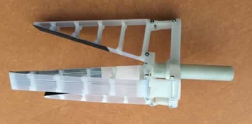
Since I was very short on time this week, I decided to generate a model using Fusion 360, render the object in there and then compare to a render generated in Blender (using mesh files exported from Fusion 360 as input). Since I was in need of a manually operated 3-finger gripper for teaching/demo purposes anyways, I decided to use that object as my target prototype. I did actually find a gripper design on Thingiverse that I liked very much, but the dimensions were way off scale for what I wanted.
 |
|---|
| The original gripper design by Thingiverse user maddinmm. |
I set out to rebuild the design myself in Fusion 360 to my target specifications:
- The gripper hand piece should have a hexagonal shape or be in some other way constrained to linear movement (the original one from Thingiverse was able to rotate the handle, too)
- The whole apparatus was supposed to work with FinRay finger elements of about 70 mm length and a certain, predetermined geometry3
- The apparatus should be way smaller thatn the one provided in the original
- I wanted to have an assembly of the full gripper, so I could move parts around as they would in reality and check for collisions
 |
 |
 |
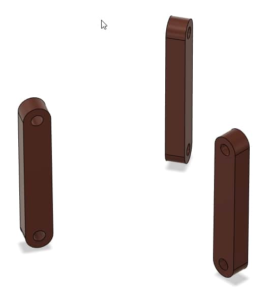 |
|---|---|---|---|
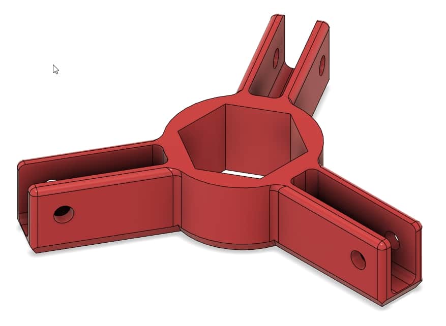
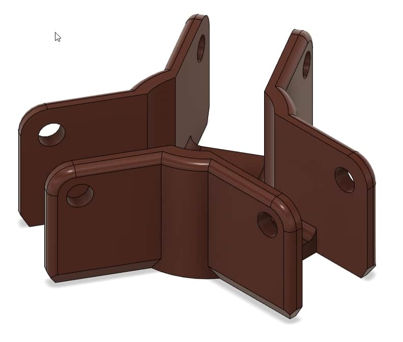
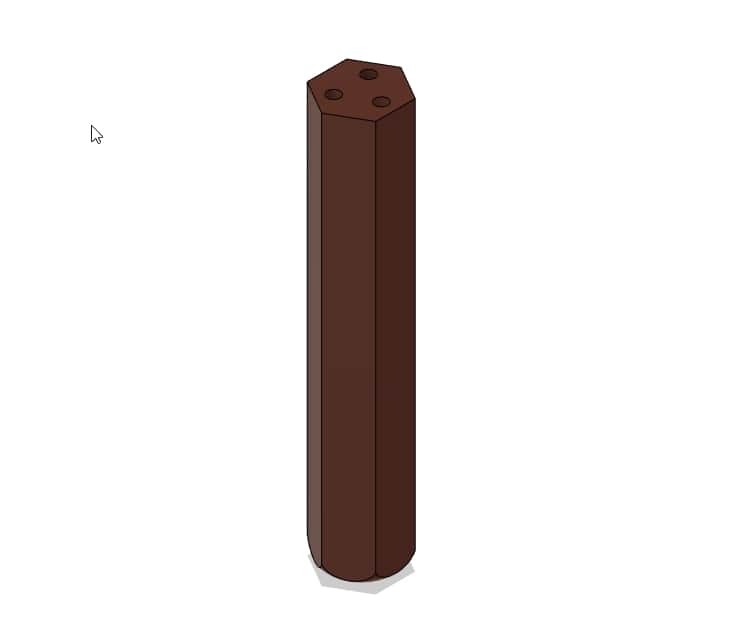
| I started out by modeling the bottom bracket of the gripper… | …then the top bracket… | …the handle… | …and the bars for the mechanism. |
After creating the single parts, I assembled them using the Fusion 360 joints tool. I also added mockup FinRay finger elements for the elements that would later be exported by my OpenSCAD generator. Most joints were set up as revolute joints, with the exception of the handle, which was set up as a sliding joint. Fastening hardware used at the rotating joints was downloaded using the McMasterCarr plugin, but hidden for showing the design.
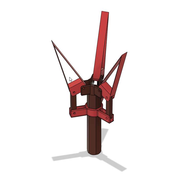 |
|---|
| The assembled gripper in the Design workbench in Fusion 360. |
I then changed the appearance of the parts to what was already shown above (red/brown) for visual appeal and to match the colors I had available for 3D-printing later. After that, I used the Fusion 360 render workbench to render the gripper as an In-Canvas render in the “Skylight” environment.
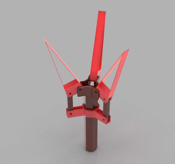 |
|---|
| The assembled gripper rendered in the Render workbench in Fusion 360. |
|
|
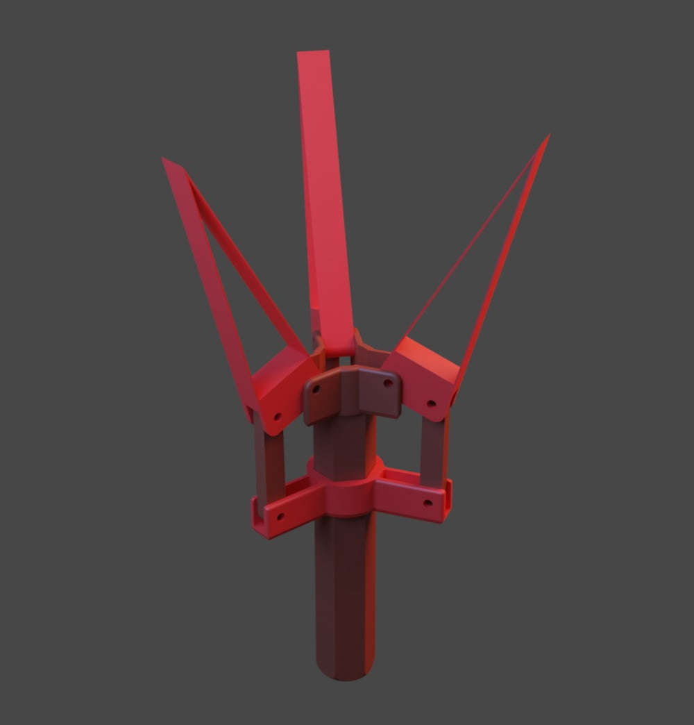 |
|---|---|---|
| The gripper as shown in the Fusion 360 preview… | …rendered in Fusion 360… | …and rendered in Blender. |
Design Files
- Gripper Design/Assembly File (F3D, Fusion360)
- Gripper Design for Rendering in Blender, with single colour source mesh files (BLEND/STL, Blender):
-
SketchUp was still a Google product back then and was only later bought by another company. ↩
-
There is a hacky workaround to generate solid bodies (as STEP files) by running OpenSCAD code through FreeCAD, but that is limited to a certain specific subset of OpenSCAD functions and has never worked for my designs. ↩
-
Generation of the finger element happened earlier in OpenSCAD and is not covered in this report. ↩