Final Project
Spoiler: Final Project Presentation Video
Hot off the presses, here is the Final Project Presentation Video:
Spoiler: Final Project Presentation Slide
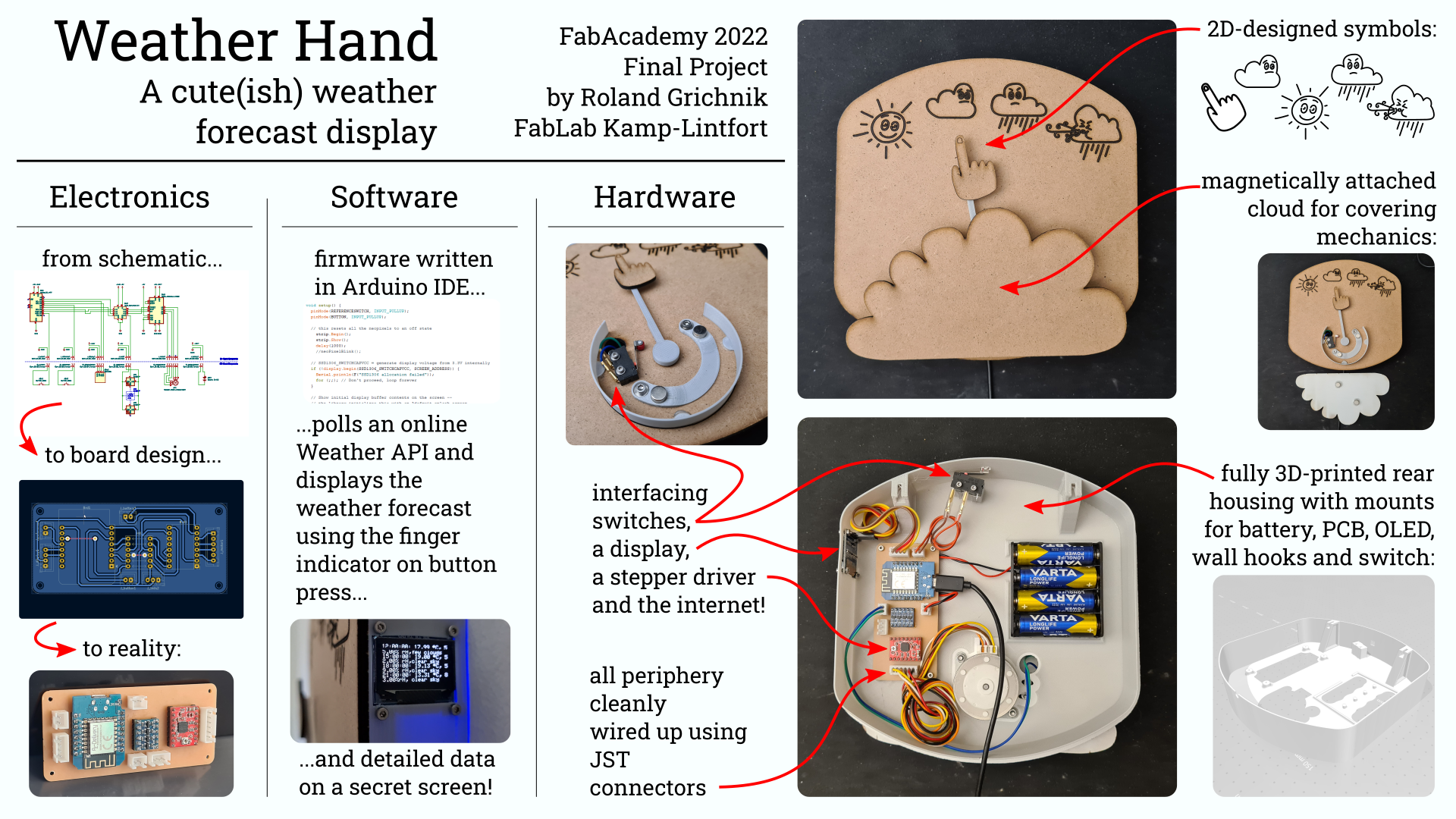
Final Idea - Children’s Bedroom Suitable Weather Forecast Display
Day -2
May 24th, 06:00 PM. It is May 25th already. Two more weeks to go until FabAcademy final project presentations and not much actual progress beyond ideas made. Buying a house, moving house, Covid isolation, sick children - a lot of factors caused this pickle. I’m starting to get nervous. What to do? I don’t want to hand in a totally simpleton project with no use, yet at the same time I am starved for ideas.
Day -1
May 25th, 07:00 AM. Did not sleep well. Besides my mind running in circles, the crew is revolting and kept me busy this night. Can’t concentrate. Getting the little ones ready for daycare. But what should they wear? What’s the weather going to be today? Reluctantly I go hunting for my phone to check the weather forecast. Then inspiration strikes - a weather forecast display.
- Ordered ESP8266 boards (for WiFi functionality)
- Went through my pile of things
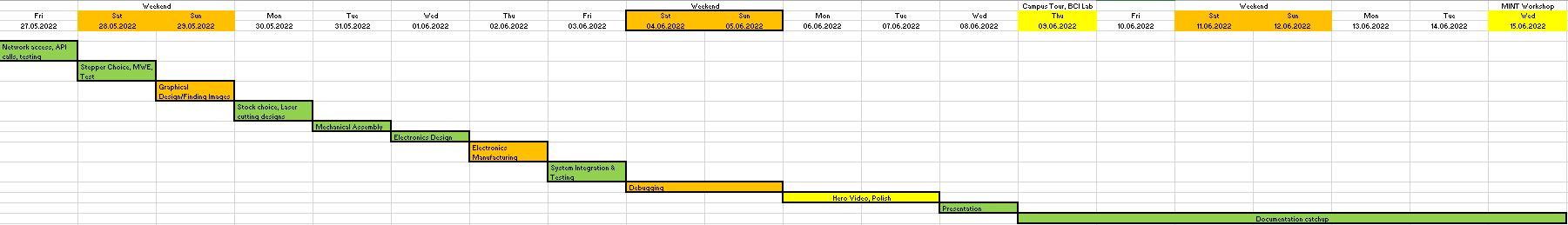
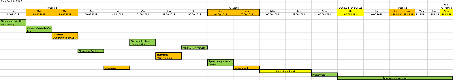
I also created a simple Gantt chart using Microsoft Excel, simply to see how many (realistic) work packages I’d be able to cram into the remaining time (also for download in the design files at the end of the page):
Day 0
Anxiously waiting for my microcontroller boards to arrive, I spent a lot of time with my children this day (Ascension Day, a national holiday) and thus didn’t make any noteworthy progress here…
Day 1 - Figuring out the ESP8266 and the Weather API
This day, my ESP8266 microcontroller boards arrived. I immediately started working on the electronics and the program logic, as I regarded that one of the harder parts to tackle (I don’t have much experience with IoT devices and embedded communication with the internet).
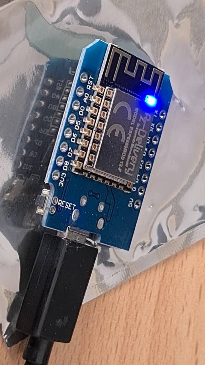
The Wemos D1 Mini board with ESP8266 processor yet to be assembled/soldered:

ESP8266 Setup
- Added http://arduino.esp8266.com/stable/package_esp8266com_index.json to the Board Manager URLs in Arduino IDE (to get access to ESP8266 board cores)
- Installed esp8266 boards in Boards Manager
- CH340 driver was already installed from working with chinese Nano clones, so no driver installation needed there
- After connecting with USB cable, device showed up in device manager as COM port
- Restarting Arduino IDE and choosing proper board (´LOLIN(WEMOS) D1 R2 & mini´)
- Uploading bog standard Blink sketch -> blinks!
- Setup complete
Here it is hooked up for the first time, blinking happily:
Figuring out basic WiFi access
- After selecting the proper board, more Example sketches are shown in Examples
- Trying specific ESP8266 Blink sketch, too (different because active LOW LED!) -> works!
- Looking through the example sketches for some basic ones, found “ESP8266WiFi -> WifiClient” to be very useful
- After entering WiFi SSID and password into the sketch and uploading to the D1 Mini board, the board connected without problems and returned its output on the Serial console (quote of the day from an online service)
Figuring out Weather API access
- Looked through a few of the projects mentioned in week 18 under “What came before”, but all this very customly tailored code was a little too obscure and hacky to actually learn what’s going on
- Then just googled for “Weather API ESP8266” tutorial
- Followed https://randomnerdtutorials.com/esp8266-weather-forecaster/ tutorial
- registered at openweathermap and got API key
- made a first API call:
http://api.openweathermap.org/data/2.5/forecast?q=Kleve,DE&APPID={InsertOpenWeatherAPIKeyHere}&mode=json&units=metric&cnt=2 - resulted in “First Forecast.json”
- by the “cnt” in the API call at the end determines how many time slots are queried (in 3-hour blocks). E.g. a value of
2returns the current as well as the +3h weather data - by changing the value to
4, much more weather data can be polled:http://api.openweathermap.org/data/2.5/forecast?q=Kleve,DE&APPID={InsertOpenWeatherAPIKeyHere}&mode=json&units=metric&cnt=4 - resulted in “Second Forecast.json”
- By the tutorial, we now want to do the whole thing from the ESP8266
- Installed ArduinoJSON library (though through board manager, not manually, let’s see wheteher this will work)
- (Reason it might not work is the website links to a tutorial about version 5.13.5 of the library and also provides a link to that version, the latest one available through library manager is much more recent though! I installed the most recent for testing)
- Other than that, copied the code from the tutorial, added my SSID and PSK and API key into the sketch
- Lo and behold, upon compiling I got an error message that one of the objects was from ArduinoJSON 5. Time to install the older library then.
- Compiled and uploaded fine
- Board connected to WiFi, but seemed to not be able to connect to OpenWeatherAPI (or unresponsive, nothing happening beyond connecting to WiFi):
connecting
.......WiFi Connected
SSID: FRITZ!Box 3490
IP Address: 192.168.178.78
signal strength (RSSI):-64 dBm
- Then subsequently added (or commented out some were already there) some debug messages on the Serial console to find out where it got stuck (here added “connecting… when trying to connect to the server):
connecting
.......WiFi Connected
SSID: FRITZ!Box 3490
IP Address: 192.168.178.78
signal strength (RSSI):-70 dBm
connecting...
- Here also printed out the combined HTTP request string to make sure String concatenation worked fine:
connecting
.......WiFi Connected
SSID: FRITZ!Box 3490
IP Address: 192.168.178.78
signal strength (RSSI):-68 dBm
connecting...
GET /data/2.5/forecast?q=Kleve,DE&APPID={InsertOpenWeatherAPIKeyHere}&mode=json&units=metric&cnt=2 HTTP/1.1
- Here I added two more debug points when closing the connection with the server (or rather closing the client object) and when no timeout was detected:
connecting
.......WiFi Connected
SSID: FRITZ!Box 3490
IP Address: 192.168.178.78
signal strength (RSSI):-68 dBm
connecting...
GET /data/2.5/forecast?q=Kleve,DE&APPID={InsertOpenWeatherAPIKeyHere}&mode=json&units=metric&cnt=2 HTTP/1.1
closed...
no timeout...
- Everything hinted at everything actually going fine, but me just not seeing any results (also because there is a very long delay of 10 minutes between API calls, there is not much action). I then added a Serial printout for the JSON string when parsing and got following result:
connecting
...............WiFi Connected
SSID: FRITZ!Box 3490
IP Address: 192.168.178.78
signal strength (RSSI):-73 dBm
connecting...
GET /data/2.5/forecast?q=Kleve,DE&APPID={InsertOpenWeatherAPIKeyHere}&mode=json&units=metric&cnt=2 HTTP/1.1
closed...
no timeout...
HTTP/1.1 200 OK
Server: openresty
Date: Fri, 27 May 2022 16:39:13 GMT
Content-Type: application/json; charset=utf-8
Content-Length: 984
Connection: close
X-Cache-Key: /data/2.5/forecast?APPID={InsertOpenWeatherAPIKeyHere}&cnt=2&mode=json&q=kleve,de&units=metric
Access-Control-Allow-Origin: *
Access-Control-Allow-Credentials: true
Access-Control-Allow-Methods: GET, POST

{"cod":"200","message":0,"cnt":2,"list":[{"dt":1653674400,"main":{"temp":16.12,"feels_like":14.7,"temp_min":13.68,"temp_max":16.12,"pressure":1021,"s
- It seems like the server actually returned something, but there was something fishy going on in the parsing. I decided to rework that area a bit to also fit my later use case - knowing whether it would rain over the day (/next 9 hours, when thinking in multiples of 3 hours) or not.
End of Day
Day 2 - Selecting the Motor and Stepper Driver
In my personal stock I found two different stepper motor controllers:
- An A4988 based step stick type driver
- A “SilentStepStick” step stick type driver with a TMC XYZ123 chip
Also, I had a number of stepper motors to choose from:
- A bipolar, 4-wired NEMA 17 sized stepper motor
- A unipolar, 6-wired flat, round stepper motor
Stepper Motor and Stepper Driver Board
Since the unipolar stepper motor was way flatter than the other one, I decided to get this one to work first. Most of my knowledge about different types of stepper motors stems from Adafruit’s Motor Shield help pages from years back. Really, the main difference between bipolar and unipolar motors is that unipolar motors have a wire tapping the middle of the motor windings, whereas bipolar ones don’t. As a consequence, bipolar motors will always have 4 leads (2 ends of 2 coils), whereas unipolar ones will either have 5 wires (if the center connection on the coil is shared ) or 6 wires (if the center tap for each coil is its own wire). For using them with step stick type drivers, we would only hook up the coil terminals anyways, so the center taps aren’t very interesting to us.
I began with the A4988 based stepper driver, as that one I have more experience with from work (we use the same model in classes with our students to make things move). The A4988 stepper motor driver can be wired up very simply, but also allows for lots of customization and smartness and has good library support in the Arduino ecosystem. I slapped the stepper driver onto a breadboard for testing…
//IMAGE of stepper driver A4988
Soldering the D1 Mini Headers
… only to then realize I hadn’t even soldered headers to my D1 Mini micro controller board yet. No flying spaghetti wires shall live on my breadboard I mumbled and prepared the D1 mini for getting headers, going by the manufacturer-recommended method of applying the headers to a breadboard and then soldering the board onto the headers on there, to make sure the headers would be evenly spaced and straight:
//IMAGE of D1 Mini header soldering here
With the headers soldered, I could get to work on the rest of the circuit… or so I thought. Genius me found out that I had taken my personal stock of jumper wires to work and it it’s the weekend. Well no biggie - having worked with the A4988 stepper driver makes me comfortable that it will work just fine with any stepper I throw at it (at least bipolar ones, but unipolar should also work). With the D1 mini prepared and the rest of my components at least physically prepared, I called it a night and decided to work on the actual, physical designs the next day.
https://forum.arduino.cc/t/how-to-connect-unipolar-stepper-motor-to-pololu-a4998/325460
Refining the Weather API Access Code
I actually went back to fix the Weather API Arduino Code running on the D1 Mini, as I remembered I still had it run the original actions (checking for different weather conditions and lighting up LEDs, which is far from my use case). I added parts to the code so it would poll more time points using the API (4 instead of 2) and gave me some Serial output of the parsed values. After parsing the JSON file returned by the API, my code now simply checks whether “rain” appears in the weather condition of any of the 4 time points and if so, says it (it would later move the motor to the rain position if that was true). Here’s an example output of that code (with a high number of debug statements). The most interesting part is the section “Parsed values:” at the very end, which lists temperature, humidity and weather type for the polled 4 time points:
00:57:03.844 -> connecting
00:57:04.426 -> .......WiFi Connected
00:57:08.185 -> SSID: FRITZ!Box 3490
00:57:08.219 -> IP Address: 192.168.178.78
00:57:08.253 -> signal strength (RSSI):-68 dBm
00:57:08.287 -> connecting...
00:57:08.287 -> GET /data/2.5/forecast?q=Kleve,DE&APPID={InsertOpenWeatherAPIKeyHere}&mode=json&units=metric&cnt=4 HTTP/1.1
00:57:08.424 -> closed...
00:57:08.424 -> no timeout...
00:57:08.424 -> printing server answer:
00:57:08.459 -> HTTP/1.1 200 OK
00:57:08.493 -> Server: openresty
00:57:08.493 -> Date: Sat, 28 May 2022 22:57:08 GMT
00:57:08.528 -> Content-Type: application/json; charset=utf-8
00:57:08.596 -> Content-Length: 1798
00:57:08.631 -> Connection: close
00:57:08.631 -> X-Cache-Key: /data/2.5/forecast?APPID={InsertOpenWeatherAPIKeyHere}&cnt=4&mode=json&q=kleve,de&units=metric
00:57:08.766 -> Access-Control-Allow-Origin: *
00:57:08.800 -> Access-Control-Allow-Credentials: true
00:57:08.834 -> Access-Control-Allow-Methods: GET, POST
00:57:08.867 ->
00:57:08.867 -> {>>> Opening bracket...
00:57:08.900 -> "cod":"200","message":0,"cnt":4,"list":[{>>> Opening bracket...
00:57:08.968 -> "dt":1653782400,"main":{>>> Opening bracket...
00:57:09.035 -> "temp":8.23,"feels_like":6.41,"temp_min":5.64,"temp_max":8.23,"pressure":1018,"sea_level":1018,"grnd_level":1016,"humidity":94,"temp_kf":2.59}>>> Closing bracket...
00:57:09.206 -> ,"weather":[{>>> Opening bracket...
00:57:09.241 -> "id":800,"main":"Clear","description":"clear sky","icon":"01n"}>>> Closing bracket...
00:57:09.341 -> ],"clouds":{>>> Opening bracket...
00:57:09.376 -> "all":6}>>> Closing bracket...
00:57:09.410 -> ,"wind":{>>> Opening bracket...
00:57:09.443 -> "speed":2.96,"deg":295,"gust":4.49}>>> Closing bracket...
00:57:09.512 -> ,"visibility":10000,"pop":0,"sys":{>>> Opening bracket...
00:57:09.546 -> "pod":"n"}>>> Closing bracket...
00:57:09.581 -> ,"dt_txt":"2022-05-29 00:00:00"}>>> Closing bracket...
00:57:09.615 -> ,{>>> Opening bracket...
00:57:09.649 -> "dt":1653793200,"main":{>>> Opening bracket...
00:57:09.718 -> "temp":7.85,"feels_like":6.15,"temp_min":7.08,"temp_max":7.85,"pressure":1017,"sea_level":1017,"grnd_level":1015,"humidity":92,"temp_kf":0.77}>>> Closing bracket...
00:57:09.886 -> ,"weather":[{>>> Opening bracket...
00:57:09.920 -> "id":801,"main":"Clouds","description":"few clouds","icon":"02n"}>>> Closing bracket...
00:57:10.022 -> ],"clouds":{>>> Opening bracket...
00:57:10.056 -> "all":21}>>> Closing bracket...
00:57:10.091 -> ,"wind":{>>> Opening bracket...
00:57:10.125 -> "speed":2.67,"deg":289,"gust":5.34}>>> Closing bracket...
00:57:10.193 -> ,"visibility":10000,"pop":0.06,"sys":{>>> Opening bracket...
00:57:10.260 -> "pod":"n"}>>> Closing bracket...
00:57:10.295 -> ,"dt_txt":"2022-05-29 03:00:00"}>>> Closing bracket...
00:57:10.363 -> ,{>>> Opening bracket...
00:57:10.363 -> "dt":1653804000,"main":{>>> Opening bracket...
00:57:10.431 -> "temp":9.23,"feels_like":7.89,"temp_min":9.23,"temp_max":9.73,"pressure":1017,"sea_level":1017,"grnd_level":1014,"humidity":88,"temp_kf":-0.5}>>> Closing bracket...
00:57:10.602 -> ,"weather":[{>>> Opening bracket...
00:57:10.636 -> "id":500,"main":"Rain","description":"light rain","icon":"10d"}>>> Closing bracket...
00:57:10.738 -> ],"clouds":{>>> Opening bracket...
00:57:10.772 -> "all":50}>>> Closing bracket...
00:57:10.806 -> ,"wind":{>>> Opening bracket...
00:57:10.840 -> "speed":2.53,"deg":303,"gust":4.17}>>> Closing bracket...
00:57:10.908 -> ,"visibility":10000,"pop":0.26,"rain":{>>> Opening bracket...
00:57:10.977 -> "3h":0.35}>>> Closing bracket...
00:57:11.011 -> ,"sys":{>>> Opening bracket...
00:57:11.044 -> "pod":"d"}>>> Closing bracket...
00:57:11.077 -> ,"dt_txt":"2022-05-29 06:00:00"}>>> Closing bracket...
00:57:11.145 -> ,{>>> Opening bracket...
00:57:11.145 -> "dt":1653814800,"main":{>>> Opening bracket...
00:57:11.180 -> "temp":12.34,"feels_like":11.48,"temp_min":12.34,"temp_max":12.34,"pressure":1015,"sea_level":1015,"grnd_level":1014,"humidity":71,"temp_kf":0}>>> Closing bracket...
00:57:11.349 -> ,"weather":[{>>> Opening bracket...
00:57:11.383 -> "id":500,"main":"Rain","description":"light rain","icon":"10d"}>>> Closing bracket...
00:57:11.485 -> ],"clouds":{>>> Opening bracket...
00:57:11.520 -> "all":94}>>> Closing bracket...
00:57:11.552 -> ,"wind":{>>> Opening bracket...
00:57:11.587 -> "speed":4.14,"deg":337,"gust":5.26}>>> Closing bracket...
00:57:11.653 -> ,"visibility":10000,"pop":0.98,"rain":{>>> Opening bracket...
00:57:11.719 -> "3h":1.26}>>> Closing bracket...
00:57:11.753 -> ,"sys":{>>> Opening bracket...
00:57:11.788 -> "pod":"d"}>>> Closing bracket...
00:57:11.821 -> ,"dt_txt":"2022-05-29 09:00:00"}>>> Closing bracket...
00:57:11.890 -> ],"city":{>>> Opening bracket...
00:57:11.924 -> "id":2887835,"name":"Kleve","coord":{>>> Opening bracket...
00:57:11.991 -> "lat":51.7833,"lon":6.15}>>> Closing bracket...
00:57:12.060 -> ,"country":"DE","population":49072,"timezone":7200,"sunrise":1653794725,"sunset":1653853230}>>> Closing bracket...
00:57:12.162 -> }>>> Closing bracket...
00:57:12.196 -> >>> Starting parse...
00:57:12.229 -> Parsed values:
00:57:12.229 -> Kleve:
00:57:12.229 -> 2022-05-29 00:00:00: 8.23°C, 94.00%rH, clear sky
00:57:12.298 -> 2022-05-29 03:00:00: 7.85°C, 92.00%rH, few clouds
00:57:12.364 -> 2022-05-29 06:00:00: 9.23°C, 88.00%rH, light rain
00:57:12.399 -> 2022-05-29 09:00:00: 12.34°C, 71.00%rH, light rain
00:57:12.466 ->
00:57:12.466 -> There's going to be rain!
00:57:12.501 -> >>> Parsed...
Day 3 - Roughing out the Design
Day 3 was a Sunday, which meant a lot of time spent with the kids. In the end, I only managed to work on roughing out the mechanical design a little more, which led to following questions and remarks:
- I will probably want to counterweight the indicator arm, so that the motor does not have to work against gravity as much. With the indicator arm balanced, the motor will only have to put a little torsion on the center shaft to move it.
- Depending on the weight of the indicator arm and how fast I am going to be able to drive the motor, I might or might not use gears to gear it up or down, too. This wouldn’t be a problem, since gears that don’t need to be highly precise can easily be 3D-printed.
- Gears might also help me locate the motor in a more hidden spot. I do not really want much bulk behind the base plate, so I might hide the motor somewhere under a protruding feature in the front (e.g. a figurine or so).
- I absolutely forgot the power supply in my initial estimation, so I am going to add it, too. If the stepper is fine running on 5V (which from experience, they often are), I might just simply use a beefier USB power supply to power the whole circuit. The USB 5V supply voltage is directly distributed via the D1 Mini board to the 5V rail on it, so this shouldn’t cause any problem with the 5V rail being limited by being run through a DC converter or such - only the 3.3V rail on the D1 Mini board is supplied by a DC converter IC.
- I also had some more cute ideas of how th show the weather, which I might or might not be able to get to, too:
- Using a little plush animatronic figurine (think Furby) to animate the weather forecast
- Using little cocktail umbrellas opening and closing to display the level of rain
- Using rotating drums with different sets of clothes on a display to show what clothes should be worn
- I also decided that, if possible, I would hide a little OLED display on the board for additional information (e.g. behind a magnetized door/flap or such). It is hard to convey all information using child-appropriate methods, so it would be a nice bonus to be able to quickly check the full report (also with chronology)
- Speaking of chronology, I also thought it might be nice to have the forecast display cycle through the different forecast time points. E.g. when checking the forecast at around 08:00, it would first show the 09:00 forecast time slot, then shortly after do the 12:00, 15:00 and 18:00 ones with a little delay in between. This might be needed to make meaningful decisions.
- Maybe the stepper motor will need a reference switch for finding its zero when powering up first. Initially, I did plan to just have the stepper motor run counter clockwise for a number of seconds and have it run into a mechanical barrier, so it would lose steps, but still end up relatively referenced to a CCW zero position. Since I kind of hate the noise of a stepper motor losing steps, I might simply add a reference switch in the CCW zero position for the display to reference against.
- If displaying more than one weather situation e.g. the whole chronology of four 3-hour forecast time slots, it would also be nice to have some kind of sensor to start the forecast display. This might be a button, a capacitive touch sensor, an distance sensor, anything really. Since the room is occasionally also used for the children to play in, I guess a button/switch hidden away in some feature might be the best decision.
Day 4 - Full Electronics Prototype
On day 4 I deviated from the plan. The original plan was to cut the designs designed the day before, but since a) the laser was a bit busy and b) the designs hadn’t been finalized yet, I decided to do the full electronics breadboard prototype and also start on the electronics design.
Breadboard Preparation
I started out by grabbing a large, double breadboard from my personal stock. Since the D1 Mini NodeMCU is a 3.3V microcontroller board, but the stepper driver boards (and generally, a lot of older electronics) are running on 5V, I decided to dedicate one breadboard to each of the voltages. The top breadboard was the dedicated 3.3V breadboard, whereas the bottom one was the 5V one. I hooked up the power wires first: - Connecting each breadboard’s two respective GND and supply voltage (3.3V or 5V) rails - Connecting both breadboards’ GND rails - Connecting the 3.3V power supply rail to the D1 Mini’s 3.3V regulator output (this will not power much besides the D1 Mini, so there shouldn’t be too much load on it) - Connecting the 5V power supply rail to the D1 Mini board’s 5V pin (which really just forwards the 5V power from the USB bus)
Logic Level Converter
I then added a logic level shifter module, which can take 3.3V inputs and shift them to 5V level. I did this to minimize potential errors when driving the stepper driver boards from the D1 Mini’s output pins: Since the D1 Mini is a 3.3V microcontroller, its outputs are as well. When a pin is set to logical 1 (or HIGH, respectively), it is set to 3.3V. Applying 3.3V to a 5V-device’s input pin can (and probably most of the times will) register as a logical 1 on the 5V devices input. Often, the threshold for when a device regards a voltage as HIGH is around half the supply voltage, meaning that the 3.3V applied to a 5V-tolerant pin (as 3.3V > 2.5V) would read as HIGH. Here’s what the official Arduino site says about it for Arduino boards:
When a pin is configured as an INPUT with pinMode(), and read with digitalRead(), the Arduino (ATmega) will report HIGH if:
- a voltage greater than 3.0V is present at the pin (5V boards)
This specific voltage only applies to Arduinos though and the stepper driver boards might have different threshold values. In the end, it is always a janky, hacky solution. To make sure my logical levels would register as intended, I used the level shifter module.
Stepper Driver Boards
On the 5V-breadboard, I then added the two different stepper driver boards for testing and a single neoPixel-compatible LED, which I didn’t wire up yet though, as I had no use for it (yet). The stepper driver boards were connected to the 5V and GND power rails. The stepper drivers’ STEP and DIR pins, which control the direction (DIR) as well as the actual stepping (STEP) of the motor, were connected to the 5V outputs of the level shifter. The respective inputs were connected to two digital pins (D1 and D2, equivalent to 5 and 4 in Arduino terms) of the D1 Mini board. There is a minimal setup for the A4988 stepper driver, which means that only STEP and DIR are connected externally and the next pins in the same row (SLEEP and RESET) are bridged, so that the board is awake and does not reset sporadically. The next 3 pins on the top row of the board are usually used for setting the microstepping factor of the motor, but if left open or grounded explicitly, the motor driver resorts to full-stepping the motor. The last pin is for enabling (and/or disabling) the motor from software, but it’s enabled by default when left open or explicitly grounded. The lower row of pins on the stepper driver are the 2 logic supply pins (already connected), 4 pins for connecting the motor windings to (here, I added a 90° angled male header, to attach a 4-wire motor cable to) and 2 pins for attaching separate power supply for the motor (the motor can be driven at far higher voltages than the logic power supply for the chips). I connected the motor power supply to a 4 AA battery pack (running at 5.5V at the time of testing, so not fresh anymore) via a separate header on the lower breadboard (marked red to signal this was a separate and potentially higher voltage).
Stepper Driver Arduino Library
After setting up the breadboard and attaching both the 4 AA battery pack as well as the USB connection, I loaded the minimal example of my goto stepper motor control library: StepperDriver v1.3.1 by author Laurentiu Badea. The example I loaded is called BasicStepperDriver and can be found under File -> Expamples -> StepperDriver. After changing the standard number of the DIR and STEP pins to my 5 and 4, I uploaded the code to the board and the stepper motor started turning as expected.
Deciding on Driver Board and Stepper Motor
Afterwards, I tried the SilentStepStick driver. It is supposed to be a drop-in replacement for the A4988 stepper drivers, but in the end, I could not get it to work reliably, the motor was just jittering back and forth, eben after explicitly grounding some pins to set up a microstepping factor as per the instructions (https://learn.watterott.com/de/silentstepstick/pinconfig/tmc2100/). Since the A4988 was running plenty well and also silently enough for my needs, I decided not to go down the rabbit hole and just call it quits with the other driver. I removed the SilentStepStick from the board and rewired everything to run with the A4988 driver.
I then decided to get the actual motor of choice running, a slightly smaller, unipolar, 6-lead stepper motor (probably salvaged from a flatbed scanner or similar). As noted before, the additional 2 wires an unipolar 6-leaded motor has over a 4-leaded bipolar one are center taps of the motor windings. From my experience, these can be left out and ignored and the motor can just be hooked up like any other 4-leaded bipolar stepper. I did this for testing using flying spaghetti wires first, connecting the winding end points to the motor winding terminals on the stepper driver board. It all went well, it just went a little far:
// VIDEO of stepper going to many steps
The initial code in the MWE was set up for a motor of 200 steps per revolution and the motor was programmed to tun 360°. After attaching the new motor, the same code actually made the motor turn four full rotations, meaning that the number of steps the library expected was set up 4 times too high. The actual number of steps in this motor (and this configuration) is 50 steps steps per revolution, giving it an angle per step of 7.2°. After changing the motor steps variable in the code to 50, the stepper motor did turn 360° only, as intended:
//VIDEO of stepper turning properly again, but slow
The motion was rather choppy, to be expected going by the rather coarse angle per step. It also went pretty slow though, so I then upped the RPM variable in code which tells the library how fast to turn the motor in revolutions per minute. I set it to 150 from the previous value of 30, making the motor appear to move much smoother (and faster, obviously).
//VIDEO of stepper turning properly and faster.
Adding a Display
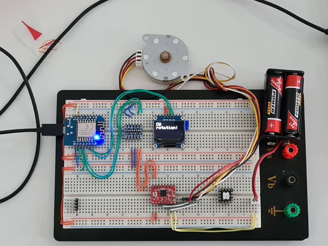
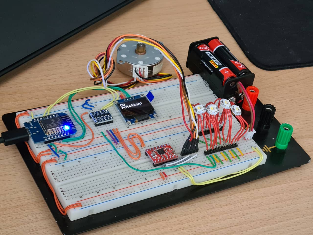
After testing the motor properly, I then replaced the flying spaghetti wires on the breadboard by some properly lengthened ones to keep a neat prototyping environment for now. The motor would later be connected by a crimped on connector, but that would have to wait until full system integration, when I would know how long my cables would have to be etc.:
//IMAGE of final breadboard so far
I decided to give the display a shot. I really liked the idea of having a small, hidden display for the full weather information (invisible from the children’s perspective). A display also always comes in handy for debug purposes, as then less focus has to be put on a Serial connection for debugging. The OLED display I had at hand had a resolution of 128x64 pixels on a diagonal of 0.96”. Teeny, tiny, cute - and most probably enough for my needs. It is connected and talked to via I2C and also 3.3V compatible - so on the 3.3V breadboard it went (with supply voltage and ground pins being connected to the 3.3V and GND rails, respectively):
//IMAGE of breadboard with screen, no data lines yet
When it came to connecting the I2C lines for data communication, I was lost for a moment: On the D1 Mini pinout diagram as provided by the manufacturer, there are no pins carrying the usual I2C names SCL and SDA at all:
//IMAGE of D1 Mini pinout here
In fact, the whole legend creates more confusion than explanation, simply stating that “wiggly line” pins are PWM/I2C/1-WIRE. Not very helpful -.-
In my quest to find the proper I2C pins, I asked the oracle (Google) and found a website stating that it would be Arduino pins 4 and 5 (or D2 and D1 in D1 mini’s terms) for SDA and SCL. I couldn’t really find any source backing that up quickly, but it also matches the master_reader example for the Wire library (which is an I2C library) found in the Arduino IDE specifically for the D1 Mini board (“Examples for LOLIN(WEMOS) D1 R2 & mini):
#define SDA_PIN 4
#define SCL_PIN 5
Looking through the legend of the D1 Mini pinout I was intrigued by the “HSPI” in there. Turns out the ESP8266 actually does have two SPI interfaces (even more, but two accessible ones). More on that here: https://blog.bachi.net/?p=10562
If you paid attention up to this point, you will have noticed that there is a alight clash in that I am already using Arduino pins 4 and 5 (D2 and D1) for talking to my stepper driver. Fortunately, this can be done via any other pin, it does not need specialized pins to do so, so I changed over my code (and breadboard) to use pins D4 and D3 (2 and 0 in Arduino terms), so as not to disturb the breadboard setup too much (D3 and D4 are right next to D1 and D2). I couldn’t really make out what the “HIGH Run, LOW Flash” part in the legend regarding pin D3 was supposed to mean:
//IMAGE of legend weirdness
In the end, testing it and changing the stepper driver code to use pins 2 and 0 worked fine though, so I stuck with it for now, keeping in mind that there is a certain weirdness there. After connecting the stepper driver to 2 and 0 I then went ahead an connected the display to D1 and D2 (5 and 4), so to the I2C bus:
//Image of breadboard with connections
Programming the Display
Software-wise, the manufacturer’s/seller’s website states:
The display can be quickly programmed using the two libraries, Adafruit GFX and Adafruit SSD1306, which also contain sample sketches.
Also, the library file they provide for download suggests that the SSD1306 library would be suitable for this display (SSD1306 probably being the display controller):
//IMAGE of library file path with “SSD1306” in name
To avoid manually installing libraries, I looked in the Arduino IDE library manager searching for “OLED” and found the aforementioned library “Adafruit SSD1306” by Adafruit, which was already installed on my computer, but not up to date. I updated it to v2.5.3 and had a look at the examples provided. There is a basic example for the 192x64 pixel display being run via I2C provided in the SSD1306 library. At first, after uploading, nothing happened. I then went back looking for the I2C address of the OLED screen module. At first I couldn’t find any info on the seller’s site. I then noticed that the seller also provided a free-of-charge ebook for the product, which I downloaded and which stated that the basic address was 0x3C instead of the 0x3D in the example. Changing over this value and changing OLED_RESET to -1 (meaning that the board does not have its own reset pin, as is true) and then uploading the code immediately made the display come to life - those 64 pixels vertical resolution are more than enough to display several lines of text in readable size!
//VIDEO of screen working
//IMAGES of text on screen
All that was left for now was to clean up the spaghetti wiring again and restore a neat breadboard:
//IMAGE of neater breadboard
Integrating Stepper and Display Control
After tidying up the breadboard, I decided to whip up a MWE using both the StepperDriver as well as the Adafruit SSD1306 library together. Sometimes the weirdest things happen when you start to cross streams, so to say, and I did not want to be caught by this later. I started by using the display example code, stripping away all the test graphics functions (as I would only display text if needed) and writing a little extra function displaying mockup temperature values:
// iMAGE of temp mockup display here
I then added a function that would indicate “CW rotation or “CCW rotation” and that would run when the motor would move in a particular direction. Note that this is all more or less for fun here, there is no explicit requirement in my design for the motor and the display to run/refresh at the same time. In the end (after removing a few unnecessary delays from the code) it all turned out fine:
//VIDEO of motor and display working together
Adding WiFi Code into the Mix
I then decided to also try integrating the code for the WiFi function. Since the D1 Mini would not query the API often at all, later (only once every 10 minutes), there should not be any problem running the WiFi API querying code together with the rest. I decided I would display the actual temperatures returned by the API for testing:
//IMAGE and/or VIDEO of returned values on OLED
It needed a bit of shuffling of variable declarations and some type casts to make everything work together, but in the end I got it working. The board will initialize, create a WiFi connection, parse the weather data after receiving it through the API and then display the parsed values on the display, intermittently also moving the motor and changing the display content:
// Video of prototype with all features integrated
End of Day
Day 5 - Some Electronics Polishing
Tuesday, again: change of plans. With the prototype pretty much finished ona breadboard, this day, I decided to first flesh out the program a little more to use the display to indicate connection status as well (as this makes debugging a little easier). First, I rearranged the code to have the display initialize first, so it could immediately be used for startup sequence debug info. Then I implemented a function to print WiFi connection info to the display instead (or rather: additionally to) of the Serial console:
//IMAGE of bootup sequence WiFI info //((or VIDEO))
Fixing Display Output
Now there’s still a problem to fix with the weather display: There is no degree symbol (“°”, circumflex), even though it somehow shows omn the page of characters possible to print. A quick internet search revealed that directly printing a char(acter) using its number from the character table might work. I tried following snippet instead of “°”: display.print((char)247); or respectively, I embedded (char(247)) into my weather output string as follows: display.println(dtNow.substring(11) + ": " + tempNow + ((char)247) + "C, " + humidityNow + "%rH," + weatherNow);.
Unfortunately, this was not successful yet, it gave me a wrong symbol, namely the “approximately equal” symbol: ≈:
//IMAGE of approx equal failure
As I had read before (an interesting piece of code history, btw), there was a problem with an off-by-one error in certain areas of the symbol table (cp437) used by the Adafruit GFX library. At some point in time, that off-by-one error was introduced accidentally and never really fixed to not break compatibility with a lot of code that had already been written:
The built-in font is based on the original IBM PC character set, known as Code Page 437 (CP437 for short). Many embedded systems still use this as it’s compact and well established.
Years ago, when originally transcribing CP437 into the GFX library, one symbol was accidentally omitted. Nothing fatal, code runs fine, but every subsequent symbol was then off by one compared to the “real” CP437 character set. By the time this was discovered, so much code had been written — projects shared online but also in fixed media like books and magazines — that fixing the bug would break every existing project that relied on those extended characters!
So the error has been left in place, on purpose, but this creates a different issue if one is adapting code from elsewhere that relies on the correct CP437 symbol values.
A compromise solution is a function that enables or disables the “real” CP437 sequence. By default this is off, the off-by-one order is used, so that all the old GFX projects in books work without modification. The correct order can be enabled with:
I remembered I had seen the “≈” symbol looking for a proper “°” symbol going through the Adafruit documentation. Lo and behold: There it was, directly next to the “°” symbol I was looking for. An image comparison of the real and the off-by-one character tables provided by Adafruit shows them side by side in the very last row:
//IMAGE of Adafruit Bug comparison
The simplest fix was to just shift over to the next character in the table by going with index 248. And indeed, after changing (char)247) to (char)248), degree symbols started to pop up left and right (with some fixes made to the unit spacing, too):
//Image of fixed degree symbols
Adding Programmable LEDs
Before committing to a fixed electronics mainboard design, I wanted to also test an implement the NeoPixel/One-Wire-LEDs - if I wanted to use them in the finished product later, I would need to provide connectors for wiring them up on the mainboard. First, I dug out the LEDs from my personal stock: They were SK6812 RGBW LEDs by Kuman that I bought a few years ago. Back then, I remembered that they were a little quirky regarding the order of color information sent, so they weren’t 100% compatible to existing libraries. I was interested to see whether compatibility had changed over the years, as these LEDs were still available on the market (and priced well at ~20€ / 100pcs.). So I soldered up six of the LEDs for testing and made myself a little test stand on the system breadboard (where I only used 3 LEDs for now - if everything worked with 3, it would certainly be okay for 6, too). At this point, I also removed the other NeoPixel clone from the breadboard, as I’d not use it anymore:
//IMAGE of 3 daisy-chained LEDs on breadboard
All LEDs are connected to power and GND separately in this test case, only the data line is carried from LED to LED (using the green, diagonal jumpers underneath). An article by Adafruit regarding best practices when using NeoPixel LEDs (which are not identical, but very similar) mentioned explicitly to remember that the data line on LEDs powered by 5V had to be 5V, too, so if a lower supply voltage was used on the microcontroller, a level shifter would have to be used for the data lines. That made sense to me and I suspected it would be the very same for my SK6812 LEDs. My level shifter on the breadboard still had two more channels available, so no problem. I wired up pin D5 (14 in Arduino terms) to a channel of the level shifter and wired its output to the data input of the first of the three daisy-chained LEDs:
//IMAGE of full breadboard with wires to level shifter and LED
Programming the LEDs
Before powering up the circuit, I looked for libraries fpr the SK6812 LED, which it seems there were a number of. I decided to try the NeoPixelBus library by author Makuna, which in comparison to the other options (especially using an ESP8266) sounded like the most advanced and feature-rich one. I installed the NeoPixelBus library v2.7.0 directly from the Arduino IDE library manager:
//IMAGE of library manager
I then opened the NeoPixelTest example sketch provided by the library. From the comments in there, it shows all kinds of connections that can be made and also how to connect the LEDs to the I2S bus, when using an ESP8266. Reading through the example code, there was stated multiple times that on ESP8266 microcontrollers, no pin could be chosen for the LED connection, but that pin GPIO3 would be used in any case which had hardware DMA support. The D1 Mini pinout states that pin RX on the breakout board was IO3, which I assumed meant GPIO3 in ESP8266 terms. I double checked using another website, which stated the same, here with explicitly mentioning GPIO3, too:
//IMAGE of another ESP8266 pinout here
I changed over my wiring to use pin RX instead of the formerly chose D5 for connecting to the level shifter and LED chain. Then, I changed the code to reflect the number of LEDs I use and the fact that I use RGBW LEDs instead of RGB LEDs (with a separate white channel). After uploading the code to the board, the LEDs came to life:
// IMAGE of LEDs doing G R B
While the code was programmed to light the LEDs up in order red-green-blue, in my case, the LEDs lit up in order green-red-blue. Going by the comments in the example code, this is to be expected and can happen when the LEDs used use a different color ordering in the data sent than standard RGB. This can easily be fixed by setting up the color order when initializing the NeoPixelBus library by changing the initializer NeoPixelBus<NeoRgbFeature, Neo800KbpsMethod> strip(PixelCount, PixelPin);. Here, the NeoRgbFeature can be changed to NeoRgbwFeature when an RGBW LED is used and also the color order can be changed to NeoGrbFeature or NeoGrbwFeature, respectively. After making that change and reuploading to the board, the pixels now lit up in the expected order red-green-blue:
//IMAGE of LEDs doing R G B
The example code is explicitly written to also test a 4th LED using the white channel, so I quickly added another one to the breadboard and changed the number of LEDs to be used to 4 again:
//IMAGE or RGBW test working great.
Since this seemed to work without problems, I decided to add the feature to the code right away to make sure there were no collisions. After copying over all necessary pieces of code and programming the LEDs to turn on when the motor was going CCW and off when it was going CW, here’s the result:
//VIDOE of LEDs not lighting up in integreated example
Adding LED code to the Code Base - Problems!
Time for debugging. I must have missed something when copying over code from the example to my integrated code. Making the LEDs turn on in the very beginning of the setup() function in red-green-blue-white actually turned them on before connecting WiFi, but all commands afterwards in the loop() function did not change the state of the LED anymore. To find out which part of the code broke the LED functionality, I added colored blinks in intervals of the main code. From what I gathered, it seemed like the display.begin() function of the Adafruit SSD1306 library broke the LED functionality. Looking through the SSD 1306 library code, I couldn’t find any signs of the library using the LED pin for something else or where a conflict might arise. Looking further and poking the code again, I noticed that is was not actually the display.begin(), but the Serial.begin() function call that broke the LED functionality. Now things started to make sense. It seemed like the Serial communication was routed through the specific hardware UART (UART0, with pin RX being RX0, so the receive pin of UART0) that I used for the LED right now. Fortunately, there was an alternative in the NeoPixelBus library using the other UART module of the ESP8266 (UART1), where if used, GPIO2 would be used for the LEDs instead of GPIO3. With GPIO2 being the transmit pin of UART1 (TXD1 in the pinout), this should get rid of the conflict.
To make the change, when initializing the strip in code, instead of NeoPixelBus<NeoGrbFeature, NeoEsp8266Dma800KbpsMethod> strip(PixelCount, PixelPin);, one would call the function by NeoPixelBus<NeoGrbFeature, NeoEsp8266Uart1800KbpsMethod> strip(PixelCount, PixelPin);, with NeoEsp8266Dma800KbpsMethod changing to NeoEsp8266Uart1800KbpsMethod and thereby switching over from using GPIO3 to using GPIO2. Now, the only thing was that I already used GPIO2, or D4 in ESP8266 terms, or 2 in Arduino terms, for the DIR pin of my stepper motor driver. Since the DIR and STEP pins of the stepper motor driver do not rely on any hardware pin features though, I could move them to other pins. To keep them next to each other for breadboardability’s sake, I moved both DIR and STEP to the other side of the D1 Mini board, using D8 and D7 (or 15 and 13 in Arduino terms) and changed my code accordingly…
…only it again did not work. In fact, this time I was not able to upload code to the board anymore at all. Hmph. Looking back at the pinout, it seemed that D8 and D7 were the receive and transmit pins of UART2 (RXD2 and TXD2), probably causing another conflict. Switching 2 pins over again, I ended up using D6 and D5 (or 14 and 12 in Arduino terms) for connecting my motor pins. Now the code would upload again without problems and the LEDs would light up as intended (on when doing CCW rotation, off when doing CW rotation):
//VIDOE or images of LEDs lighting up when wanted
More Problems
But something was fishy again, after I connected the actual motor to see whether everything was playing along nicely. Code wouldn’t upload again when everything was connected and the Serial monitor would show garbage characters being streamed in. Something was messed up. Maybe I had undone (CTRL-Z) once too far and blown up something? I didn’t know. When all of a sudden my computer crashed hard (as in: cursor is still blinking as I am writing this, but other than that, the computer reacts to nothing), it was time to take a break and take a step back.
After break and reboot, I had to go through the code in detail again, as my latest version of the code changes had not been saved when the computer crashed. I made sure that again the NeoPixelBus library was using the NeoEsp8266Uart1800KbpsMethod method (so GPIO2, or D4 was used for the LEDs) and the stepper motor driver pins were set up to use D6 and D5 (or 12 and 14 in Arduino terms). After setting it up cleanly like that, everything (WiFi + Display + Motor + LED) worked together just fine and the board was programmable still. Something before must have gone terribly wrong, but here we were now. As always, I made the breadboard neat again by flattening down my spaghetti wiring and went on:
//VIDEO of everything working together
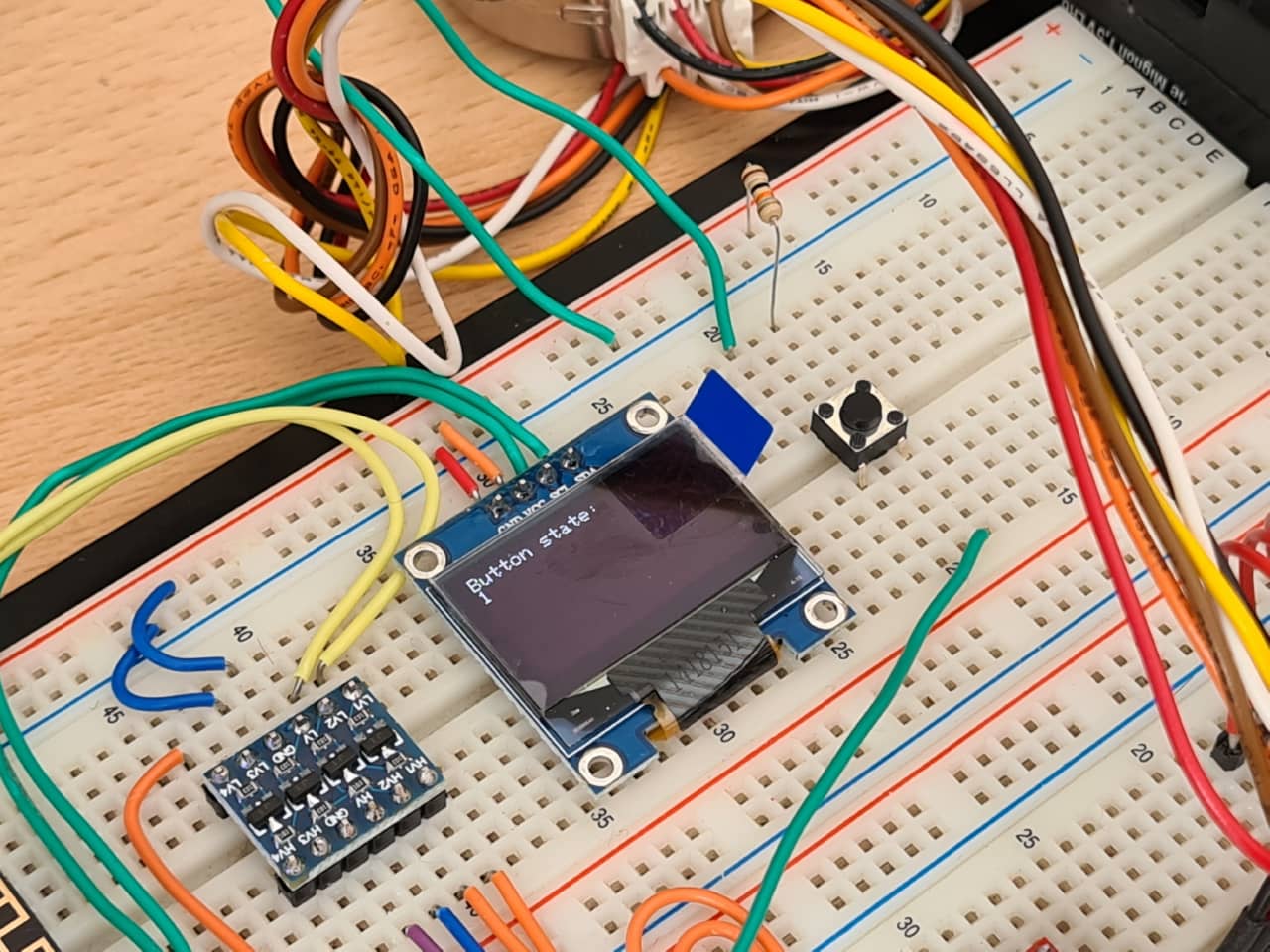
Adding a Button / Reference Switch
I then added a button to the breadboard to simulate the working of a micro switch in the final product, to be used as a reference switch for the stepper motor rotation. D3 (in Arduino terms 0) was connected to one leg of the button and then to GND via a pulldown resistor of 10kOhms. The other leg of the button was connected to 3.3V. A small function was written to read the state of the button (HIGH/1 or LOW/0) for 5000 milliseconds and print the state to the display. After a few failed tries of getting the display to display something (I forgot to initialize the font size etc.), I finally had the display display the button state of D3:
void drawButtonState(int duration){
  int start = millis();
  display.setTextSize(1);      // Normal 1:1 pixel scale
  display.setTextColor(SSD1306_WHITE); // Draw white text
  display.setCursor(0, 0);     // Start at top-left corner
  display.cp437(true);         // Use full 256 char 'Code Page 437' font
  while((millis()-start) < duration){
    display.clearDisplay();
    display.setCursor(0, 0);     // Start at top-left corner
    display.println("Button state:");
    display.print(digitalRead(BUTTON));
    display.display();
  }
}
Unfortunately, the value read was stuck at HIGH/1, even though the pin was connected to GND through a pulldown resistor. Pressing the button did not change the value read at all. Reversing the logic and connecting the pin to 3.3V using a pullup resistor of 10kOhms, connecting it to GND when the button was pressed, worked just fine though. Digging through the manual of the D1 Mini board, it was stated that the GPIO pins 0-15 did have - as many Arduinos - internal pullup resistors that could be activated in code (pin GPIO16 actually has an internal pulldown resistor). I changed the pinMode function call for setup of the button pin to be INPUT_PULLUP instead of INPUT and removed the discrete resistor from the breadboard (instead using the internal pullup connection to 3.3V when the button was not pressed):
//IMAGE of breadboard without discrete button pullup
After flattening my breadboard layout again, I programmed the stepper motor to once, in the beginning, run CCW until the button was pressed - akin to how it would be programmed later when the stepper would do a reference drive until it hits the microswitch to find its zero position:
//VIDEO of fake reference drive
Starting the Electronics Mainboard Design
After implementing all the desired functions, I started working on the mainboard electronics design. I started out by creating a new design in KiCad 6.0. After opening the schematic, I went to Add A Symbol and searched for “D1 Mini”. I got super lucky and there already was a component with footprint for the WEMOS D1 Mini microcontroller board:
//IMAGE of WEMOS D1 Mini in symbol library
Nice! I added the symbol to my schematic. With the center piece of the circuit set, I looked for further components. There was no prepared component for the 128x64 pixel SSD1306 OLED display directly in KiCad or the imported libraries so far, but I quickly found an SSD1306 module on Github. At this point, my son started crying in his slpee, so I called it a day :)
End of Day
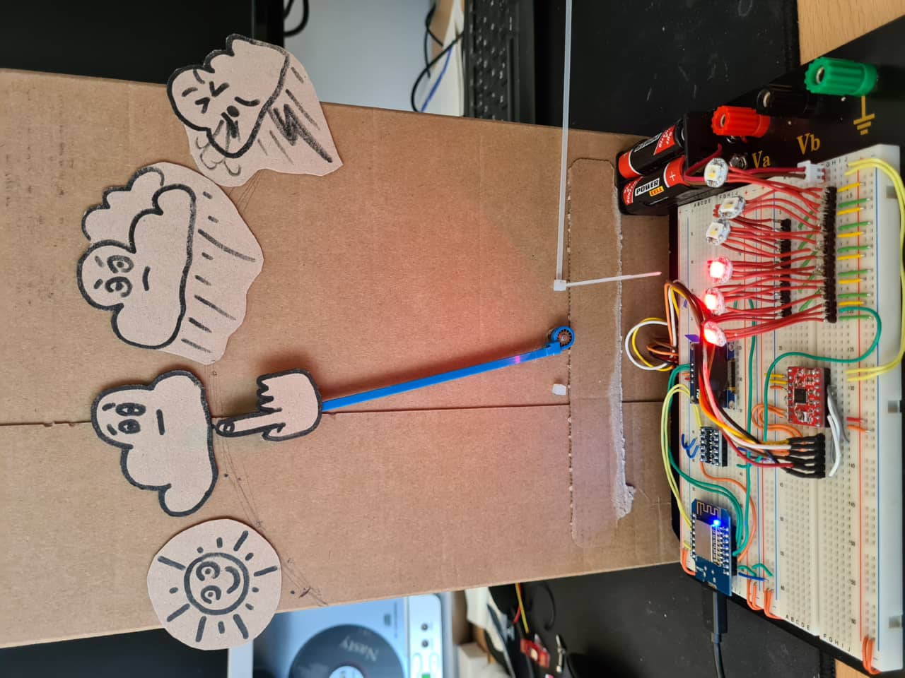
Day 6 - Mockup Time
On day 6 I started with making a cardboard mockup before global class, mostly for getting the assignments done. It also helped a lot in getting the plans finalized for the coming days of production:
After global class, it was family time again and so I only managed to read up a bit more on KiCad 6.0 libraries - a topic that still baffles me with its complexity :)
Day 7 - Turning Mockup to Reality
With the mockup in hand, I took a long, hard look at whether it would tick all the boxes for the final project assignment and for myself. This Thursday was one of the last days to reasonably order in anything that had been missed out (as Monday with Pentacost is a public holiday in Germany and anything coming in on Tuesday would be too late to properly integrate). I noticed that while I had run my motors on (weak) 4xAA batteries for all the test (running at around 5.5V only), I hadn’t really tried powering the device from USB exclusively (using a USB power brick, not a computer USB port)
Day 8 - Other things to do
Day 9 - Finally Making Things!
On day 9 (phew, time was flying!), I finally got around to making things. First things first, I started to properly take care of the electronics schematic in KiCad.
Fixing KiCad Libraries
I was still missing libraries for a few components on my board. First things first: I had found a libary for the SSD1306 OLED module (see above), but due to being a little outdated, it imported into KiCad as a Legacy library. The symbol in the symbol library and the footprint in the footprint library were not connected, so I set out to edit the symbol to point at the proper footprint.
//IMAGE of missing footprint refernenc
Unfortunately, being a Legacy library, editing using the Symbol editor was not possible. First, I had to migrate the library, which really only was a push of one button in the Library Manager. After doing so, I could now edit the S´symbol and point the associated footprint at the SSD1306 OLED module’s footprint.
//IMAGE of footprint updated
After getting the OLED module out of the way, I quickly made myself a library for the little 4-channel Level Converter module. I started by creating a new symbol library for the module, then adding a symbiol to it. The symbol was a rectangle with low-voltage pins being placed on the left, high voltage pins on the right and supply and ground pins being placed at the top and bottom edges of the rectangle.
//IMAGE of converter module symbol
I chose the pin numbers according to the pin order such modules (and ICs, mainly) are usually numbered in: the lower left pin is 1, then pins are counted counter clockwise. The LV-HV pins were labled as Bidirectional, while the other pins were labeled as Power Input pins. After saving, I added the freshly generated module symbol to my schematic:
//IMAGE of schematic with new sambol
Adding Logical Connections
Finishing up the schematic, I noticed that a) I still had a channel in the converter module left over and b) I had forgotten to implement the enable/sleep functionality of the stepper driver to turn off motor power when not needed! I quickly wanted to add that connection, but I also had to test it first.
First, I went back to my stepper driver MWE, which only tested motor funtionality. In there, since a lot of things had changed meanwhile during integration, I first changed the DIR and STEP pins to the final ones of the finished mockup (with all functions integrated). I then looked up which pins were left on the D1 Mini board and decided for D0 (16 in Arduino terms) for the enable function. I then added pin 16 into the code as the SLEEP pin and changed the code (as stated in the commented example) as necessary to use the ENABLE instead of the SLEEP input of the A4988 driver.
At first, the enable functions did not work and I was kind of stumped. After quite some back and forth, I finally realized that I had forgotten to actually call the enable() and disable() functions. D’uh! After making the necessary changes, the code worked just fine and the motor would disable between forecasts so as to not use as much energy.
I then also added a second button into the mix and connected it exactly as the reference switch, but going to pin D7 (with internal pullup enabled). This one worked absolutely fine, too, only running the animated forecast when actually pressing the butto to request it.
Adding Virtual Connections
With all these parts added to my schematic now, it was time to add connectors for the wires. The way of handling off-board components in KiCad is a bit new to me, so I first saved the design under a different name so as not to mess with the original too much. I then went on to search for how such things are usually handled and found a very interesting link talking about the “Use of “Virtual” Symbols and Normal Wires”:
Use of “Virtual” Symbols and Normal Wires
KiCad has a feature for excluding symbols placed in the schematic from the PCB and the BOM. This is done by prefixing the reference designator of such a symbol with “#”. This is the same feature that is used for power symbols, pictograms and logos found in the official library. The text tool and graphical line/polygon tool can be used to extend these drawings further.
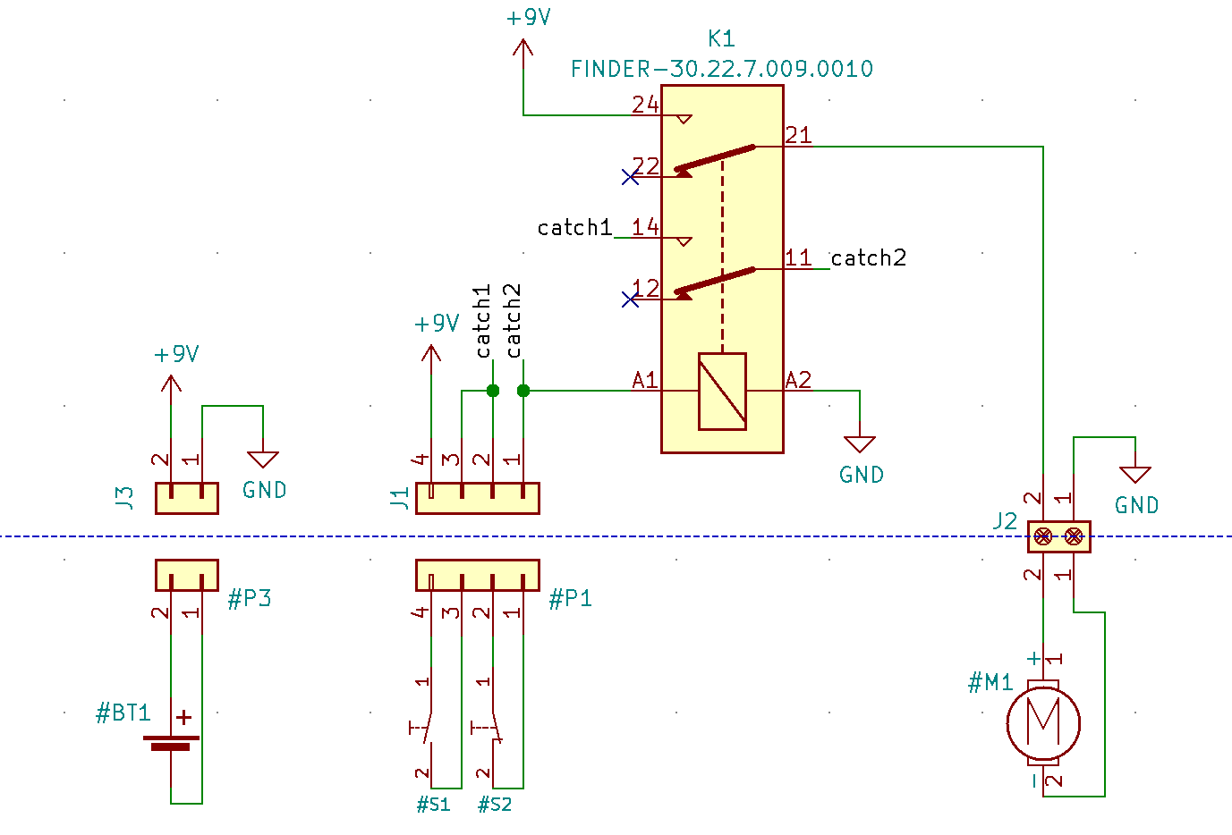
This was pretty much exactly what I was looking for for my schematic overview. After adding all the connectors and their female counterparts, wiring everything up, preceding the virtual components with a # and rearranging the whole shematic like a maniac, I arrived at following result:
//IMAGE of finished schematic with separation of offboard components
Nice. To me, that looked tidy enough to call this part of the documentation finished… if the pcb part actually worked. After (automatically) annotating all the components, adding numbers to the symbol names, I went to the PCB editor and did “Upgrade PCB with changes made to the schematic”. Most footprints were placed on the PCB layout, though one was missing and threw an error: Brd2, the logic level converter module that I had set up a library myself for. And forgotten to add a footprint… Well. off to the footprint.
Using the footprint editor, I created a new footprint library for the part (with a .pretty extension) and in there added a new footprint. Since this was a simple, breadboardable module with 2x6 pins, I had no problems placing those two rows of 6 pins in the appropriate layout of the 0.1” grid. After saving the footprint, I only needed to attach it to my symbols of choice, go back to the PCB editor and update the changes again. After doing so, the new board’s footprint appeared as well:
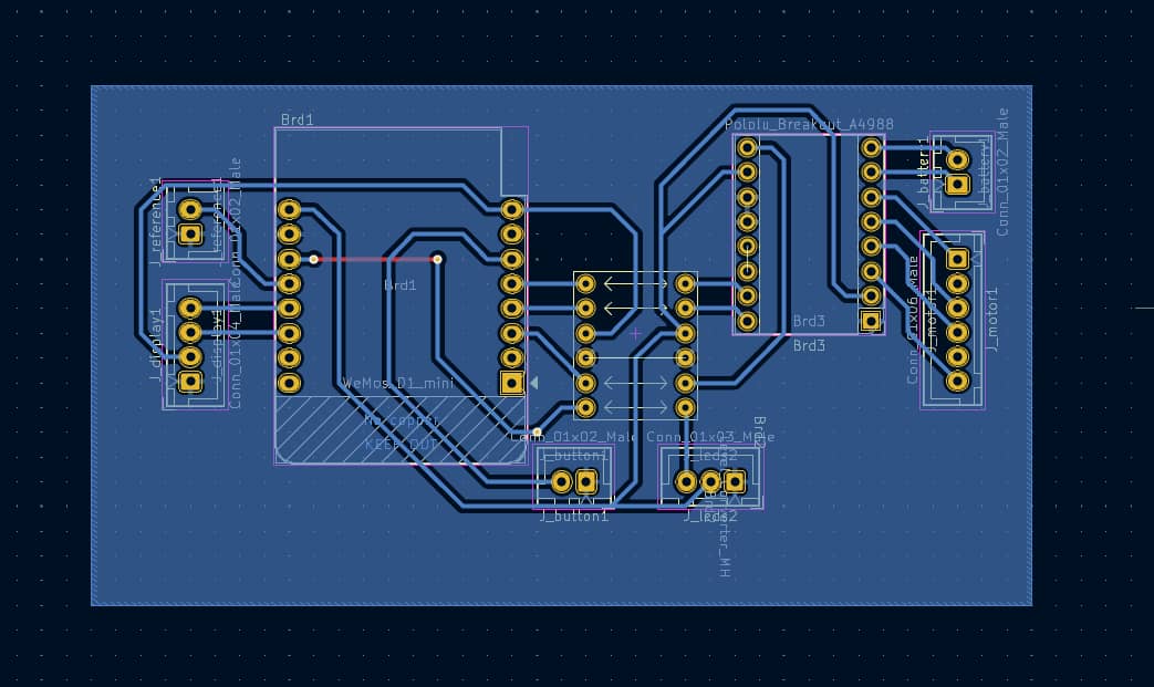
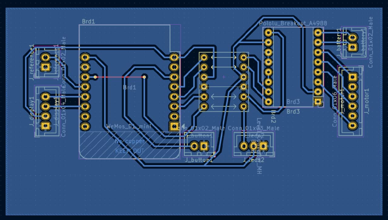
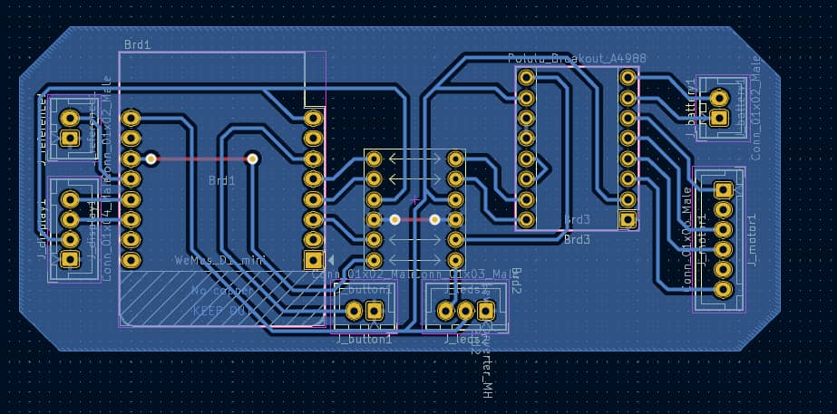
//IMAGE of all components on PCB
Now the fun of routing… I spent a good while laying out the board somewhat neatly to avoid double-sided design as much as possible (no wores crossing etc.). I also tried swapping some pins to make doing so easier, but this tended to end with the breadboard prototype not working anymore. The ESP8266 is a bit finicky in its use of the differernt UARTs and there still seems to be a pin that should better not be used. In the end, I reverted to the design I started out with and ate whatever wire bridges (/0-Ohm bridges) I’d have to place. No biggie. Not worth the hassle just for a slightly tidier board.
//IMAGE of finished board
Day 12 - We’re sinking! :)
The long weekend unfortunately did not bring as much progress as expected. Instead, with the weather in Germany being quite stormy and rainy, I had to deal with two water break-ins in our newly aquired house - both garage and basement were affected and so I had to deal a lot with reshuffling things, drying things and fixing leaks. On Day 12, I finally could get my headspace clear again for FabAcademy: On it goes!
The PCB design had not been fully finished yet, so I decided to do what Neil always emphasises: triage. No fanciness could be expected anymore if I wanted to finish until Wednesday June 8th (even though my presentation was scheduled for 15th, I wanted to try and get it done nonetheless). I still needed to:
- design-lock the PCB
- make the PCB
- populate the PCB
- transfer the sketched designs to Inkscape
- prepare cut files in Visicut
- cut the designs from plywood
- prepare a 3d-print design
- 3d-print the design
- prepare the cabling for daughterboards
- wire up the system
- test the system
- film the hero video
- edit the hero video
- prepare the presentation poster
- polish the documentation
That was at least 15 work packages (plus a little here and there) for ~36 hours remaining, including sleep twice. So basically ~24 hours of work time remaining. I was looking at about one hour per work package. We’d have to do this 24-style.
T minus 39. Hours. :) Inkscape Vector Designs
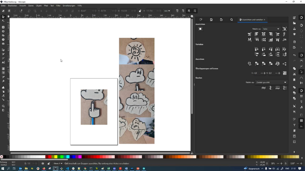
I decided to start with the Inkscape designs. I couldn’t really start the 3d-print design yet, as I wasn’t fully aware of my bounding box dimensions yet. Since I had access to a 3d-printer at home, that was not problematic, since I did not have to be in the FabLab to print. I fired up Inkscape and loaded my sketches into it. I wasn’t worried about scale yet, but I still tried to keep all them at the roughly same scale.
I started out by photographing and loading all sketches from my mockup into Inkscape as background images:
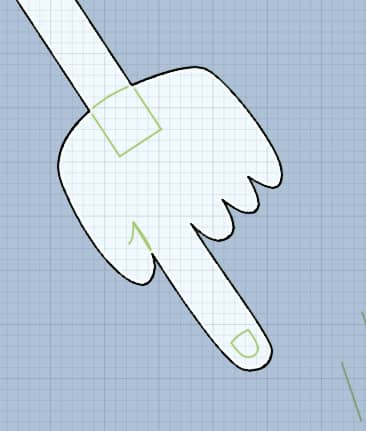
I then started with the hand. Using Bezier curves I approximated the shape…
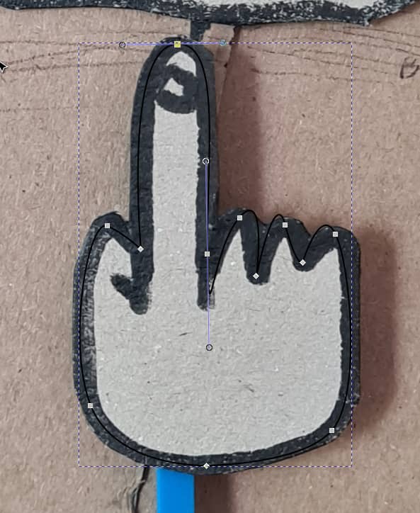
… then fattened the contour to what was there in the sketch…
… and made some refinements with the stroke color opacity lowered, so I could see through the lines:
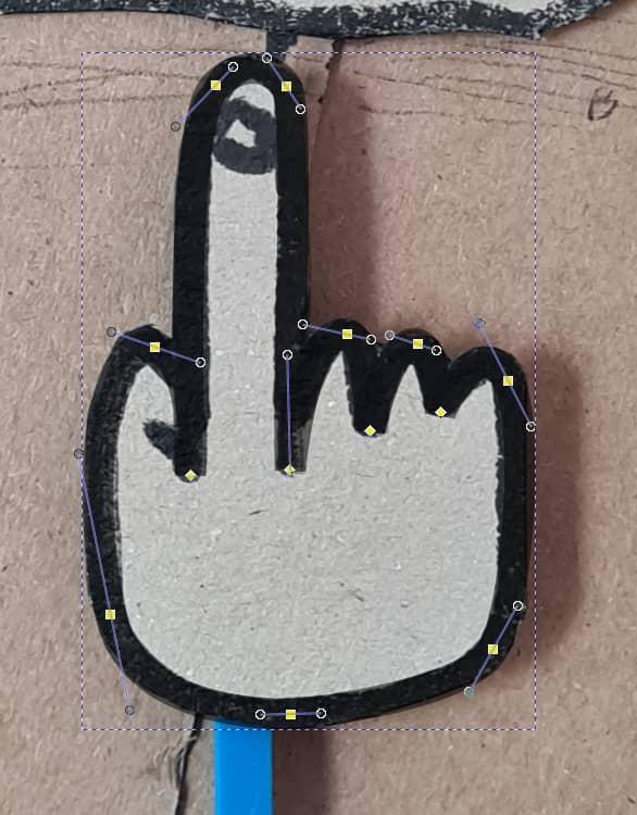
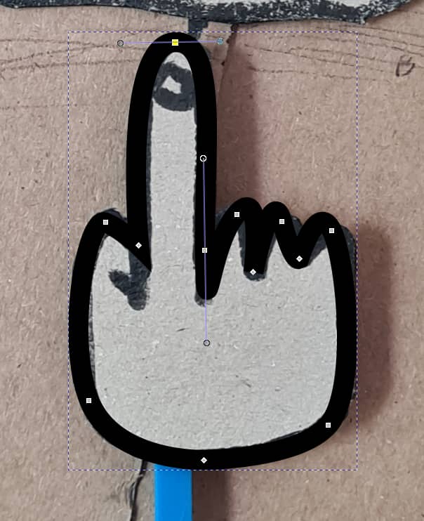
After finishing and isolating the hand vector, I noticed that there were very harsh, square connections in the path itself:
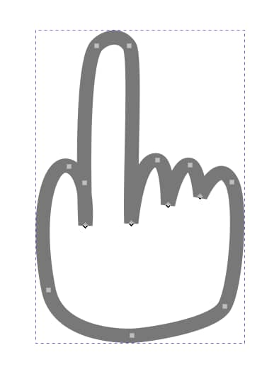
In the “Fill and Contour” tab, I changed the vector contours to using rounded connections…
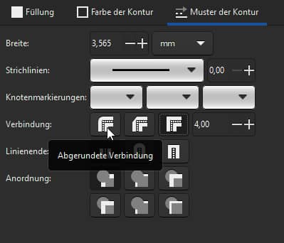
… making the nasty square joints go away:

I then added the nail and the thumb crease to the vector…

… and slightly refined the shape more and re-upped the opacity on the contour stroke:

With the hand finished, it was time to tackle the sun:
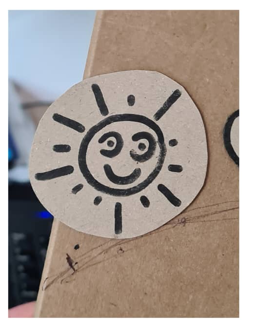
Again, I started by tracing with Beziers…
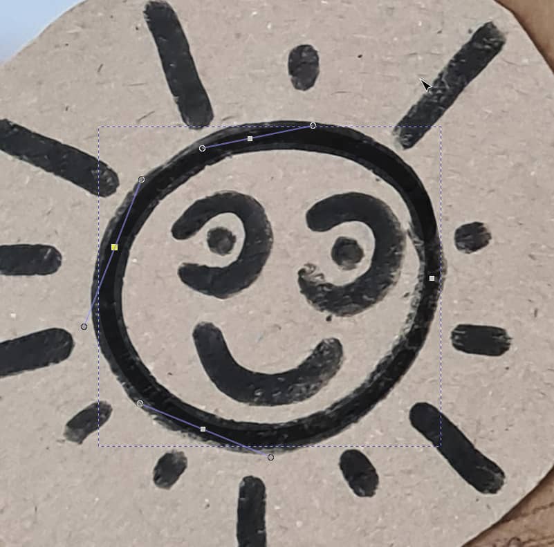
… doing the outline first, …

… then the eyes …

… and finally the pupils:

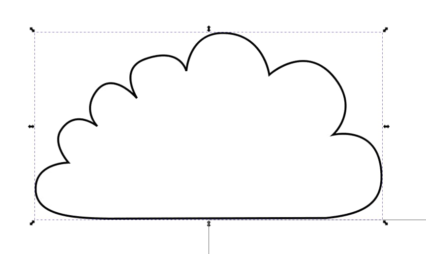
Next up: sad cloud:

Profile first, …

… then I added the eyes and added some changes from the sketch…
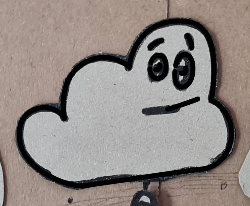
… ending at the following cloud vector:

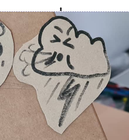
Now it was time to do angry rain cloud:
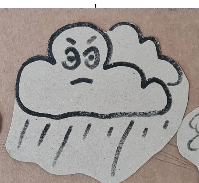
I quickly whipped up the sketch as before (copying over and reshaping eyes for consistancy, too):

Since I wasn’t happy with the rainfall coming out of the cloud though, I added some more rain and used the align …
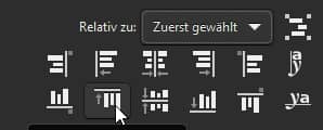
… and distribute tools…
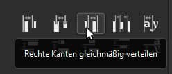
… to easily get some nicely aligned and distributed rainr ays:

Last but not least: blowing storm:
First tracing the outline…

… then adding a face…

… and some wind:

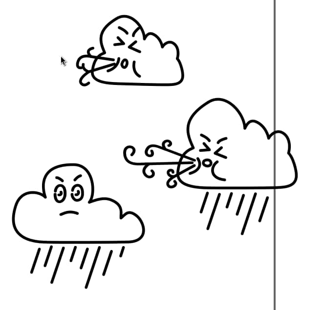
I felt the storm was quite out of place, so I copied it next to the rain cloud and made some changes to make them stylistically more alike:
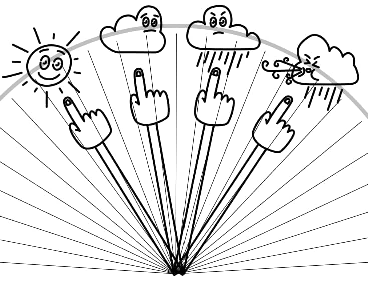
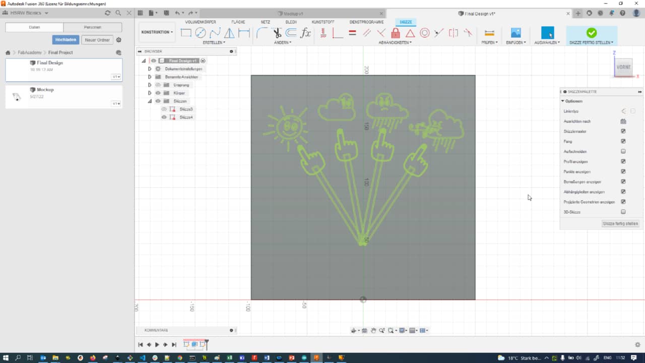
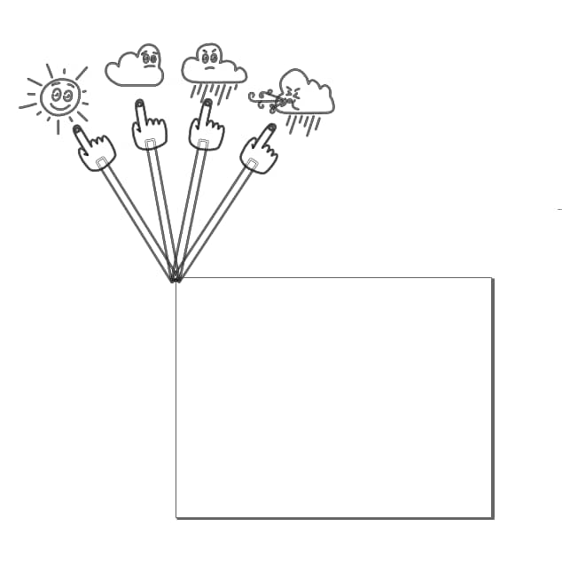
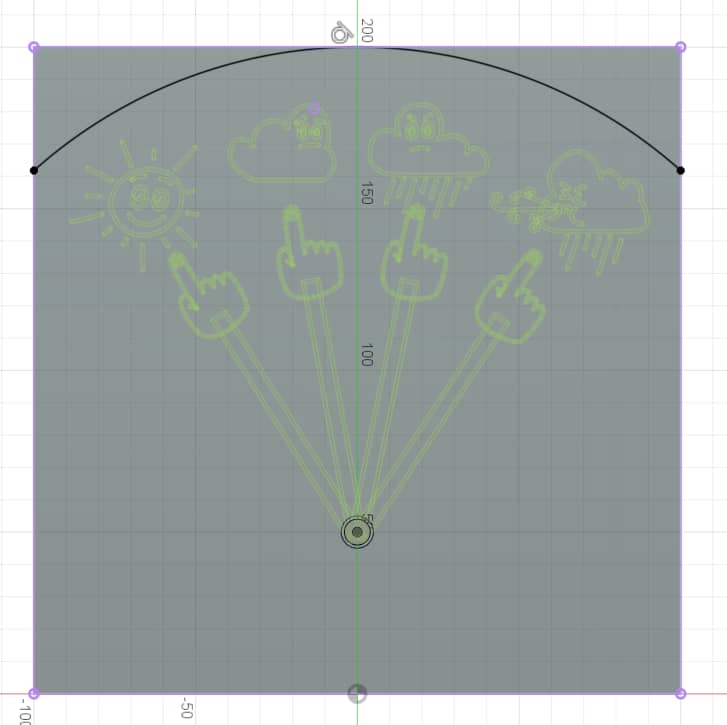
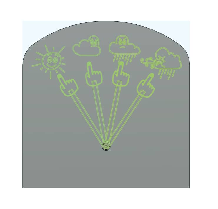
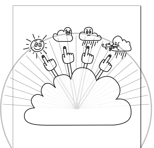
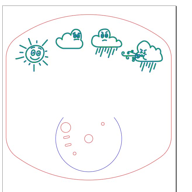
With all symbols done, I made a mockup of the final design as a vector…

… and then also added the possible motor positions (knowing the stepper motor’s step angle) to distribute the symbols properly:
Finalizing the Physical Design in Fusion 360
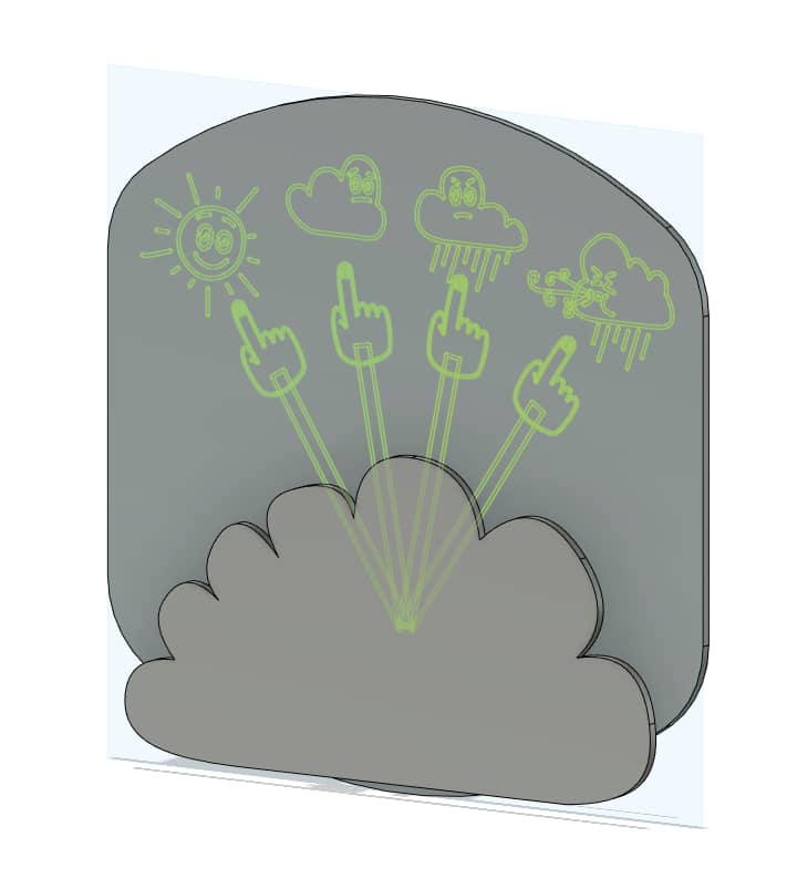
I began the Fusion 360 design process by adding the sketch of my dial:
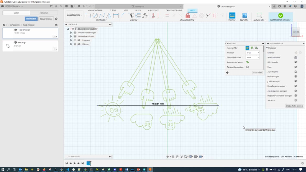
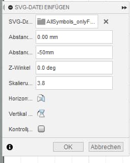
Unfortunately, it came out at the wrong size. I remembered that there had been some unit mismatch between Inkscape anf Fusion 360 SVG’s and that imported SVG’s needed to be scaled on import. I measured the size as imported without scaling an the size in Inkscape and calculated the scaling factor:
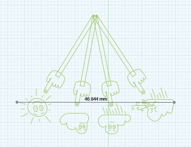
The correct scaling factor for the Inkscape SVG’s imported into Fusion 360 was 3.8:
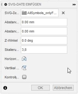
Using this factor of 3.8, the sketch was imported at its proper size:
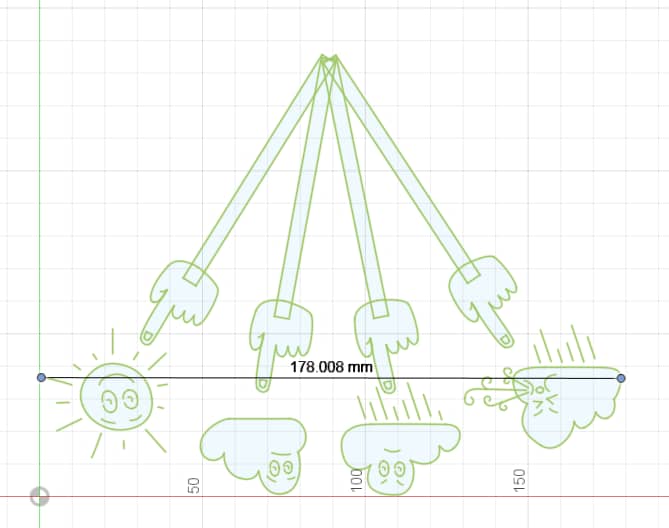
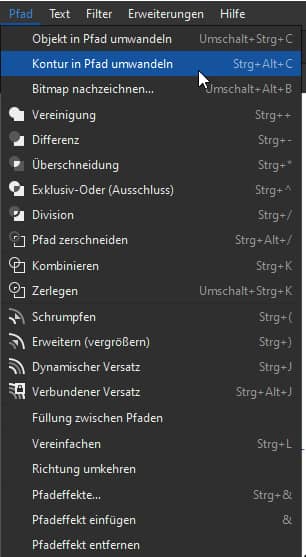
Now there was another problem: The imported vecotr were merely outlines, not actual strokes:
This was due to them actually being strokes in Inkscape with a stroke width. To actually make the strokes with two liens in Fusion 360, the vector paths needed to be modified in Inkscape by using the Convert Contour to Path function:
After converting contours to path, single, overlapping paths as shown here could also be fixed by merging them (using the union tool):

I also did a test cut of a desing with the laser cutter (shown here during setup in Visicut) to make sure everything would work as intended later. It did:
Knowing that, I added a baseplate behind my dial sketch:
To make placement easier, I also added the dial sketch again. I wanted the rotational center of the dial indicator arm to be 50 mm high on my baseplate, but it did not match up:
This was because when importing into Fusion 360, the upper left corner of the page in Inkscape is considered the root of the SVG, so I moved the parts in Inkscape to be centered around that top left corner:
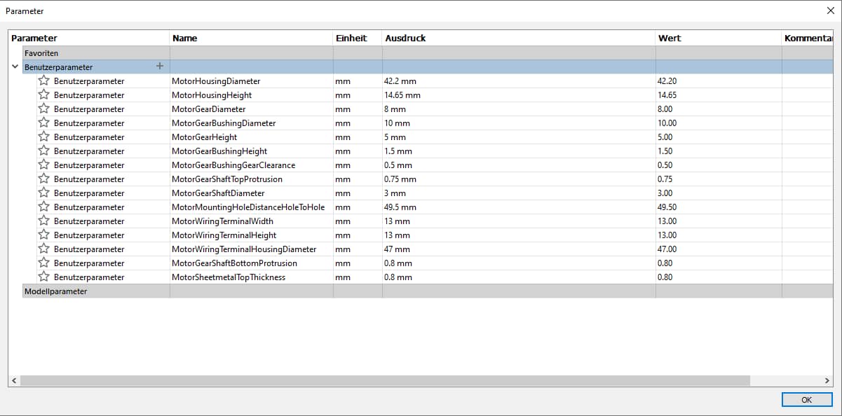
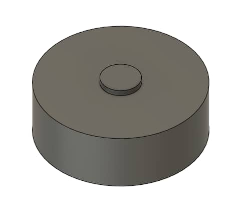
I then started modelling the stepper motor I would use in my project so I could properly design around it. Armed with calipers I measured following parameters that were used to parametrically generate the motor (in the end, there were a few more even):
I started out with the very simple housing shape,…
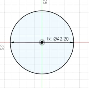
… extruded it into a cylinder…

… and also extruded the bushing of the shaft:
I then went a little crazy with constraints and measurements to get the weird mounting flange shape right:
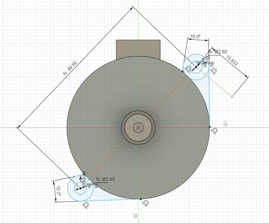
I then added the outout shaft gear as a cylinder (no gear modeled, only a snippet visible here):
I did not want to keep the baseplate square, so I added an arc to the top of the baseplate,…
… extruded away the outside material and filleted the sharp corners:
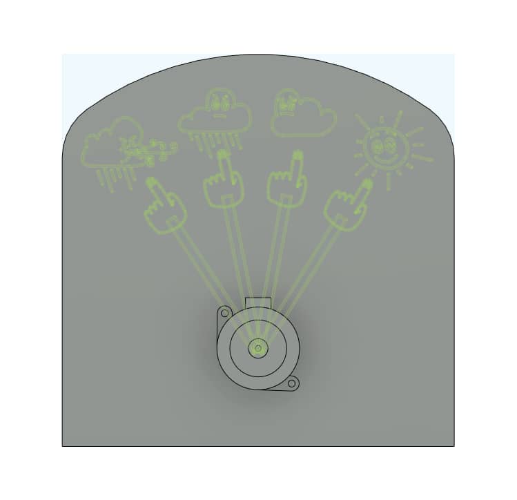
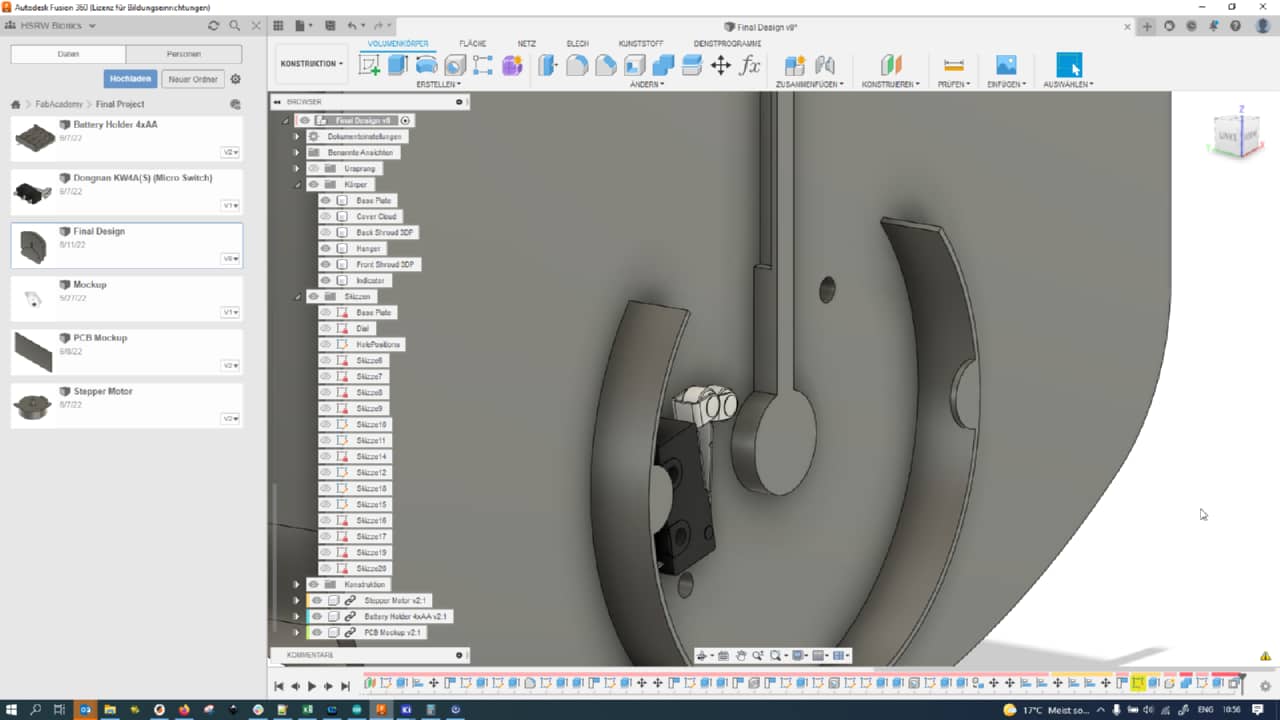
I then placed the motor part where it would sit later, in the rotational center of the dial indicator arm:
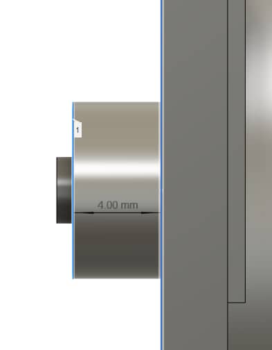
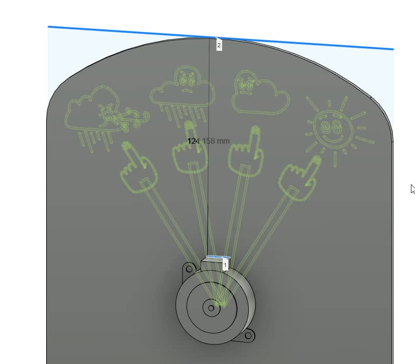
Using the measurement tool I quickly checked how much space would remain to the sides…
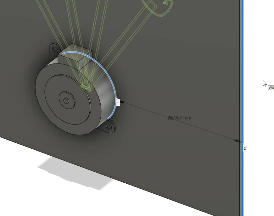
… and the top of the motor, to add all the other parts of my machine:
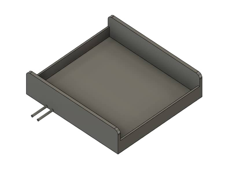
I then went ahead and modeled the 4xAA battery holder model I had at hand (they often differ slightly by the placement of their screw holes). I whipped up the basic shape, with some indicated wires,…
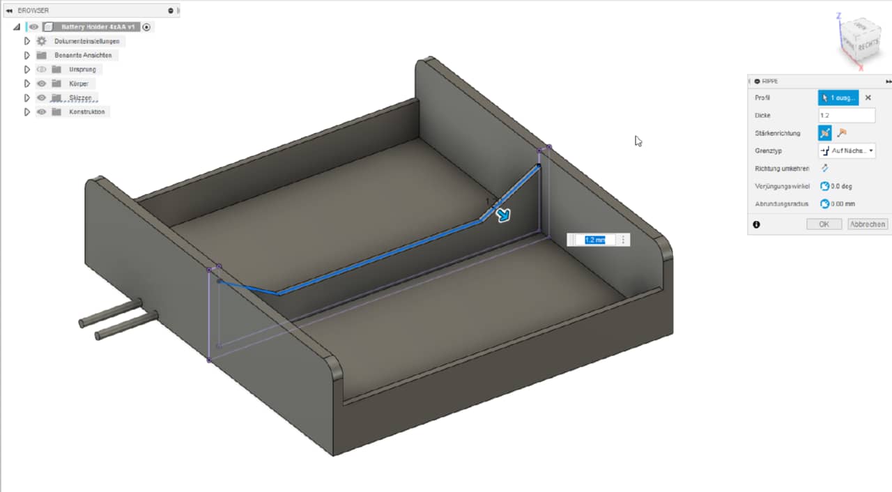
… then added some ribs…
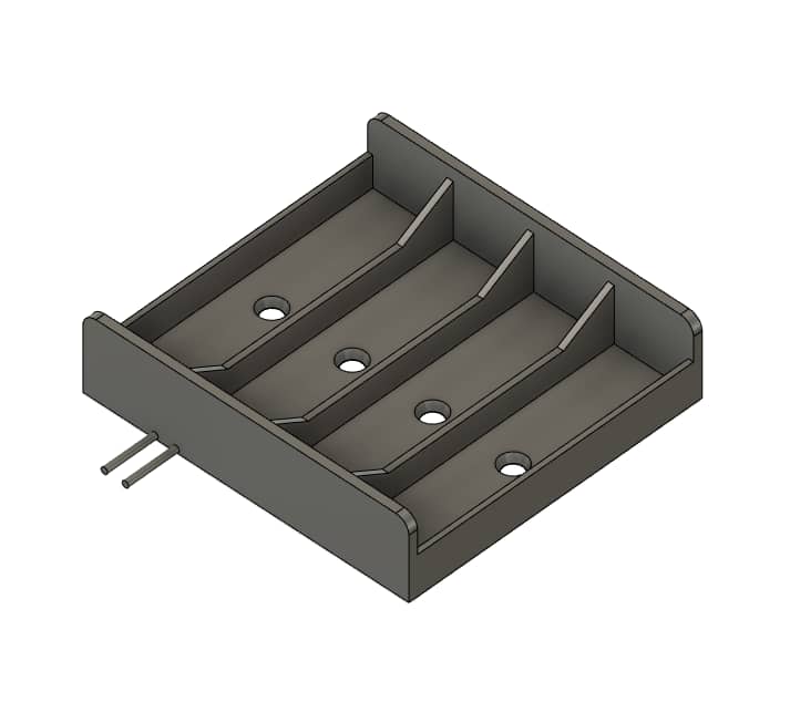
… and finally marked out the proper places for the mounting holes,…
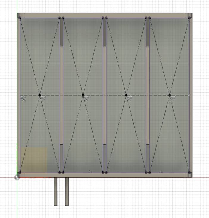
… which were drilled out using the Holetool:
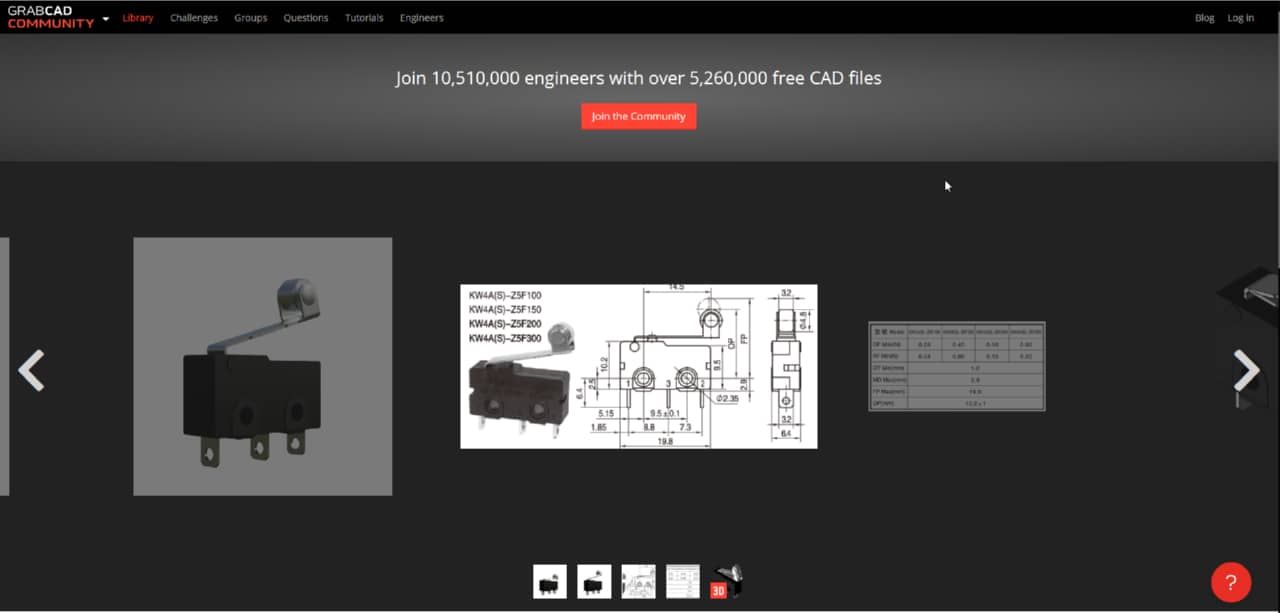
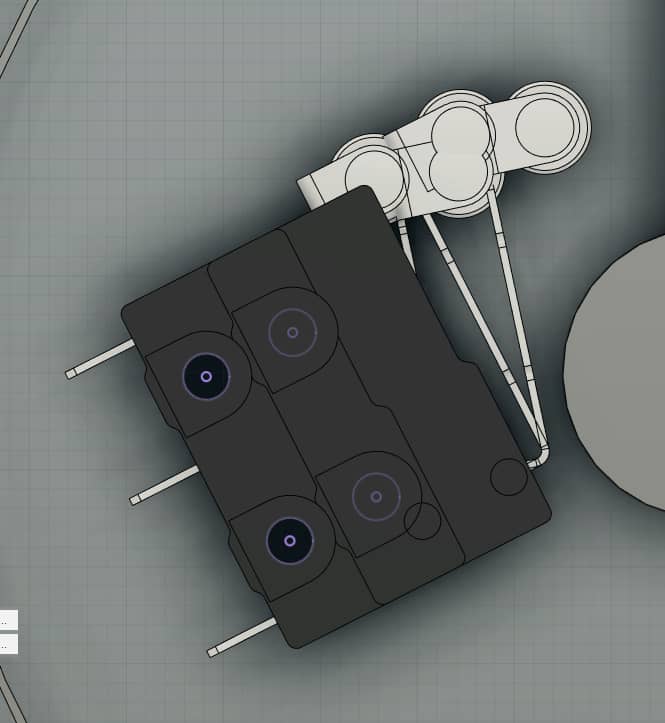
For the microswitches, I found an exactly fitting model on GrabCAD, which I grabbed. No reinventing the wheel today… :). Here it is:
I then noticed that I would need something to cover up the motor and reference micro switch in the front. In Inkscape, I came up with a large cloud hovering in front of the baseplate:
After importing it into Fusion 360 and extruding the shape, here is what I ended up with:
And here is the back side of the mockup, with a side shroud to keep everything nice and tidy from the outside:
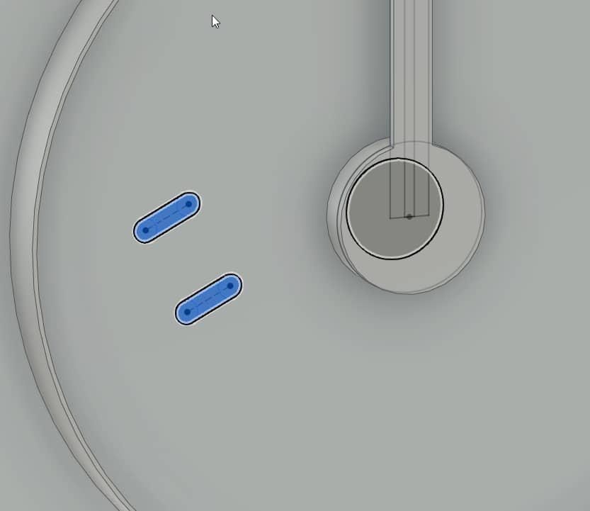
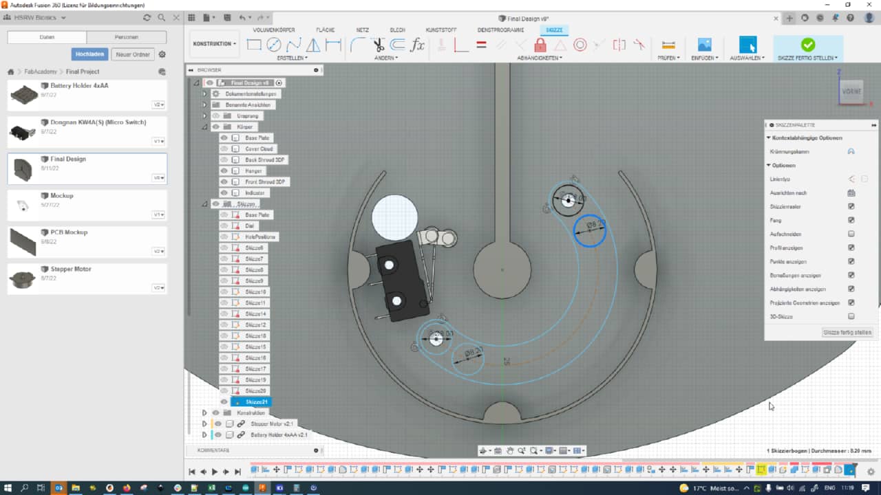
To make the reference microswitch for the indicator arm adjustable, I copied the microswitch component and placed one copy at the beginning, one at the end of the adjustment range;
I then projected the mounting holes of either of them onto a new sketch and joined the projected holes with a slot:
I then also added a large hole to feed the cable (with JST connector crimped on) of the reference switch through to the backside:
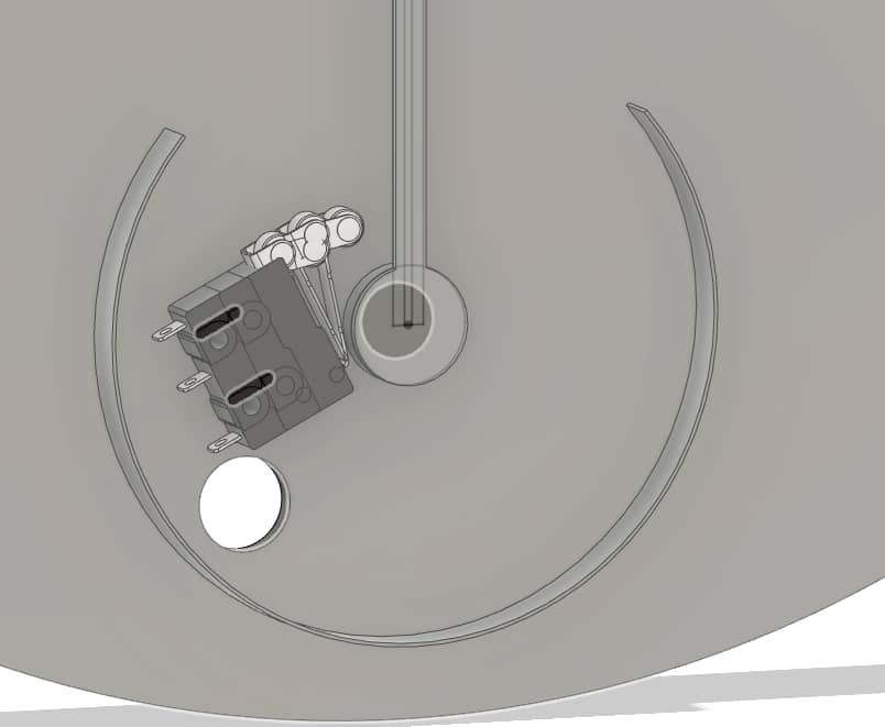
Here is another backside shot of the mockup so far:
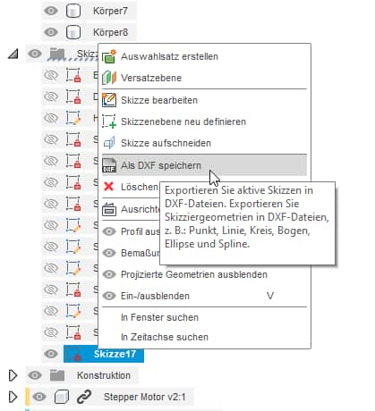
I then went ahead and projected the baseplate geometry (with all its holes and cutouts) onto a new sketch…
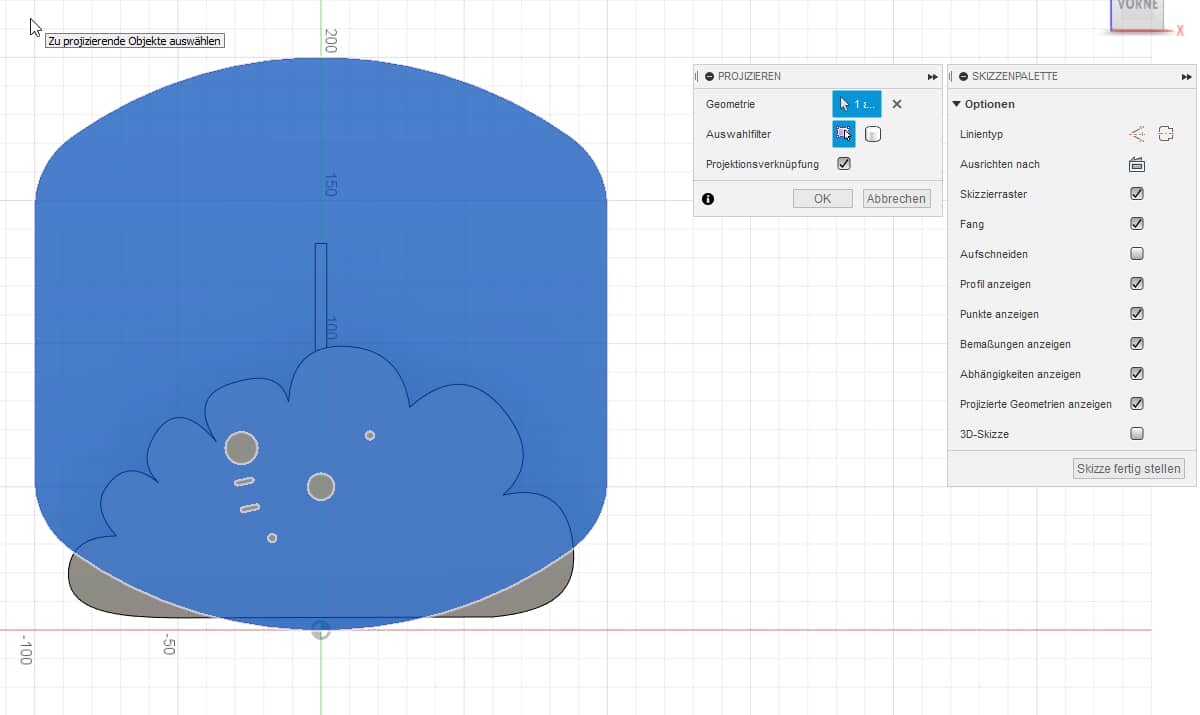
… and exported said sketch as DXF for laser cutting.
Making Stuff With Lazors
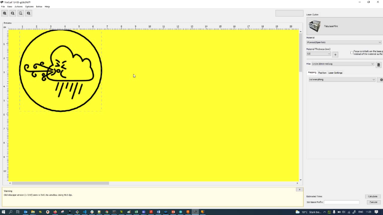
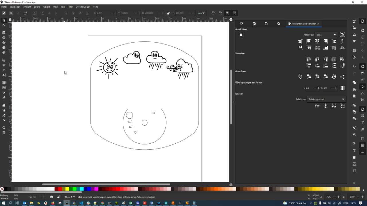
The DXF from Fusion 360 as imported inInkscape looked as follows:
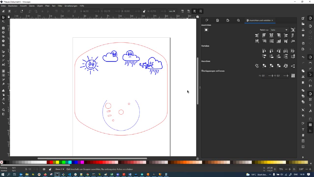
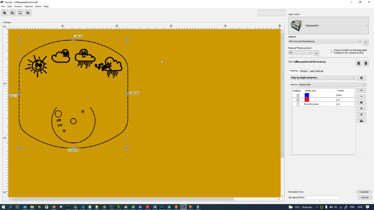
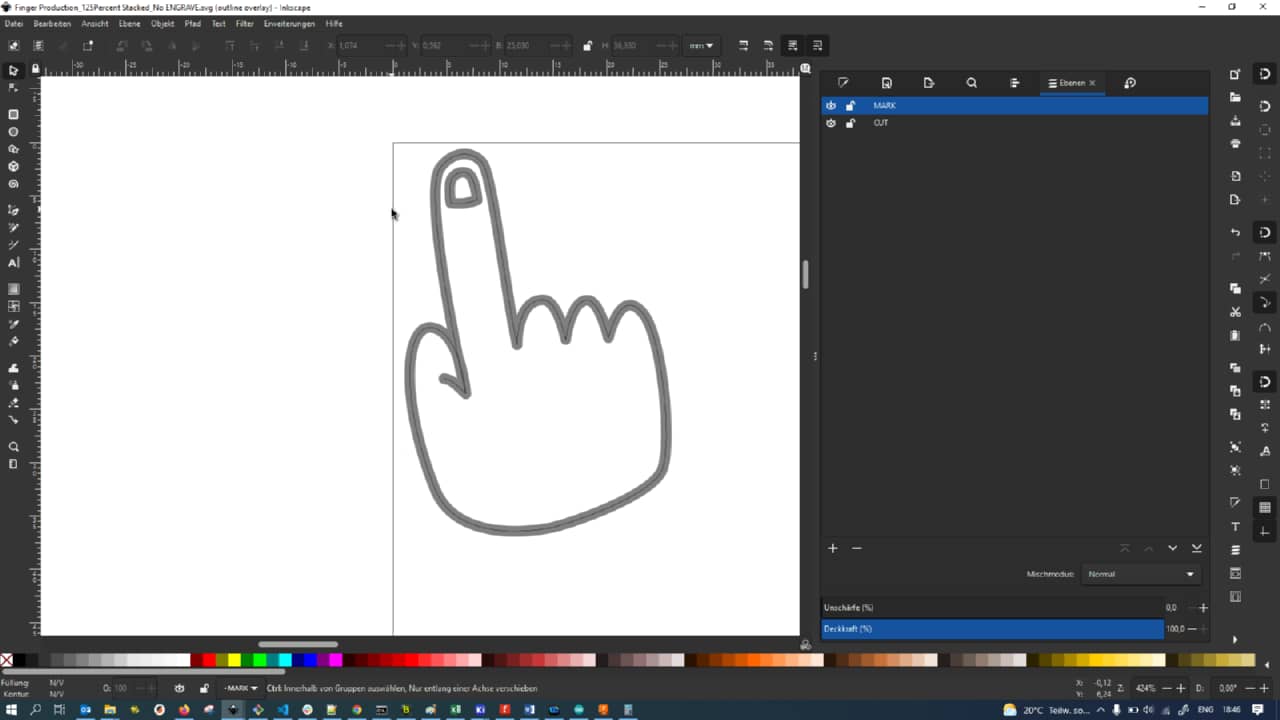
I first used different stroke colors to distinguish between cut (red) and mark (blue) lines:
When imported into VisiCut, one can setup different process parameters by stroke color (e.g. mark and cut here)
After exporting laser code (Gcode) from VisiCut, I used Universal Gcode Platform to stream to our Laser Cutter:
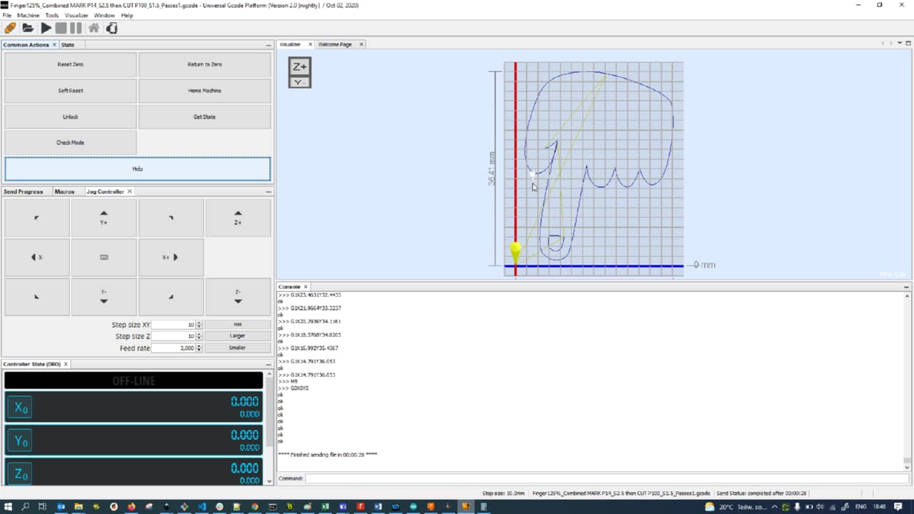
The hand, too, was a rather complicated combination of mark (for nail and thumb crease) and cut processes:
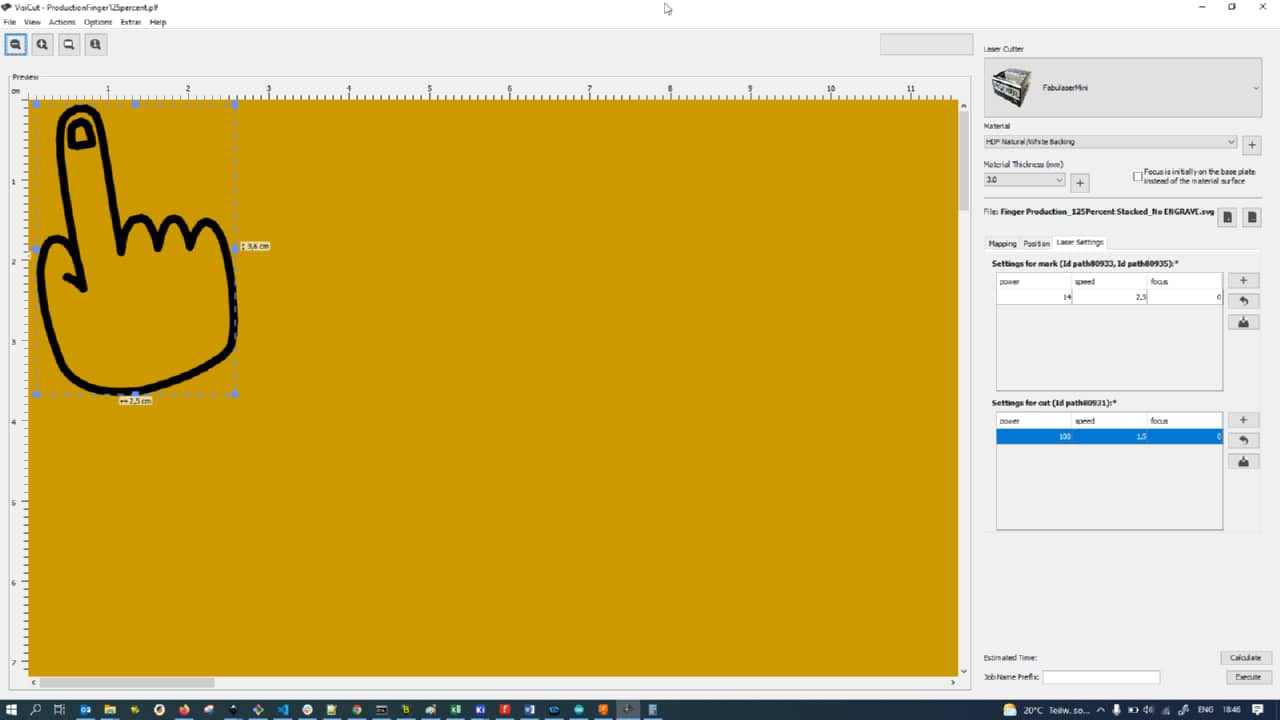
Here are the parameters I generally used for the 3 mm HDF (high density fiber) boar I used:
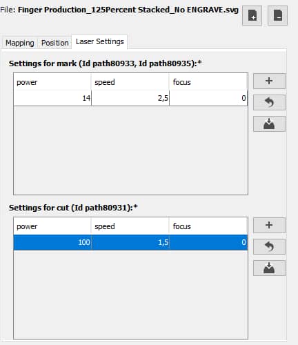
When it comes to laser cutting, a decision always has to be made whether the actual contoured line should be marked/cut or just the center vector line. In the case of the hand, I settled with just an outline cut in the end:
To actually darken the makred symbols a little, I also added green fill to the shapes I wanted to be engraved later (in this case: marked and engraved):
The cover cloud was also lasered direcly from the Inkscape source files:
To attach the cover cloud to the part later, I made a simple shroud to keep it at a distacne from the baseplate and the indicator arm:
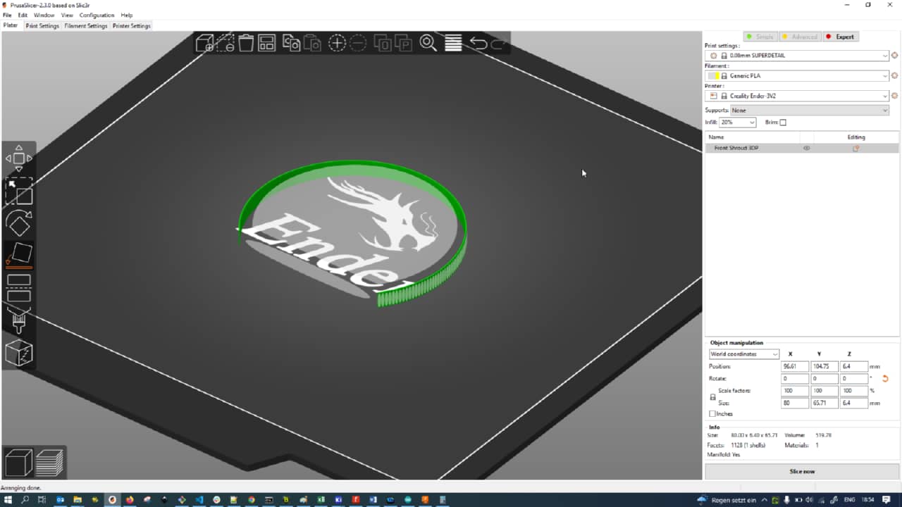
I then went ahead and printed it at a very coarse resolution (which usually still looks very clean):
Making the Mainboard - Electronics Manufacturing
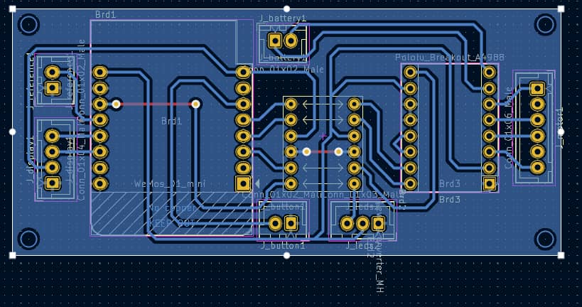
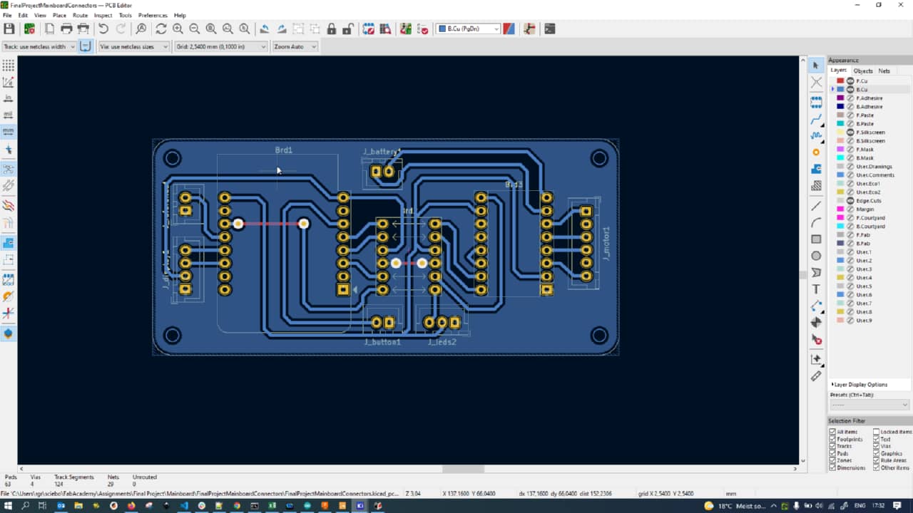
I restarted the PCB routing process with a rough verison of proper placement (with one or two jumper wires needed):
I iterated,…
… added corners…
… and refined:
I then looked up the proper measurements for an M2 passthrough hole…
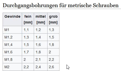
… and added mounting holes to the corners of the PCB:
I then also rounded over the edges of the PCB using arc segments in the Edge Cuts layer in KiCad:
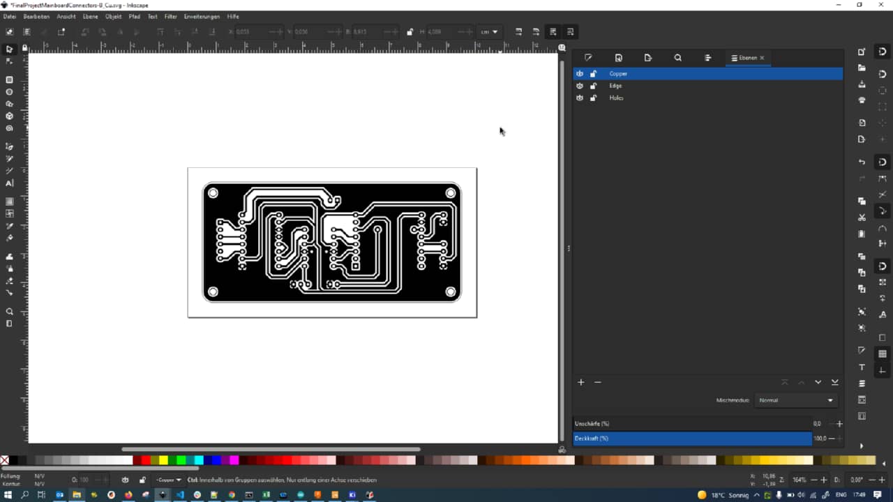
After finishing the design so far, I exported Copper, Silkscreen and Edge Cuts as vector files:
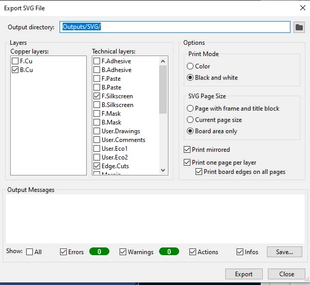
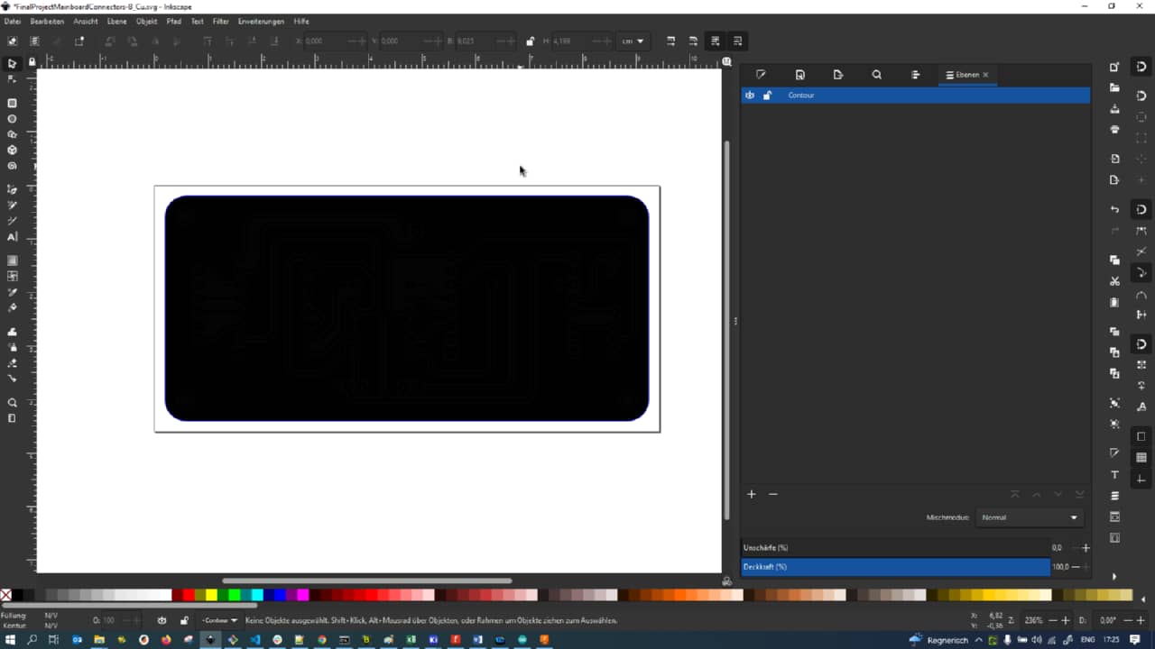
When opened in Inkscape, the rounded edges from single segments proved problematic: each arc was separate and the complete outline needed to be reassembled manually to avoid duplicate nodes:
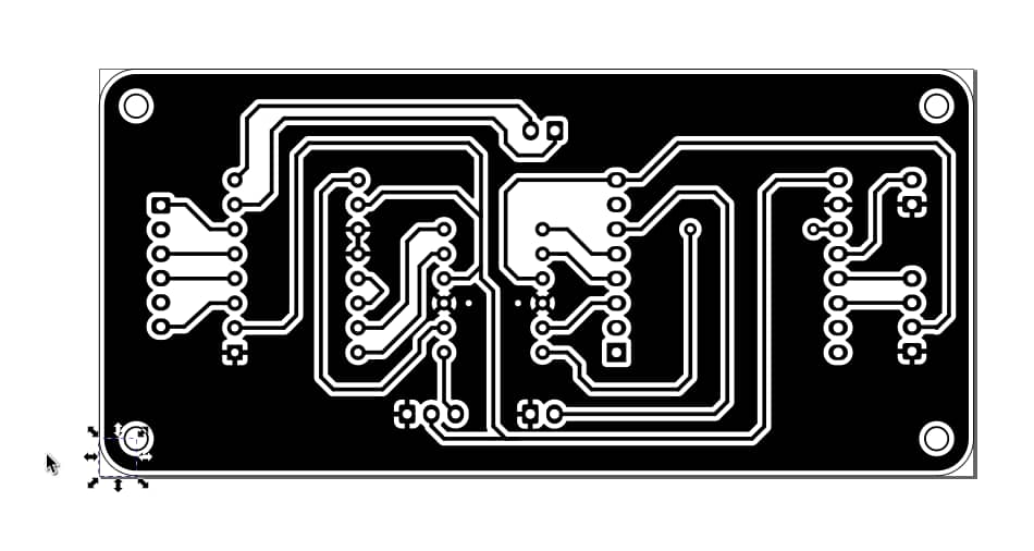
After fixing, the resulting copper traces were exported…
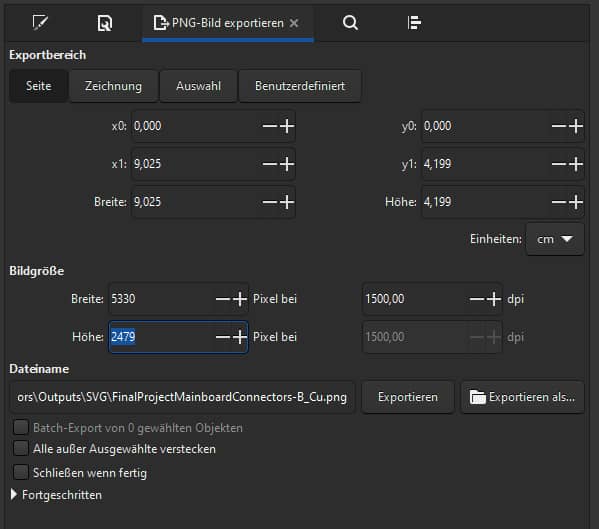
… as a 1500 dpi png:
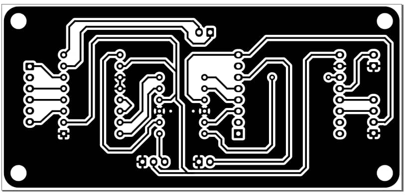
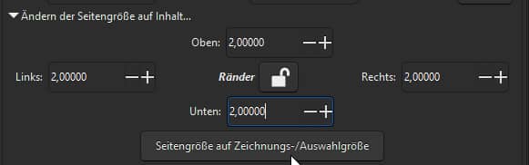
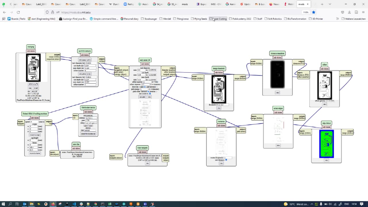
What followed was a number of things going wrong in Mods, mainly caused by me not setting a white background color in the SVG file (which totally throws off Mods when Inverting the image). The lack of a rim was also problematic, so I added a small white rim to the image on all sides:
I also had problems with the different files (copper traces, holes, edge cuts) not matching up sizewise, so I decided to redo everything in one single vector file:
I manually approximated the edge cut using a rectangle with radius corners instead of manually fixing the edge cuts path:
I then stenciled out the mounting holes from the rectangle…
… leaving me with the proper edge cut shape:
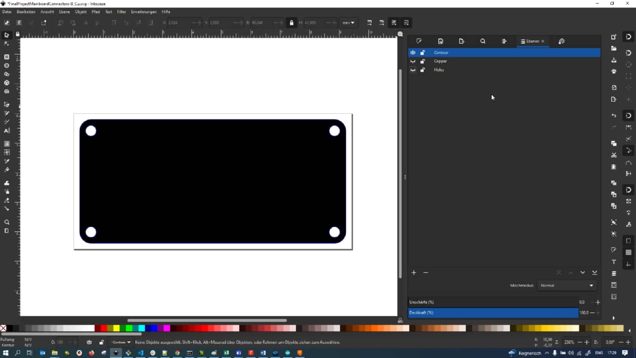
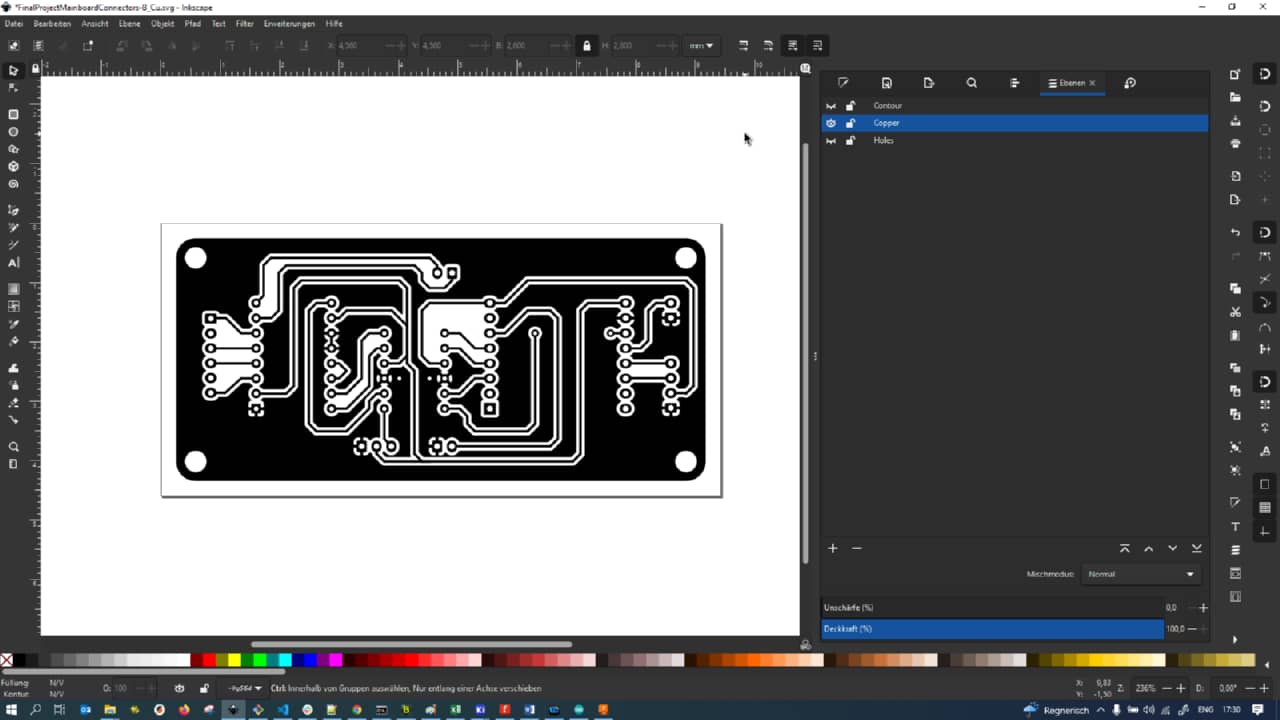
The copper design was in the same file (see the layers tab on the right, all layers are aligned in one vector file):
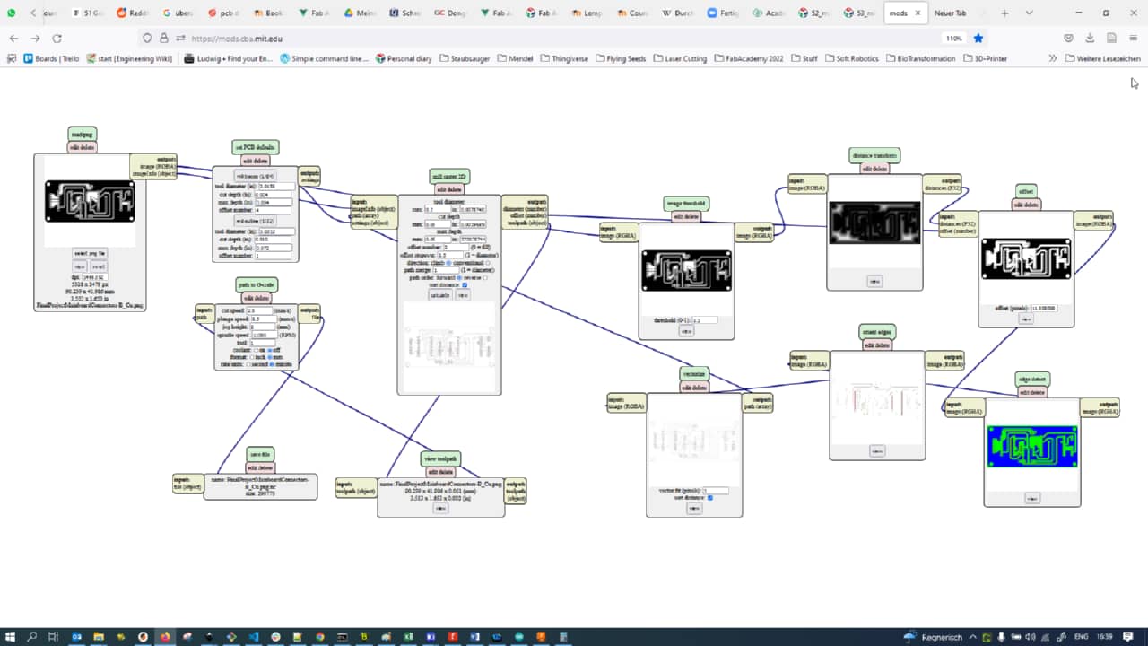
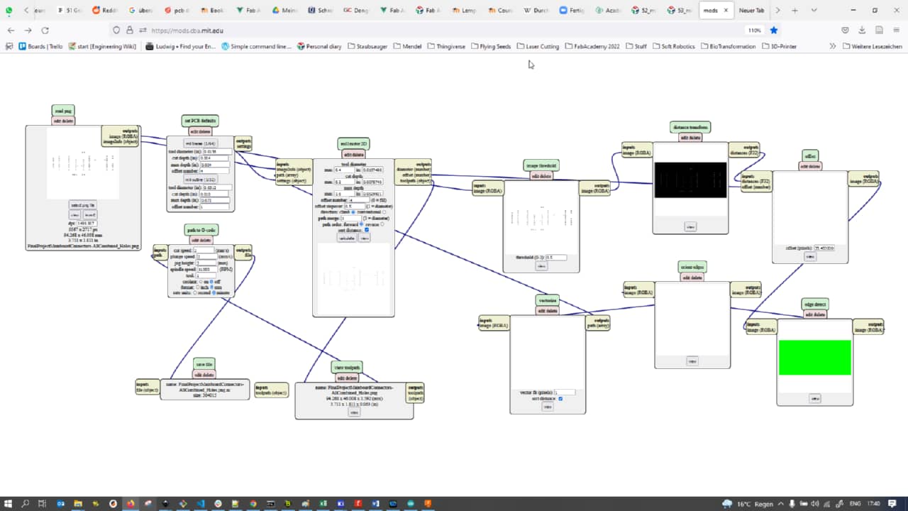
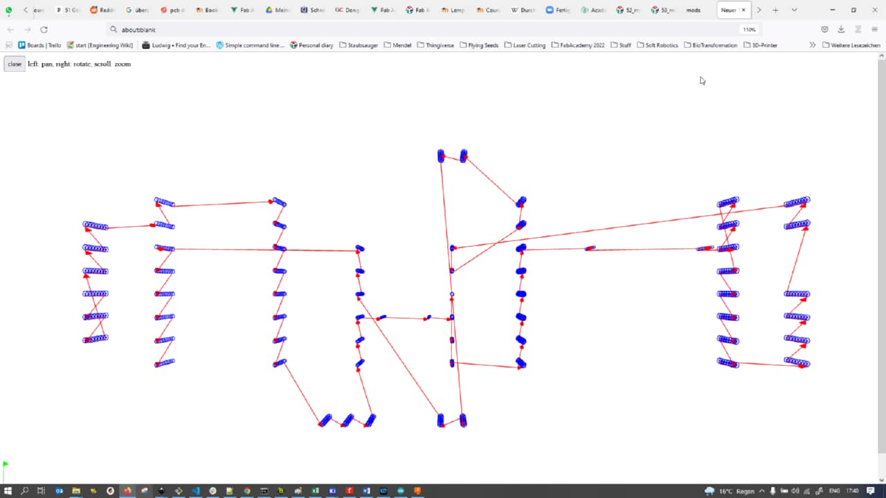
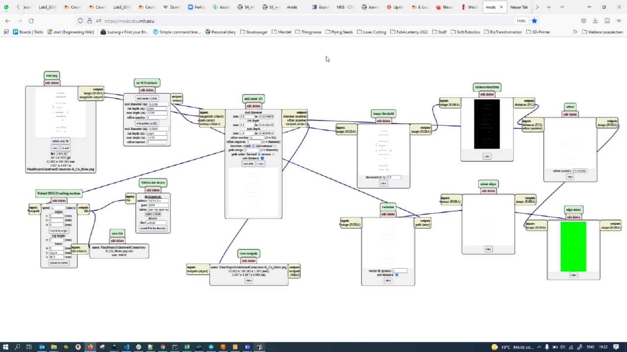
After eporting the pngs and loading them into mods, here is the setup…
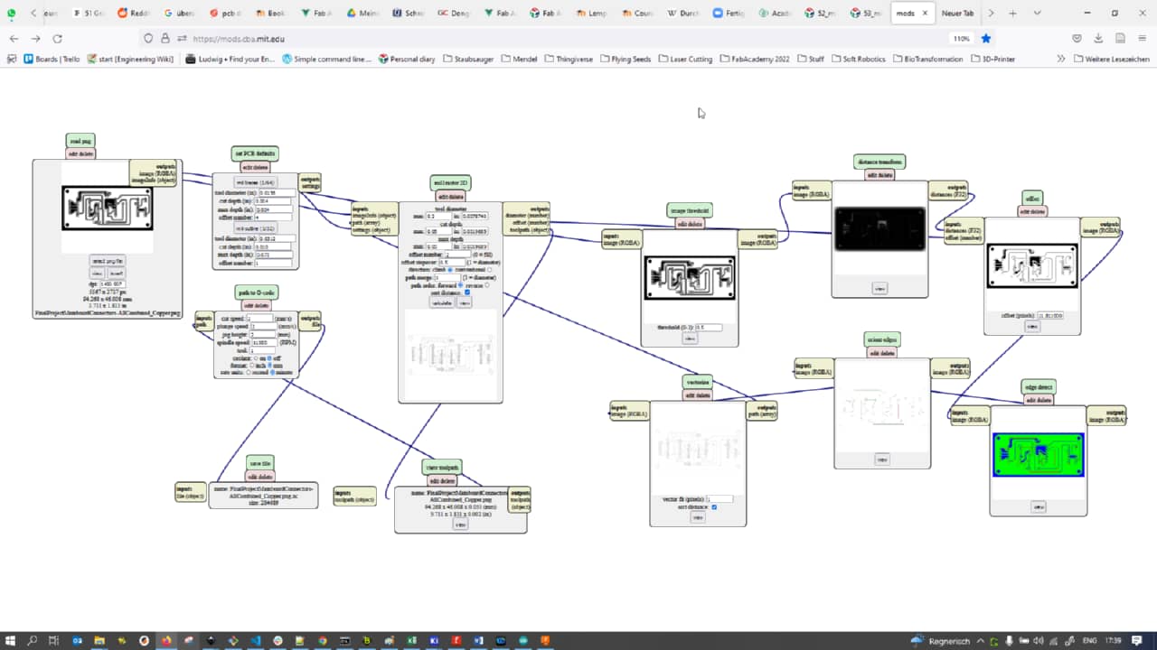
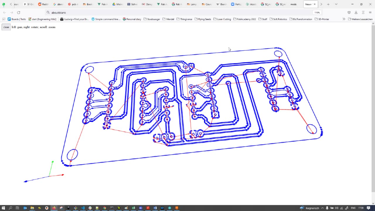
… and the preview for the copper traces.
Here the setup…
and the preview for the holes:
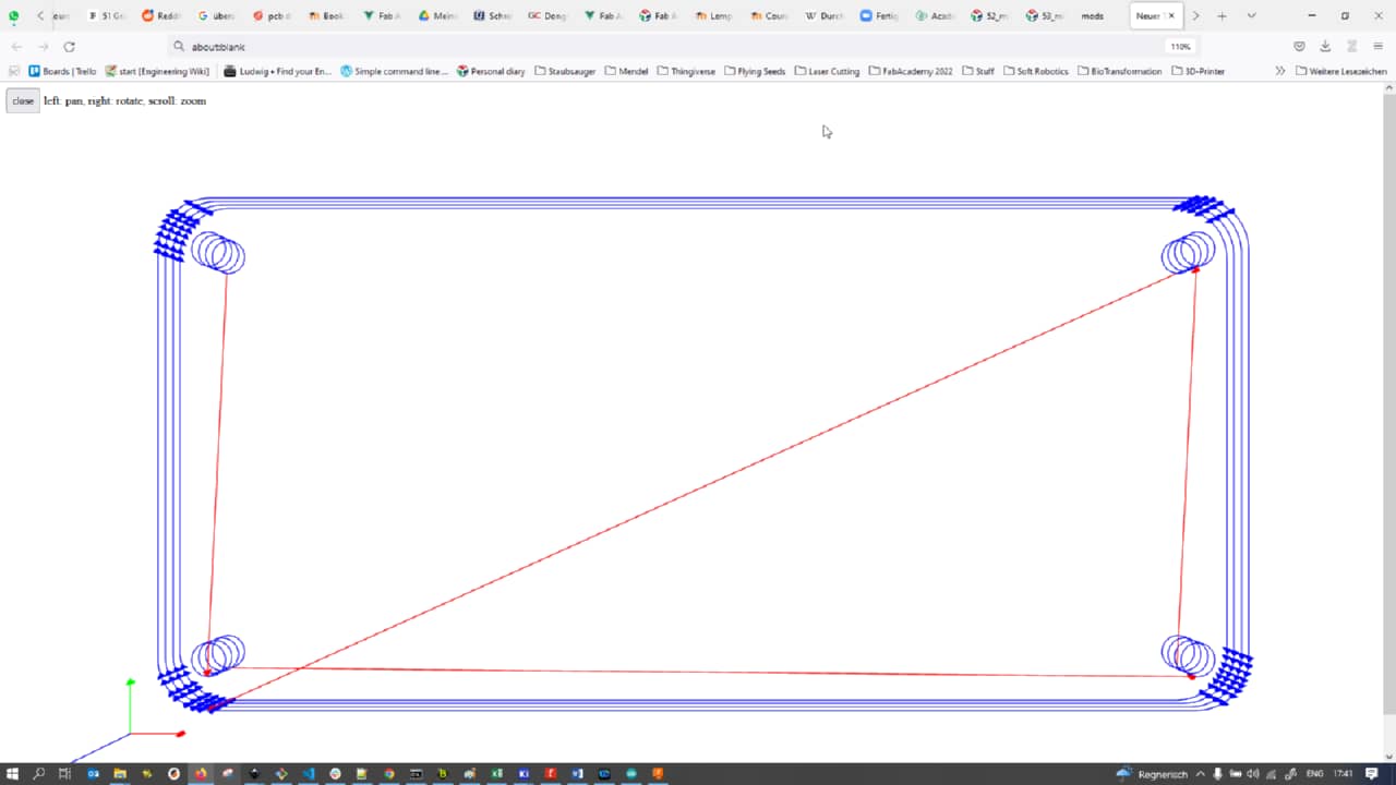
And here the setup…
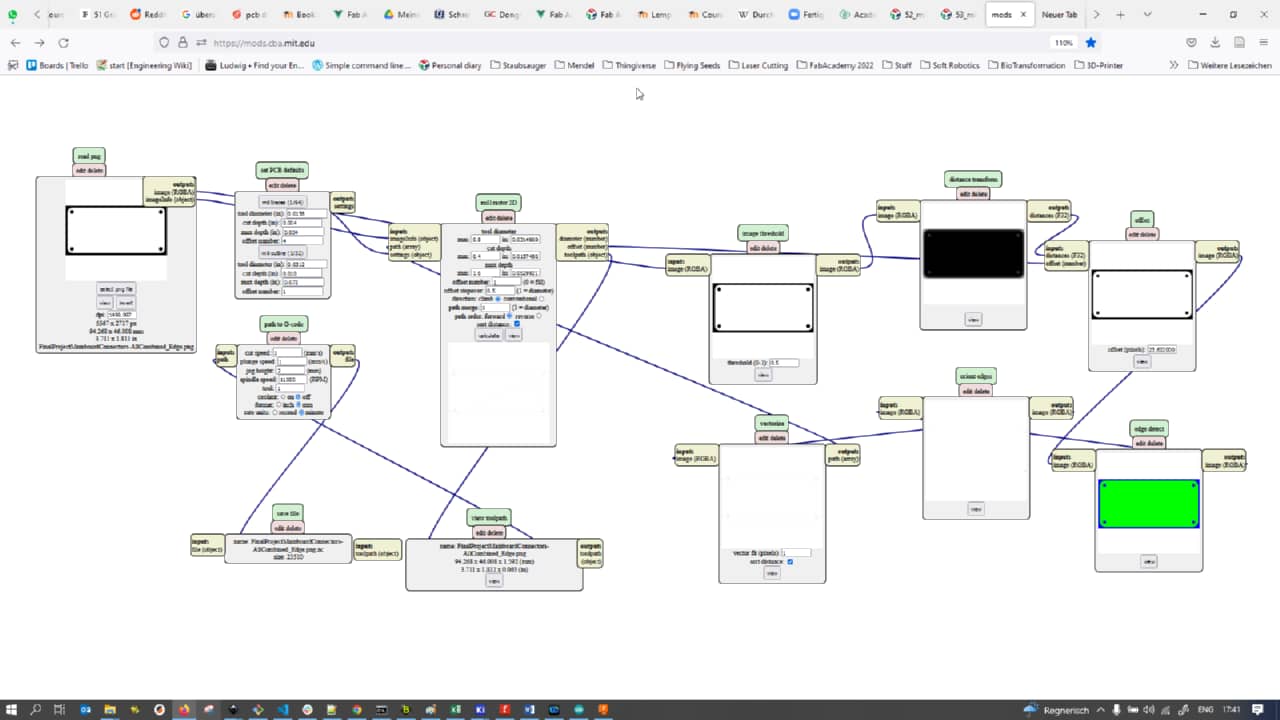
… and the preview for the edge cuts:
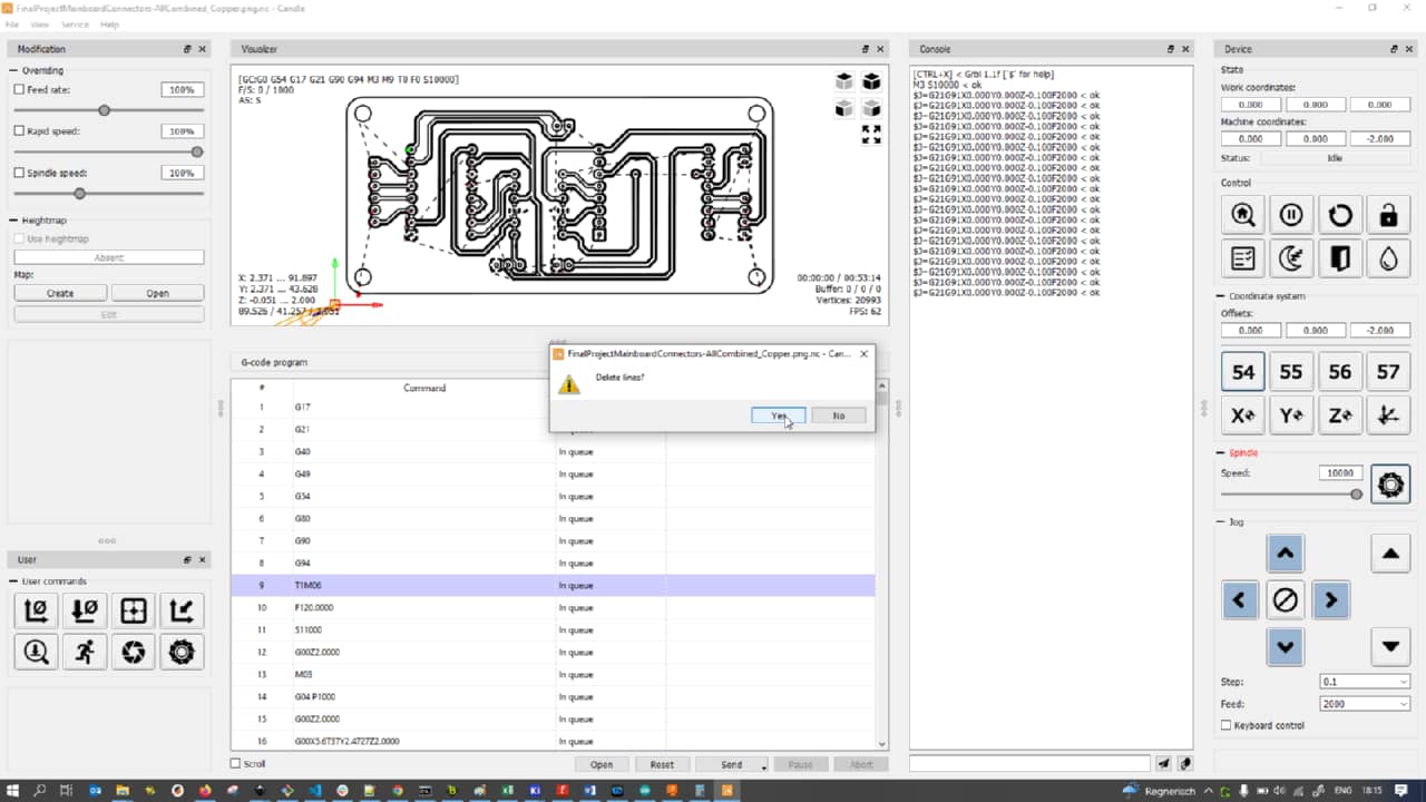
With a PCB on the Genmitsu PCB mill and the copper traces Gcode loaded into Candle, I deleted the offending T1M06 Gcode that always makes the mill stop and started milling. Unfortunately, the board did not come out well, as the underlay seemed to not be flat enough. I decided to actually try with the Roland SRM20 again instead of using the Genmitsu:
Since I was not really limited by space, I decided to make the traces in KiCad even fatter to avoid potential damage to the traces when a mill bit went too deep (using V-tipped mill bits, so cut width is a function of cut depth):
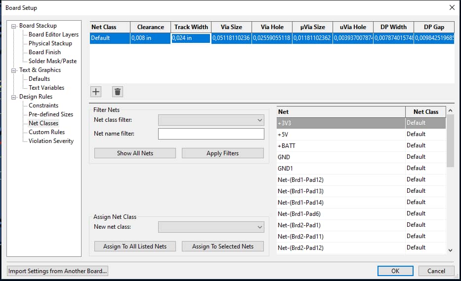
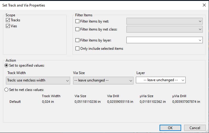
After making changes to the NatClass values, all traces can be updated simultaneously using the Set Track and Via Properties tool:
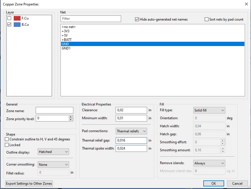
I also changed the ground pour plane’s values for thermal relief gap and spoke width accordingly:
I then used Clickmill for the Roland SRM20 to level the MDF underlay on the SRM20:
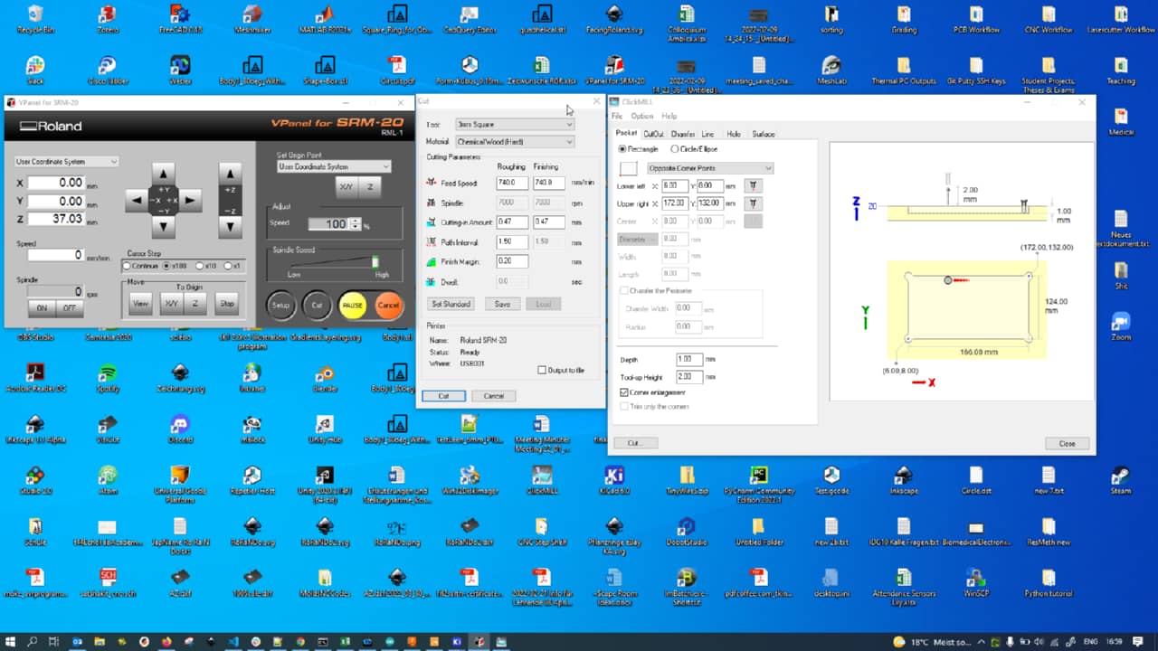
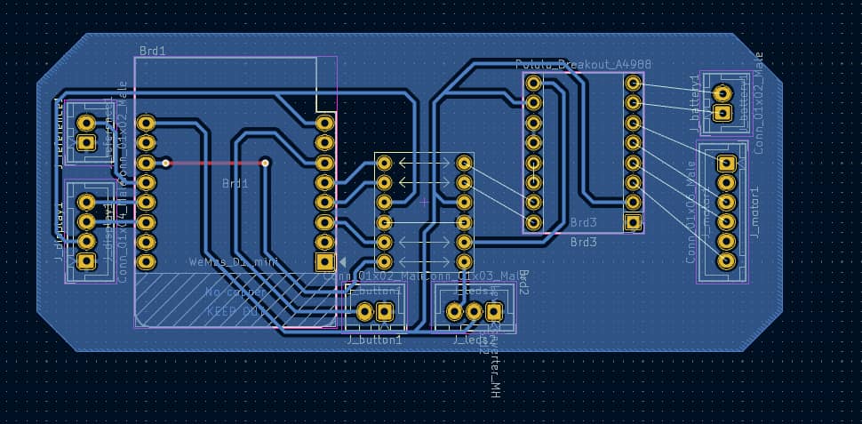
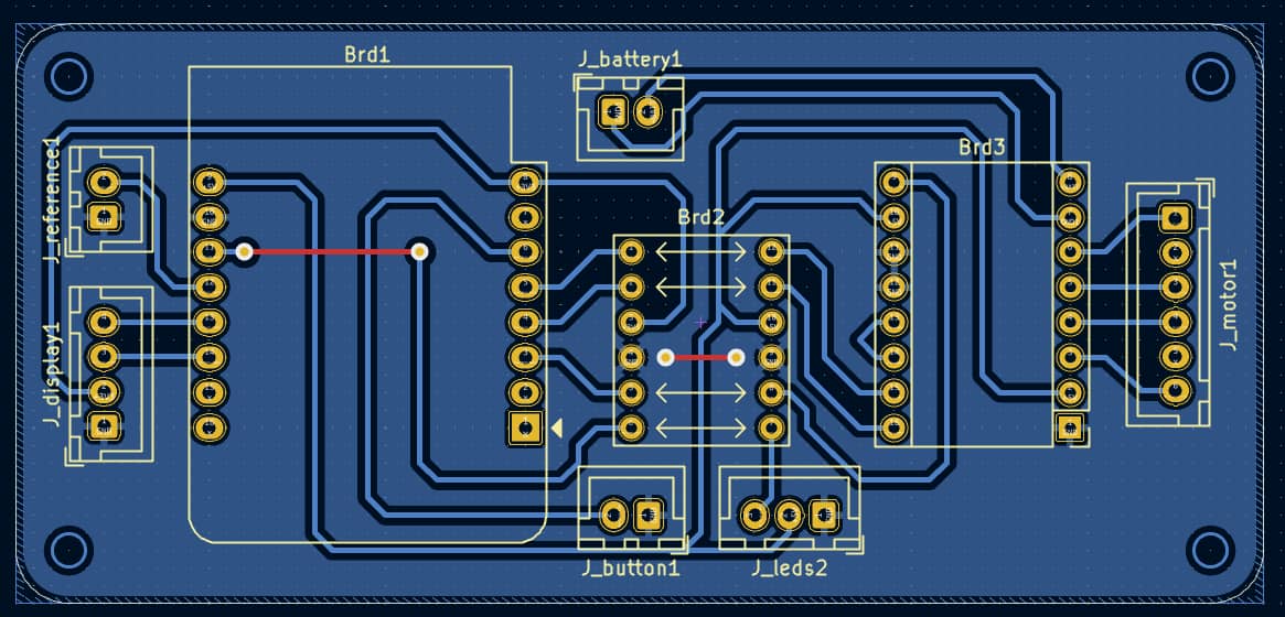
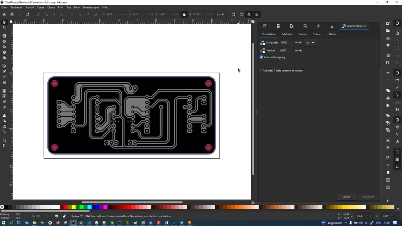
Here is the final board after fattening up all traces and also making sure all vias and pads were of the larger kind:
I then stacked the design in a single Inkscape vector file again, with a 5 mm rim, white opaque background and the edge cuts manually cleaned up:
After exporting to 1500 dpi jpgs and rotating them (as my board did only have the space vertically), I ran through Mods again for creating the Roland machine code. Here is the setup for the traces…
… and the one for the holes. The edge cuts were performed using the same mill and parameters as the holes:
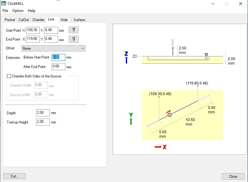
In the end, I had messed up and accidentally moved the edge of the board in PCB deign step beyond the USB connector, making it impossible for me to connect the USB conenctor. I taped down a piece of POM onto the PCB stock still in the machine and used clickmill to drill holes accorsing to the mounting holes of my board. I then was able to mount the fully stuffed and soldered board onto the POM block using screws…
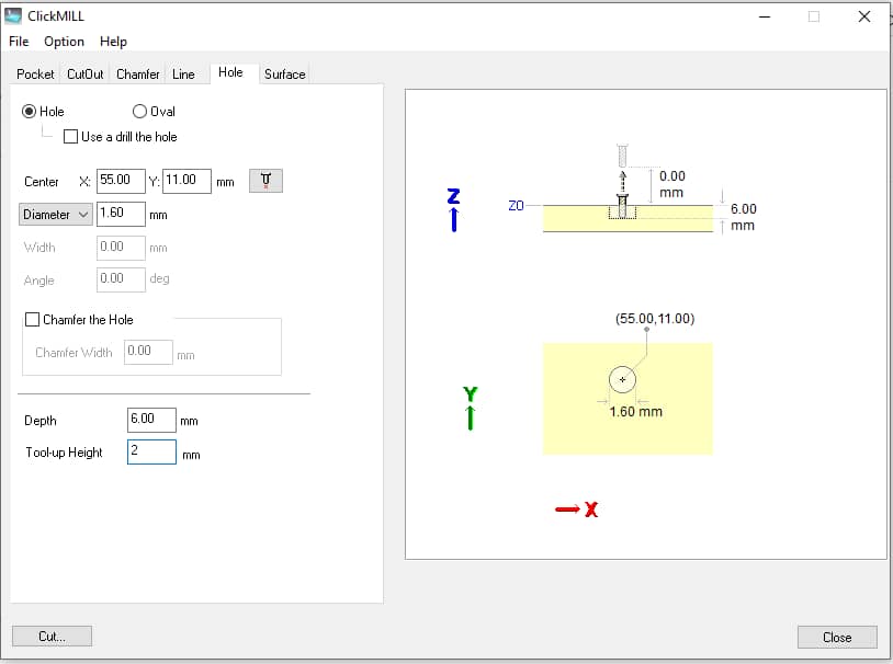
… and mill the USB port free again using a long, 1.5 mm diameter mill bit. Clickmill was also used to manually mill some lines to free the connector up again:
Making Everything Fit Together - System Integration
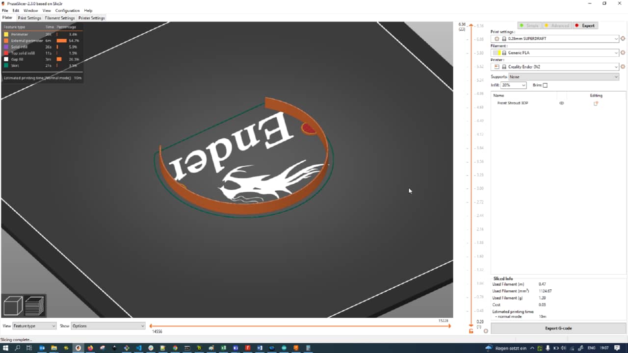
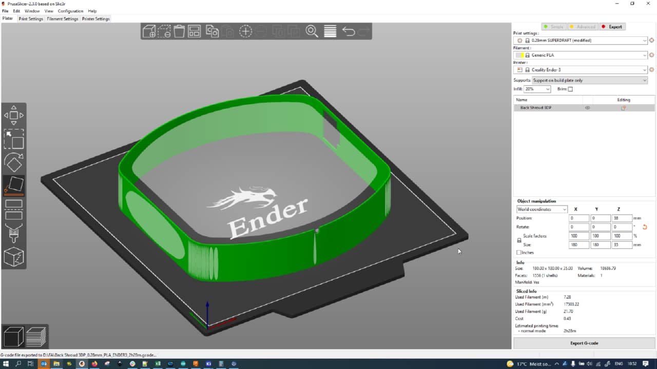
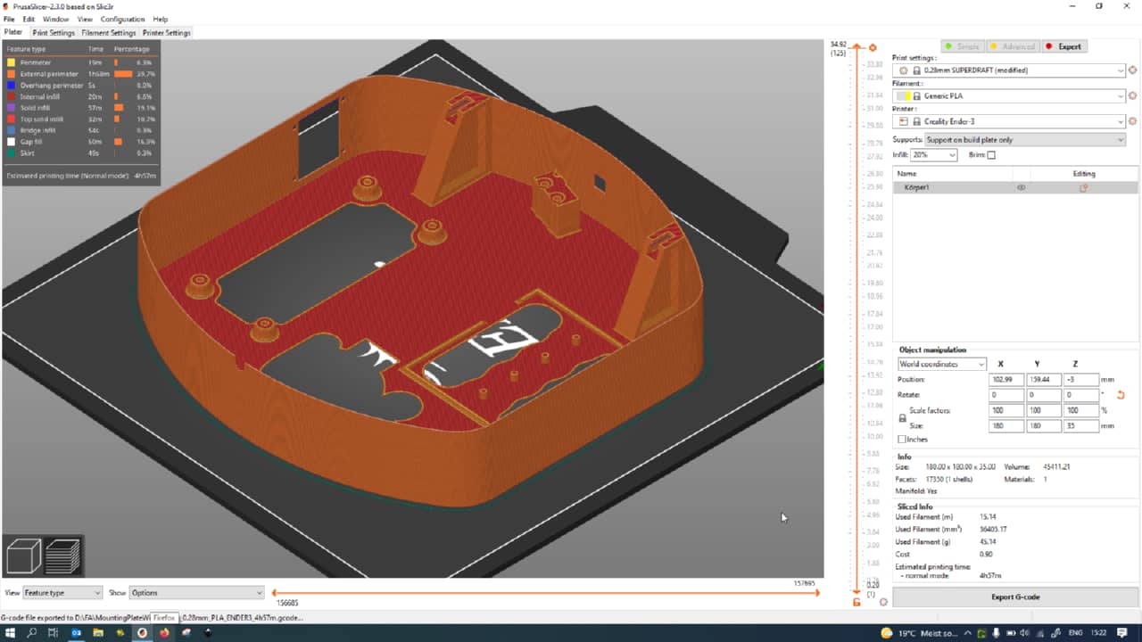
For hiding all the crimes on the back of the main plate, I had early on already desinges and printed (seen here in PrusaSlicer for slicing) a shroud with a cutout for the LED. It was very wobbly though and would have been hard to mount to the base plate, too:
When integrating all parts into one, I noticed that the indicator arm sometimes got stuck on the reference switch. I made the base of the indcator more massive to prevent that from happening:
Here we can see the old version with the little ledge prone to getting stuck at the microwitch’s wheel:

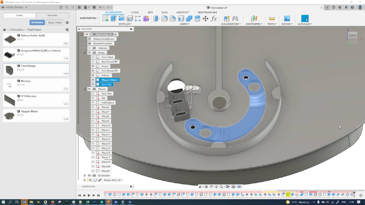
I also designed an alignment tool for adding magnets to the baseplate, concentric with the motor and mounted using the motor’s screws:
After finishing up, the part lokked like that, with holes for the motor mounting screws to pass through and for the magnets to be glued into:
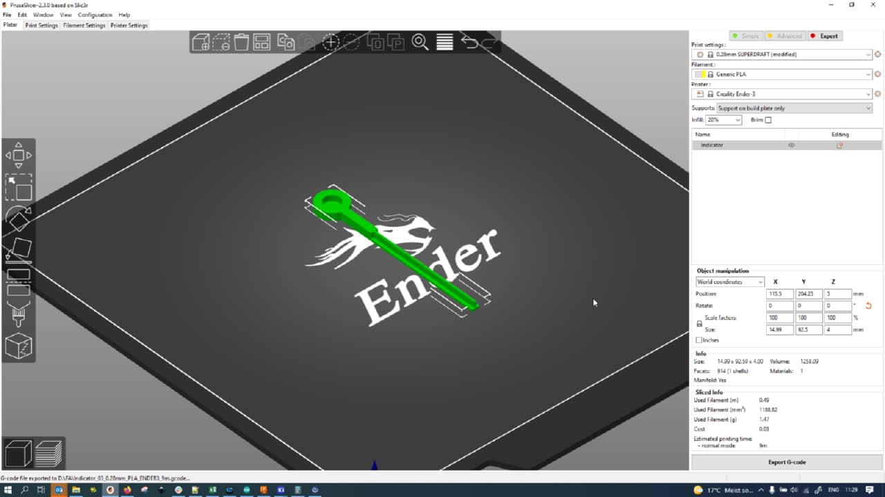
Here are the print parameters for the indicator arm in PrusaSlicer:
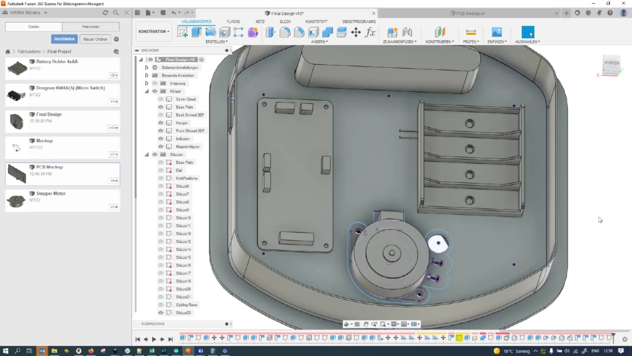
I also tried fleshing out the PCB mockup a bit more, but although KiCad has a module for doing 3D renderings…
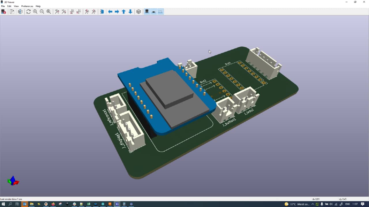
… there is no way to actually export them, so I roughly added some more mockup details (shape, mounting holes, connector locations) to the PCB mockup component:
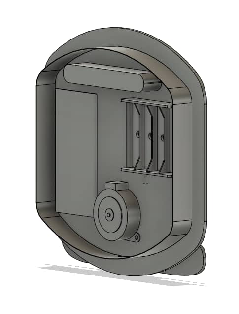
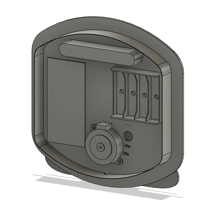
Finally, here is a view of the final back plate integration unit, which provides screwposts for both PCB and a top microswitch to toglle the machine. It also provides posts to be melted with soldering iron for mounting the battery holder and a cutout for the OLED screen (with screw mounting holes). Hangers for nails or screw were also integrated into the piece, as well as the complete shroud surrounding and hiding the electonics:
Final Bill of Materials
After week 18 where the bill of materials was first estimated, I changed amounts as tracked roughly and added some more things to it during development:
| Material/Component | Quantity | Unit price | Total Price |
|---|---|---|---|
| Plywood | 0.04 m² | 46.04 €/m² | 1.84 € |
| PLA | 51 g | 15 €/kg | 0.77 € |
| D1 Mini NodeMcu with ESP8266 | 1 | 11.99 €/3 pcs. | ~ 4.00 € |
| A4988 Stepper Motor Driver | 1 | 9.99 €/5 pcs. | ~ 2.00 € |
| NEMA 17 Stepper Motor | 1 | 10.69 €/pc. | 10.69 € |
| OLED Screen | 1 | 19.99 € /5 pcs. | ~ 4.00 € |
| Micro Switches | 2 | 6.79 €/20 pcs. | ~ 0.68 € |
| FR1 PCB Stock | 1 (~ 7 x 10 cm) | 11.99 €/15 pcs. | ~ 0.80 € |
| 4x AA Battery Holder | 1 | ~ 0.67 €/pc | ~ 0.67 € |
| AA Battery | 4 | ~1.29 €/4 pcs. | ~ 1.29 € |
| Cables, Crimps, Hardware etc. | 1 | ~ 2.00 € | ~ 2.00 € |
| µUSB Charger | 1 | ~ 5.00 €/pc | ~ 5.00 € |
| Total | 33.74 € |
Global Review Changes
During global review, I added another daughter board to the final project device which externalizes a button using I2C communication. Since this also tied into some rework to be done in Networking week, I added it as an Addendum in there. The updated firmware files are also found in the week 15 design files Here is a video of the added feature tied into the final project device:
Design Files
-
Gantt Chart (XLSX, Microsoft Excel)
-
2D Symbol Design Files (SVG, Inkscape):
-
eCAD Design Files (ZIP, Kicad 6.0 Archive):
-
3D CAD Design Files (F3Z, Fusion 360):
-
3D Print files (3MF, Prusa Slicer):
-
Wemos D1 Mini Firmware (INO, Arduino IDE):