Mechanical Design and Machine Design
"A Thing That Does A Thing"
Description
The Fartigator 3000 is a janky little non-machine that closes and opens its mouth when triggered by a person and farts bubbles out its back when not doing so. The machine is controlled by an Arduino Uno that interfaces a number of sensors and actors to make this happen.
In the back of the machine, there is an HC-SR04 ultrasonic range sensor. When an object comes within 30 cm of the sensor, it triggers and sends a signal back to the Arduino. Upon triggering, the Arduino starts closing the jaw by extending a linear actuator's (12V, 1500N, 50 mm stroke length) piston. As the microcontroller cannot directly supply the current needed for a beefy motor as this, it controls the motor via an L298N Dual H-Bridge motor control module.
Since the motors are running at 12V, the motor controller is supplied with 12V from a plug-in power suopply. Conveniently, the motor controller also carries a 5V voltage regulator on board, which powers the whole logic circuit (Arduino and friends), eliminating the need for a separate power supply.
The Arduino controls the motor such that it extends the piston slightly and then retracts it again, simply by running the motor for given amounts of time. There is no sensory feedback from the motors, though the linear actuator does have limit switches on both ends, which are used for an initial homing sequence when powering up the machine, where the motor just retracts long enough to safely run into one limit switch and thus establish a home position.
For emergencies, a microswitch is installed in the back of the machine. When triggered manually, it initiates the power up homing procedure, making the jaw open as wide as possible and driving the motor back to its home position.
When the motor switches off after closing and opening the mouth, a signal is sent to a children toy bubble machine that is also situated in the back of the machine, which then starts making bubbles until the jaw is triggered again. The bubble machine, though installed in the back of the Fartigator 3000 by default, can also be freely placed in the room. It runs on its own power supply and uses an Arduino Nano to switch on the bubble making motor using a mosfet. The start and stop signals from the main Arduino are transmitted by an nRF24 2.4Ghz radio module.
Part 1 (Aaron's Part)
Hero Shot
Final Assembly
File Downloads From This Week
- ZIP file with all CAD parts and assembly
- Click Here for Leen's Contribution
- Click Here for Roland's Contribution
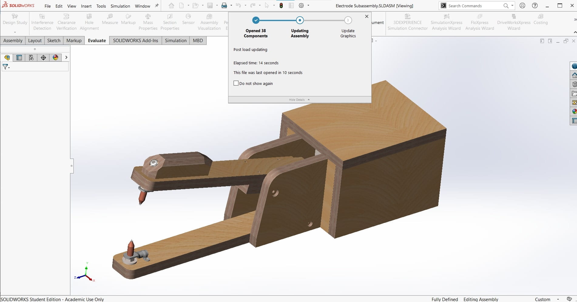
CAD Assembly
Initial Reaction
I am really excited for this one! Machine design is my passion and it's quite literally why I am taking this course. As usual, Neil gave us a brief introduction to the possibilities as well as some great examples of past submissions. There are so many badasses that are alumni of FabAcademy! It's very inspirational. For this assignment, we only have a group project; we are to design and build a machine that is functional, actuated, automated and applicable. Roland is still recovering from Covid19, so I guess Leen and I will be getting started tomorrow, and he can help once he is feeling better. I can't wait! I want to start designing right away.
After Local Workshop
The local workshop was very short this week. We met for about a half hour to discuss our ideas for the machine we want to design and build. The Kleve team is going to build a spot welder for our lab. We still need to work out the details of meeting the requirements of the assignment, but the machine will be a nice addition to the lab if we are successful.
Detailed CAD Design
The Plan
A few weeks ago, my dad sent me a video of a DIY spot welder made from an old microwave transformer. I thought it was a cool idea and we could use one for the lab, so I sent it to Leen and Roland since we were on the market for a machine to build this week. They liked it too so we agreed to make it. We had to make a few adjustments to make it more suitable for our purposes and to fulfill the requirements of the assignment. Actuation lends itself easily to this machine since we wanted to add a foot pedal to the original design anyway, but We had difficulty coming up with a way to automate it without making it exponentially more complicated or reducing its overall functionality. In the end we decided to add a wireless bubble machine to it. This will serve as a warning sign that the welder is in use as well as a distraction to look at instead of the arc (spot welders don't make arcs that are actually dangerous, so this is more about functionality). And of course, the intensity and duration of the bubbles can be programmed and performed automatically.
This Document
Since corona is disrupting the normal flow of our group right now, we decided to divide our efforts for the design stages. I will handle the mechanical design, Leen will take care of the electronics, and Roland will do the programming. Since they need the mechanical design to be largely done in order to get started, I decided to get busy right away.
There are over 20 parts to this machine so I have chosen not to document every step of the CAD design of every part. I think that would just be tedious for us both. So, for the purposes of this process documentation, I decided to only write about the design decisions and the overall process of designing as well as the finished detailed CAD design. For the sake of brevity, I will only include the highlights of the CAD work here. More images and information are available upon request if the reviewers feel that what I have included is insufficient.
Info from Screenshots
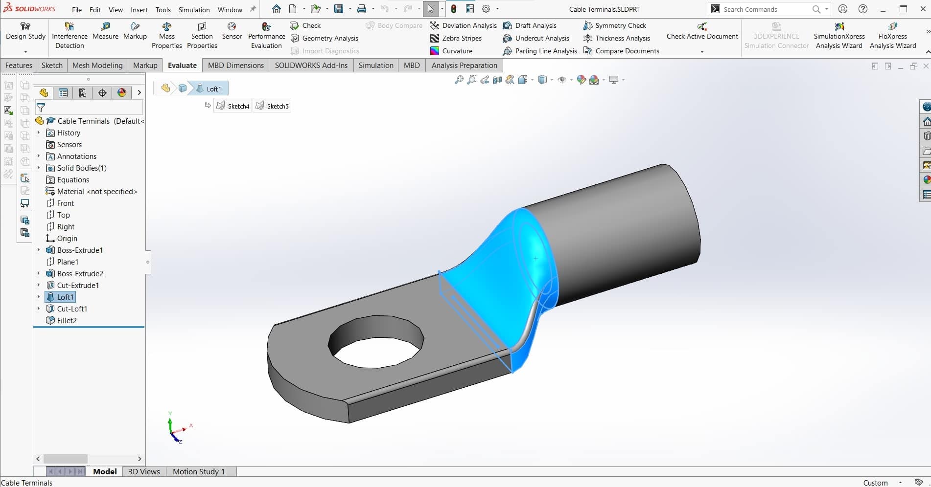
I began by re-watching the video. There were a couple useful screen-grabs that allowed me to figure out what hardware the maker was using, and from there, I was able to speculate about the overall dimensions of the machine and the components that were being used. My first CAD part was the cable terminal and everything else was built based off of that.
Copper Electrodes
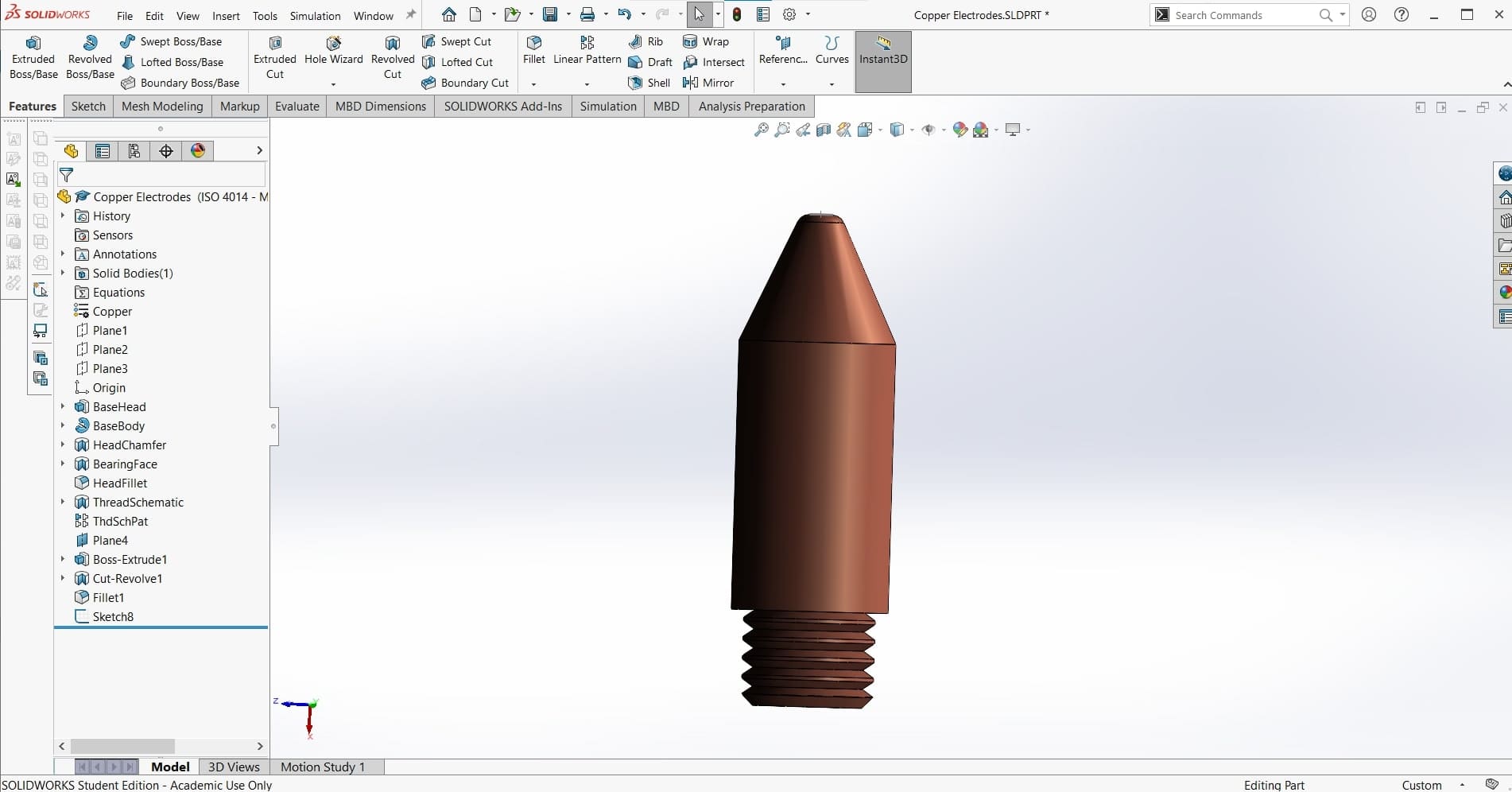
Next I made the copper electrodes that would be the welding tips...
Cable Clamps
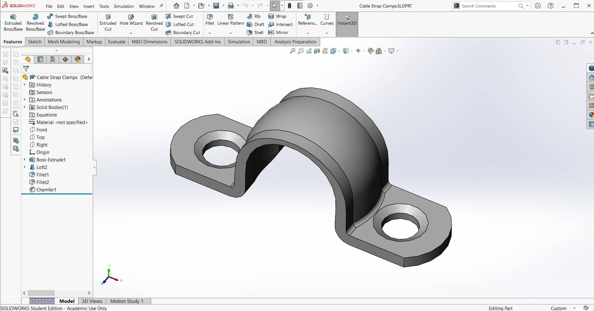
...and the cable clamps. These are are simple parts so there is no deed for too much extra detail.
Bottom Jaw
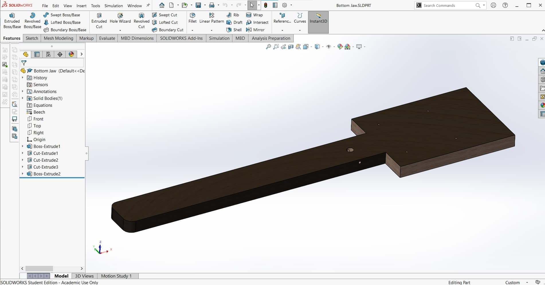
Once I had the welding ends of the machine assembled with the necessary hardware and mated to allow the desired degree of freedom, then I was able to make the lower jaw part that would serve as the base of the machine onto which everything else would be positioned.
Tension Spring
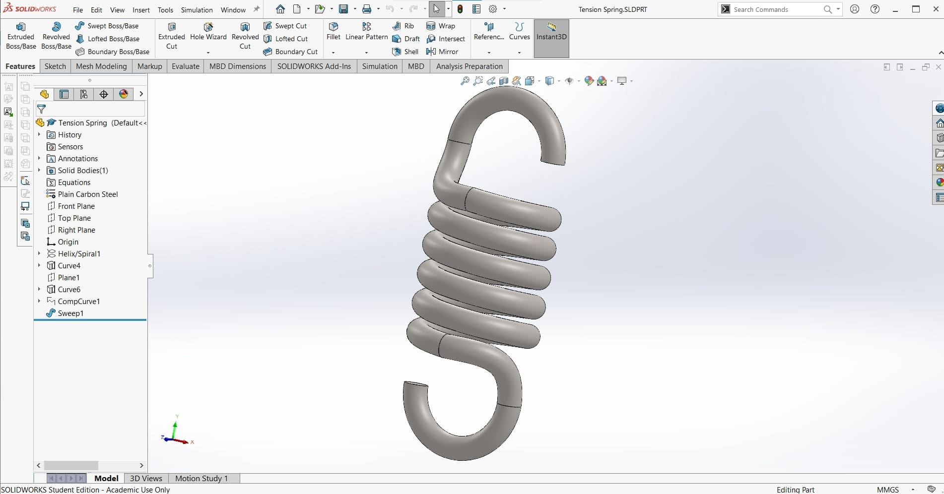
Next, it was time to select the tension spring. Using the size and force parameters I had already worked out, I used this spring calculator to determine the dimensions of the spring we would need. Then I stole a model from GrabCAD and adjusted it to fit the dimensions of our spring.
Eyebolts
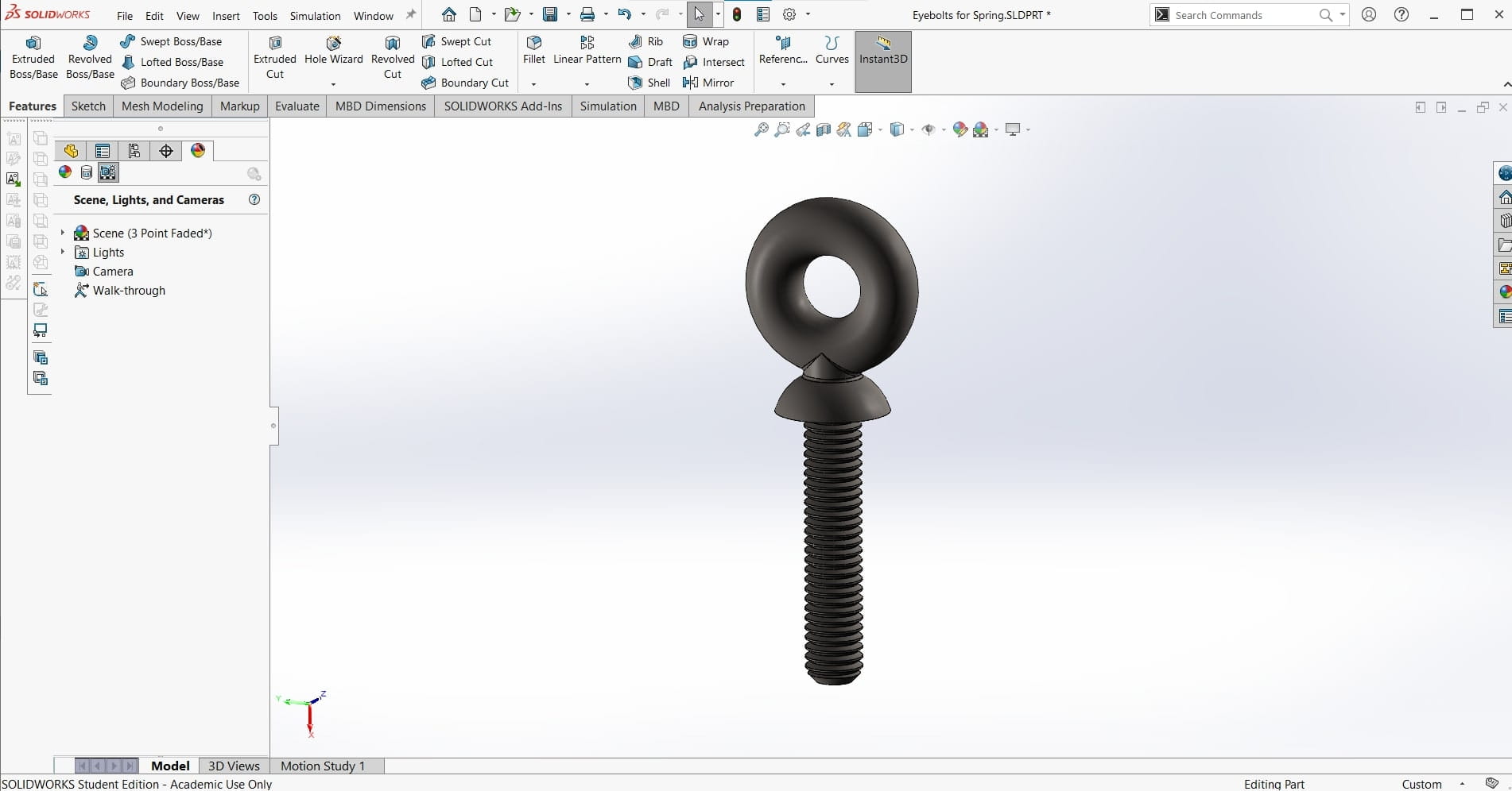
For the eyehole bolts, I couldn't find any models for smaller configurations, so I just decided to make this part myself as well. I started with an M5 bolt, and then extruded the shoulder and eyehole using the Revolve Extrude feature.
Top Jaw
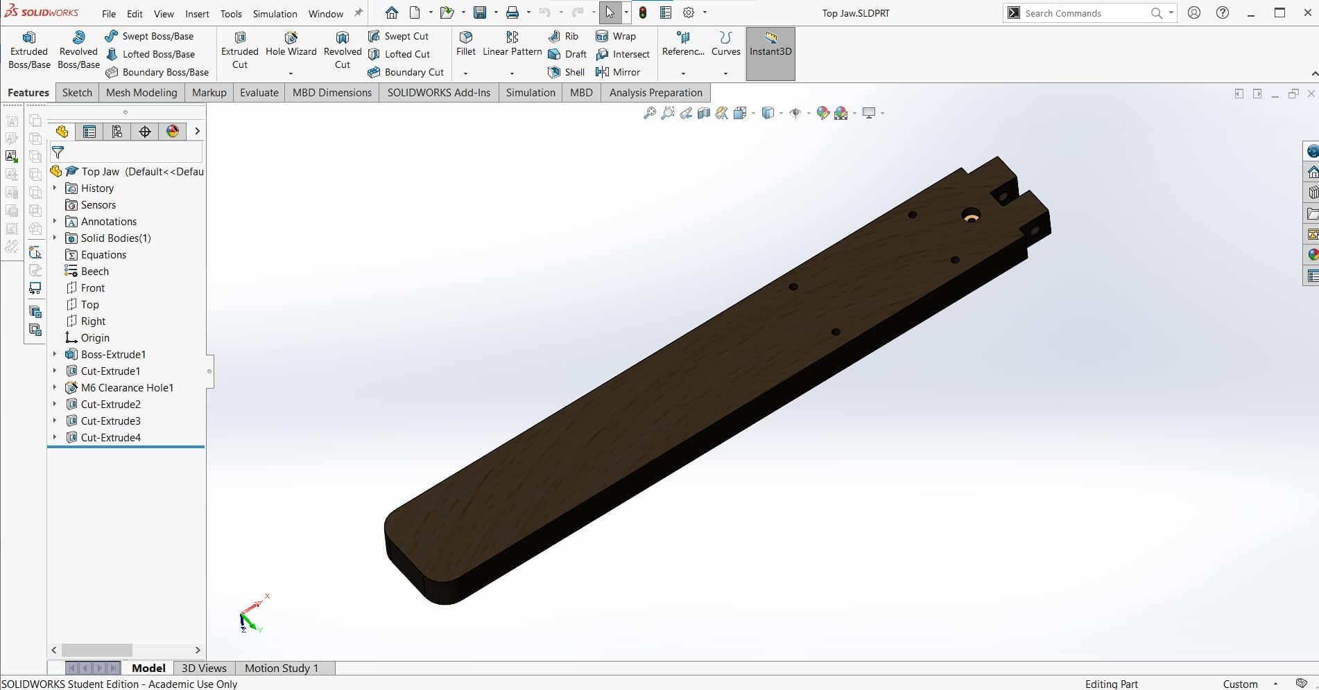
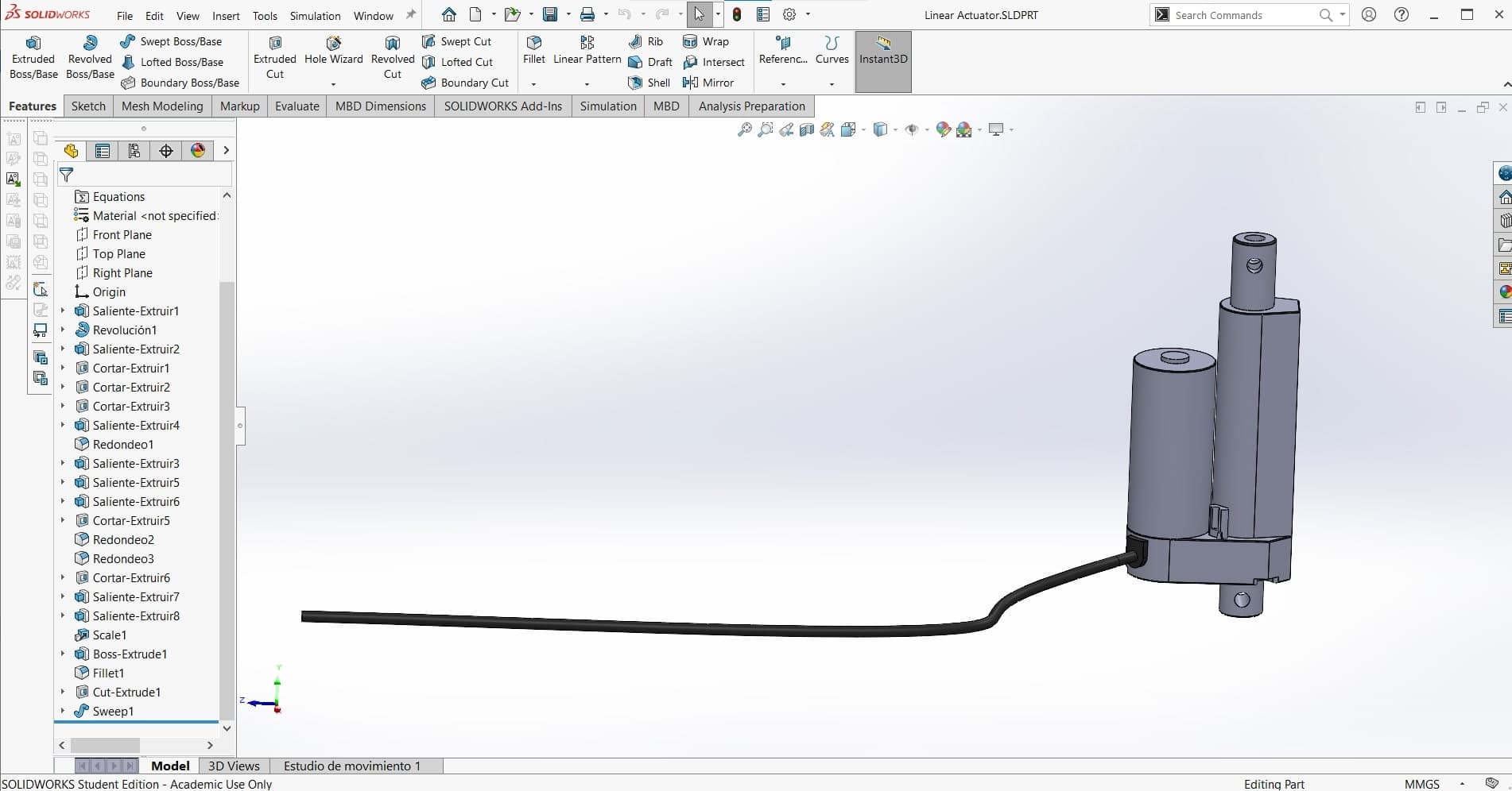
Next I added the linear actuator. Once again, I looked at my force loads and the available space to select the necessary servo. I found a model for one of the configurations in the series that I wanted, and then scaled it to the correct dimensions using the Scale tool.
Linear Actuator
Once I had all of the components for the welding arms attached to the bottom jaw, it was time to create the top jaw. Since everything was already properly lined up, this part was easy to make. I removed the notch from the back to fit the linear actuator.
Microwave Transformer
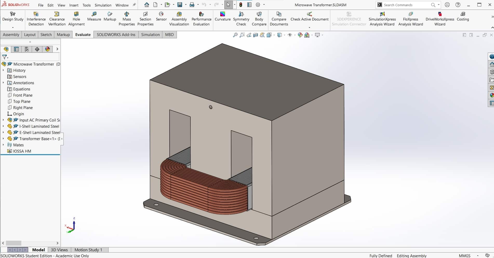 We took the transformer out of the old microwave and looked up the datasheet. Then I found a model once again to get me started. The transformer I downloaded was too detailed for my purposes so I replaced the 152 0.5mm layers of the steel core with solid parts. I also removed the top coil (the coil with the most windings), and then added the subassembly to the assembly.
Fan
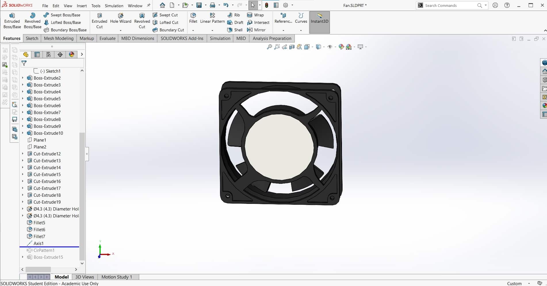
I followed a similar process for the cooling fan. I found a model for a computer box-fan that was the right size, but it was overly complex for my purposes so I removed some features to simplify it. Also strangely, the model was missing one of the five fan blades to I used a Circular Pattern to add it in.
Fulcrum Panels
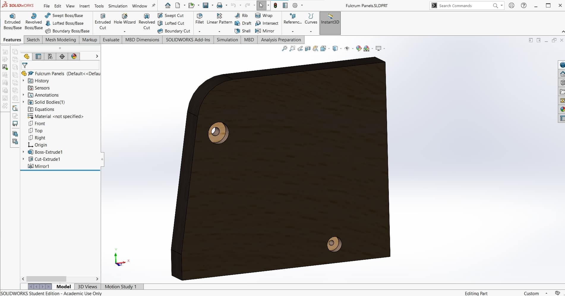
Once I had all the major components in the assembly, I could focus on the structure and housing that would hold it all together. I made the side pieces to hold the pin joint first. Adding the oblique side with the large filet will be more difficult to manufacture, but I am hoping it will be a good trade for a bit more working room between the welding arms.
Handle
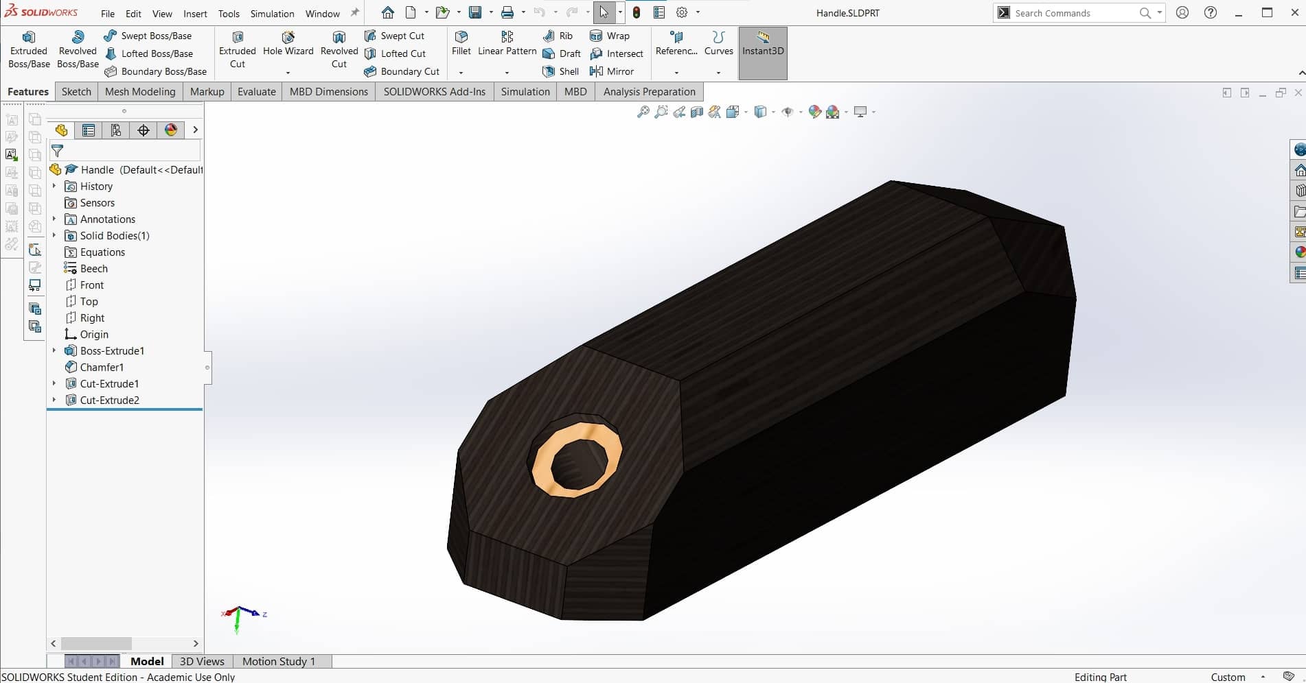
I didn't like the way the upper jaw was made in the video; it doesn't look very comfortable to use. So I decided to add a handle to the top of it that will also house the activation button.
Pushbutton
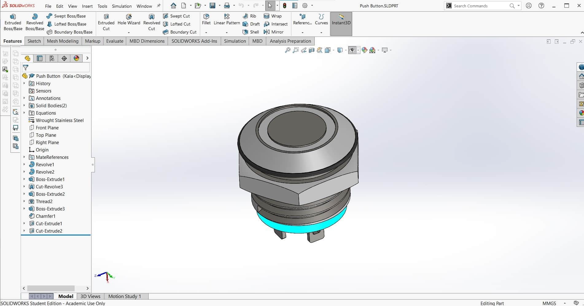
I also found a pushbutton on GrabCAD ton insert into the handle and activate the current.
Ugly Wooden Housing
Finally the function of the machine was complete, so it was time to create the housing. I was initially thinking about a plywood housing made from the same material as the welding arms, but it make the machine look clunky and unappealing to me.
Sheet Metal Housing
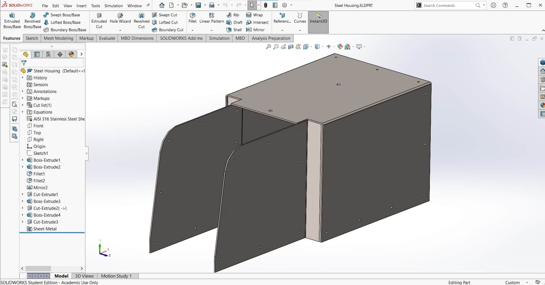
Leen suggested using sheet metal for the housing instead of wood. I don't have much experience bending metal and we don't have any special equipment for it in the lab, but it's a fairly simple part in terms of geometry, so I thought I would be able to figure it out using enough bar clamps lol. We had some 1 mm mild steel scrap in the lab that was perfect, so I designed the part with that in mind.
Cross Section
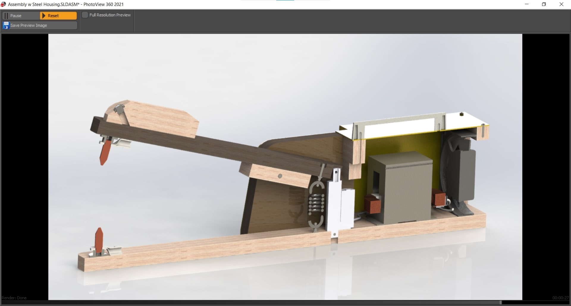
Finally, the assembly was complete. Here is a cross-section showing the inner workings of the welder as well as the relative arrangement of the components. In the end, I was really pleased with the results. The low profile steel housing was so much more aesthetically pleasing than the bulky plywood. Good suggestion Leen.
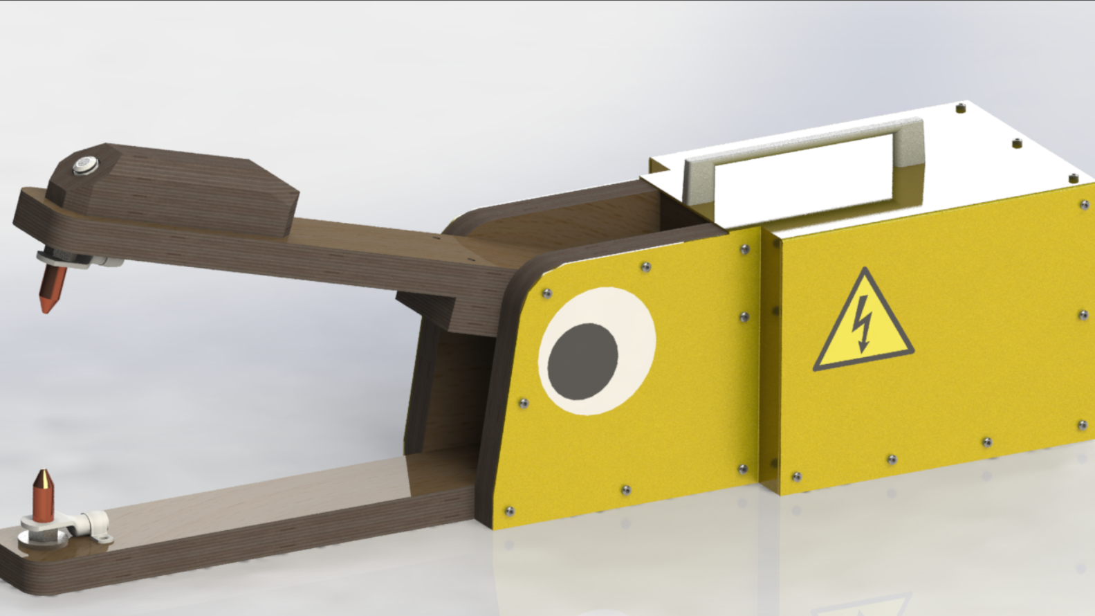
Googly Eye
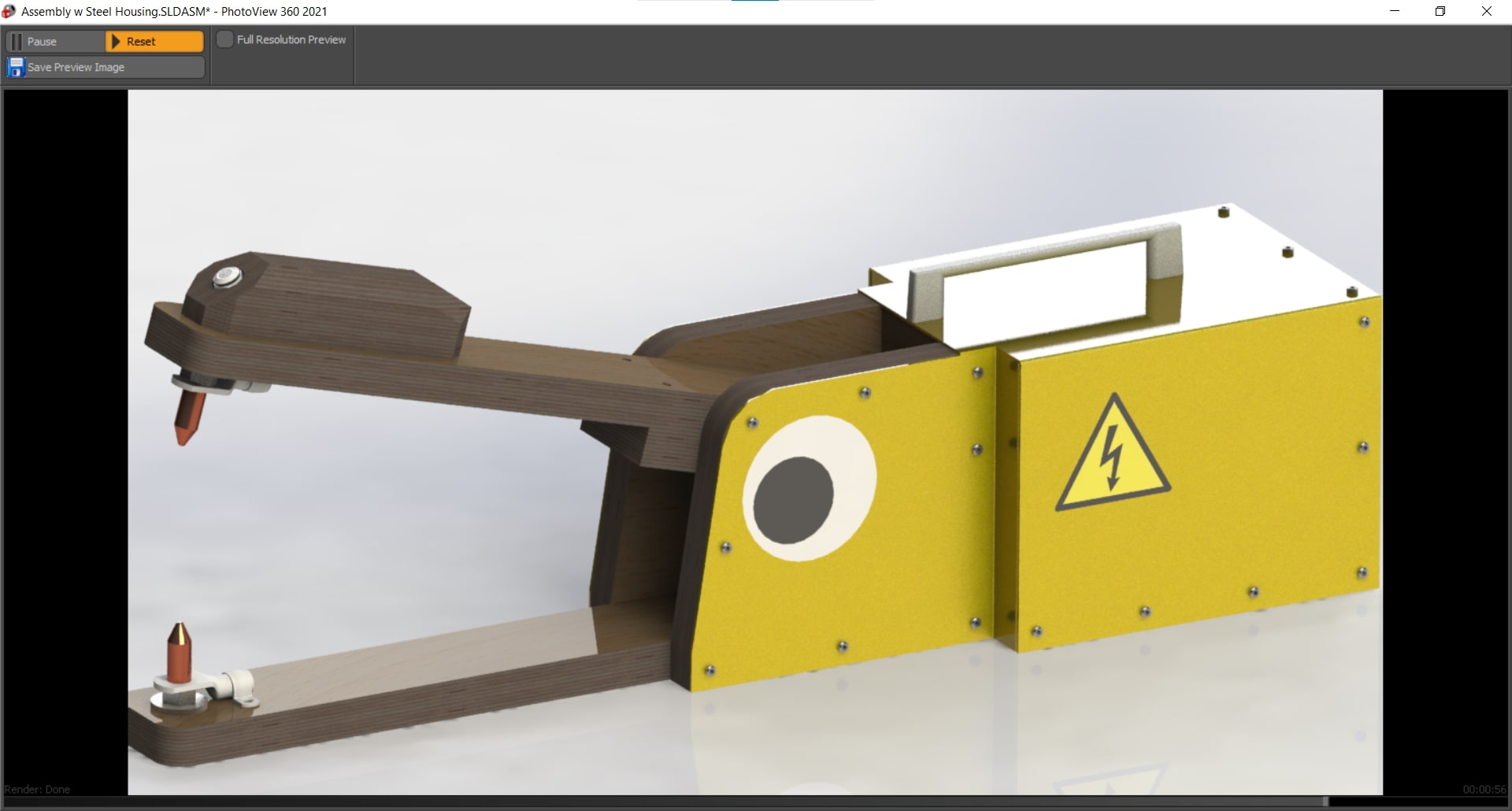
Here is the rendered assembly with all of the appearances. I also added a few stickers to give the device a bit more life. I can honestly say, this is the first time I have ever used CAD software to design a googly eye lol.
Description of the Design
Mechanism
The mechanical mechanism is fairly simple. It is essentially just two arms linked together with a pin joint allowing for a rotational degree of freedom. At the other end of the arms, sit the electrodes used for welding. There is a tension spring connecting the mobile arm to the base so the connection is always pulled apart unless the spring force is overcome.
Actuation
A linear actuator is positioned behind the spring. This will allow the foot pedal to be used to actuate the welding arms and to supply the energy during welding. When the foot pedal is half-pressed, the mobile arm rotates to make the connection between the electrodes; and when it's fully pressed, the current flows.
Automation
The bubble machine comes on automatically when welding as a warning sign to not look at the arc and as a distraction providing something else to look at. However, it can also be programmed to turn on and off on demand as well as to produce bubbles for a preset amount of time.
Functionality
Hopefully the function of the machine is obvious. We needed a spot welder, so we built a spot welder. Spot welders are exponentially more usable when they can be operated hands-free, so we added the foot pedal to improve the functionality of the device. Automated spot welders start at around 15k so we had no delusions about being able to achieve that level of quality in two weeks with essentially no budget, so we decided to go another direction for the automation side of the project and include a bit of whimsy that also serves a functional purpose.
Manufacture
Making Parts
Fabrication Plan
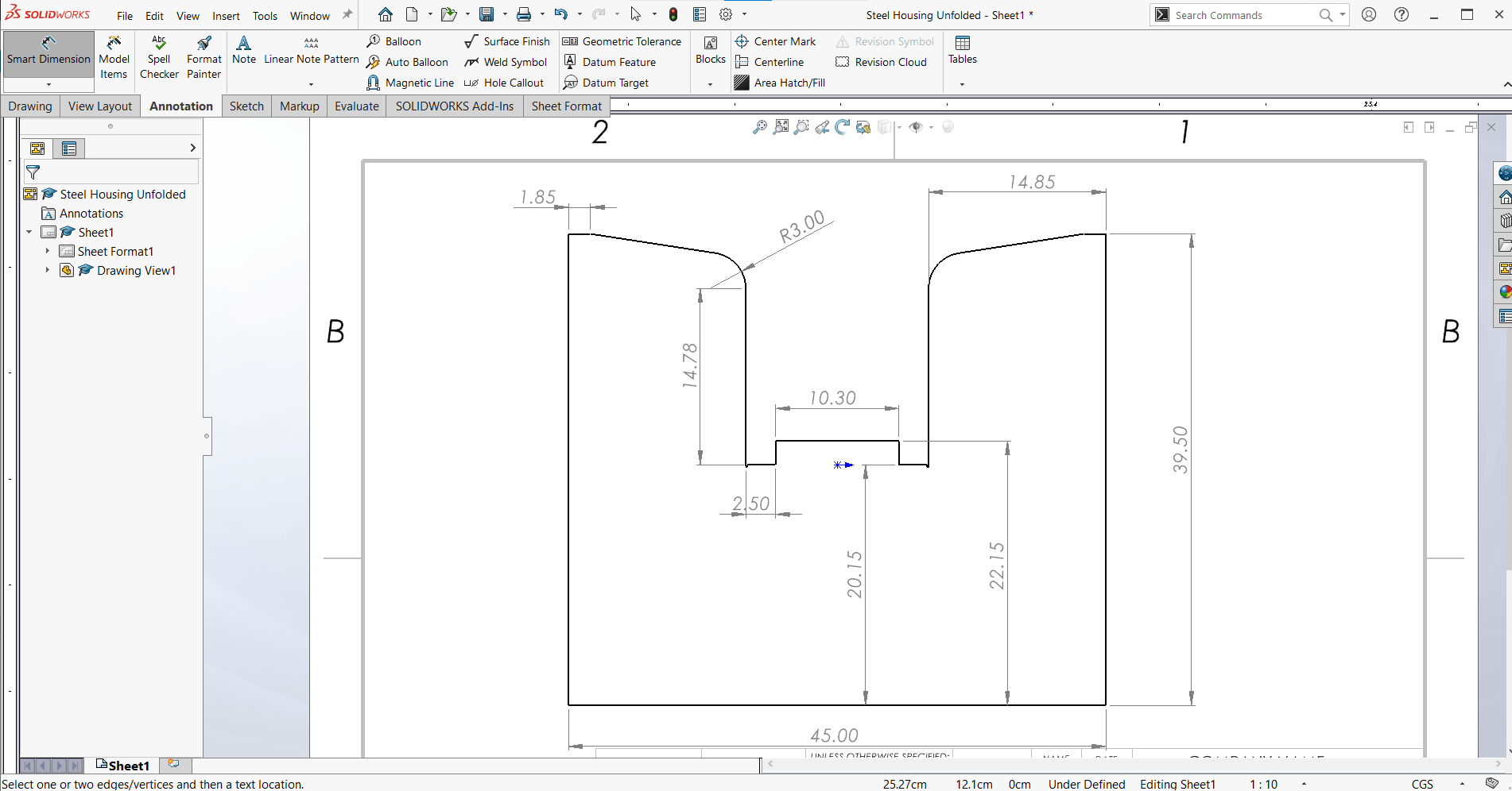
I began by using the Make a Drawing from Part function to generate simple drawings of my parts to make it easy to fabricate them. These are not formal engineering drawings, nor are they sufficient to make the parts using the drawings alone, but they were enough for me to get making.
Waste Not, Want Not
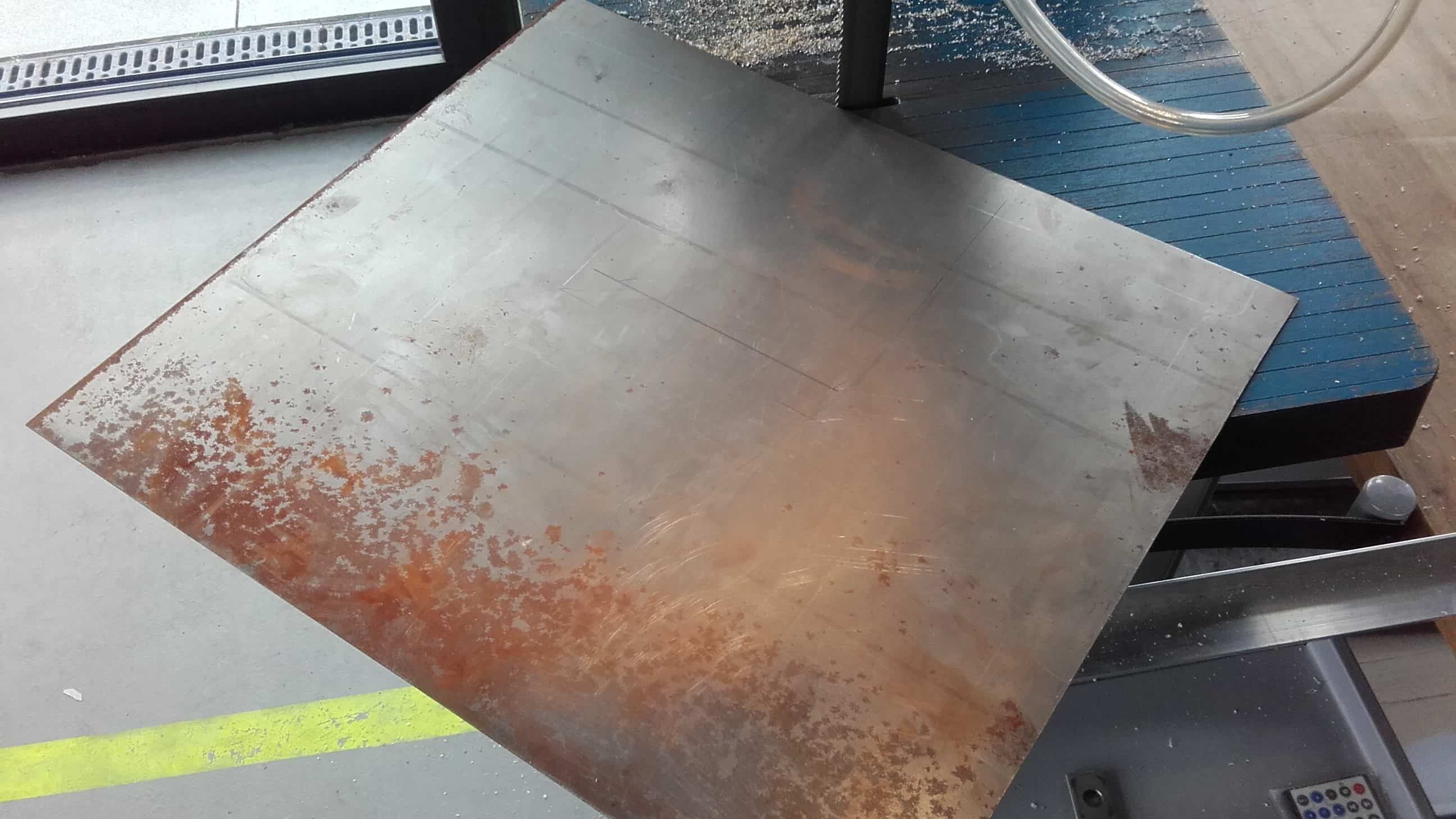
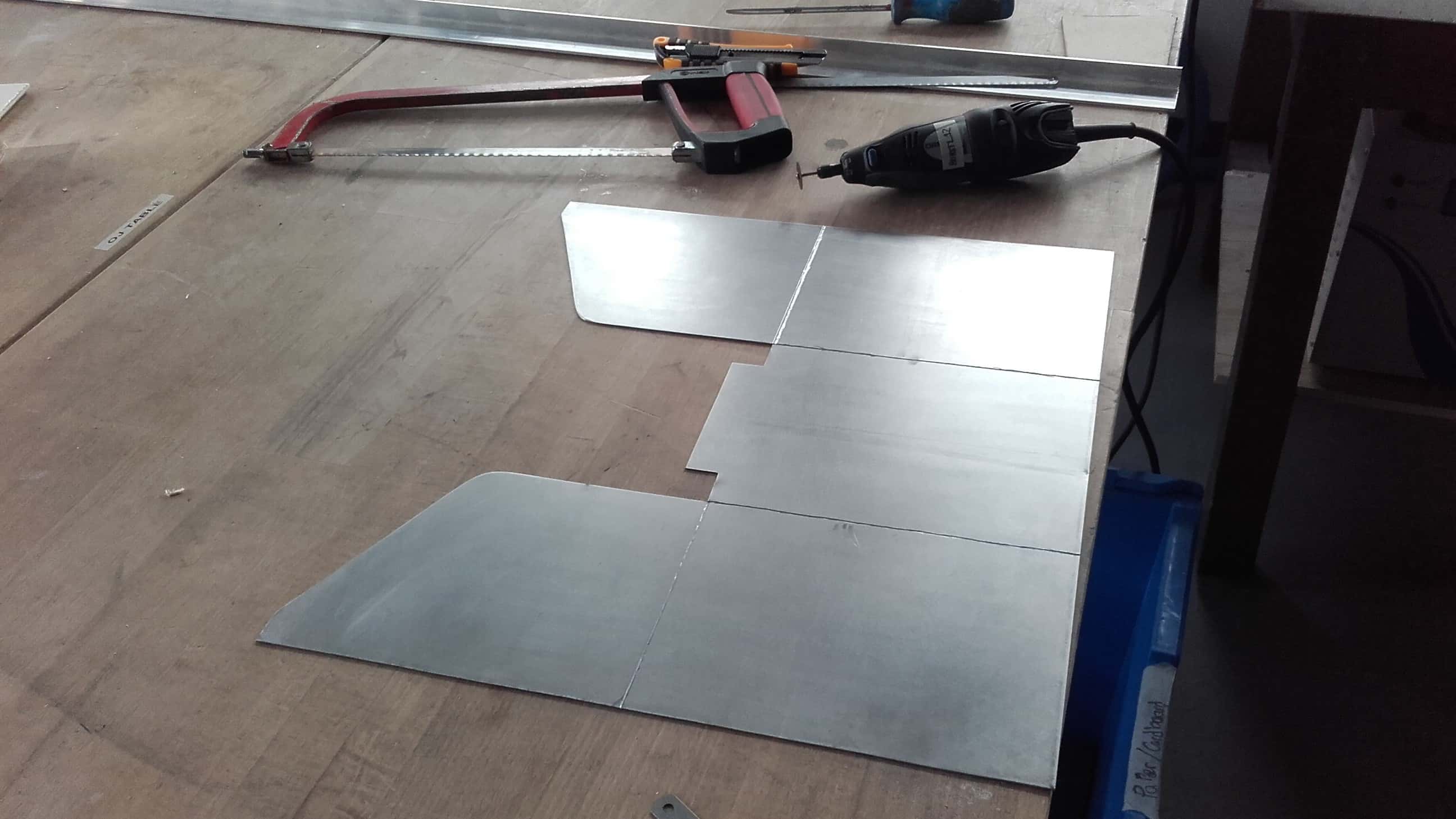
I found some 1 mm scrap metal in the lab. It was a little bent, and very rusty, but it was big enough and available, so I grabbed it and marked out all the straight cuts.
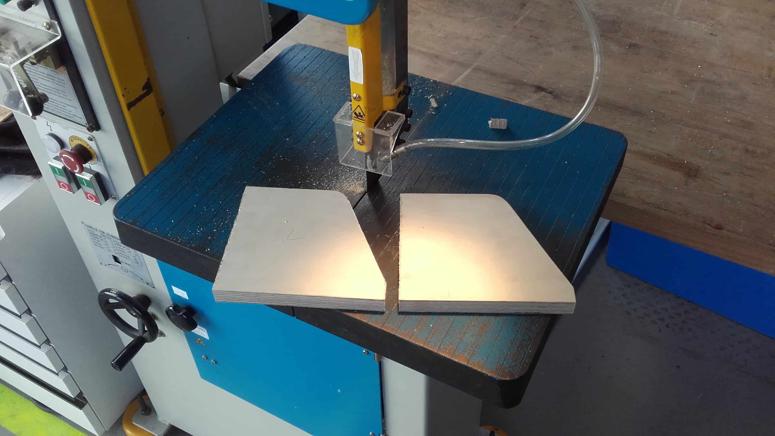
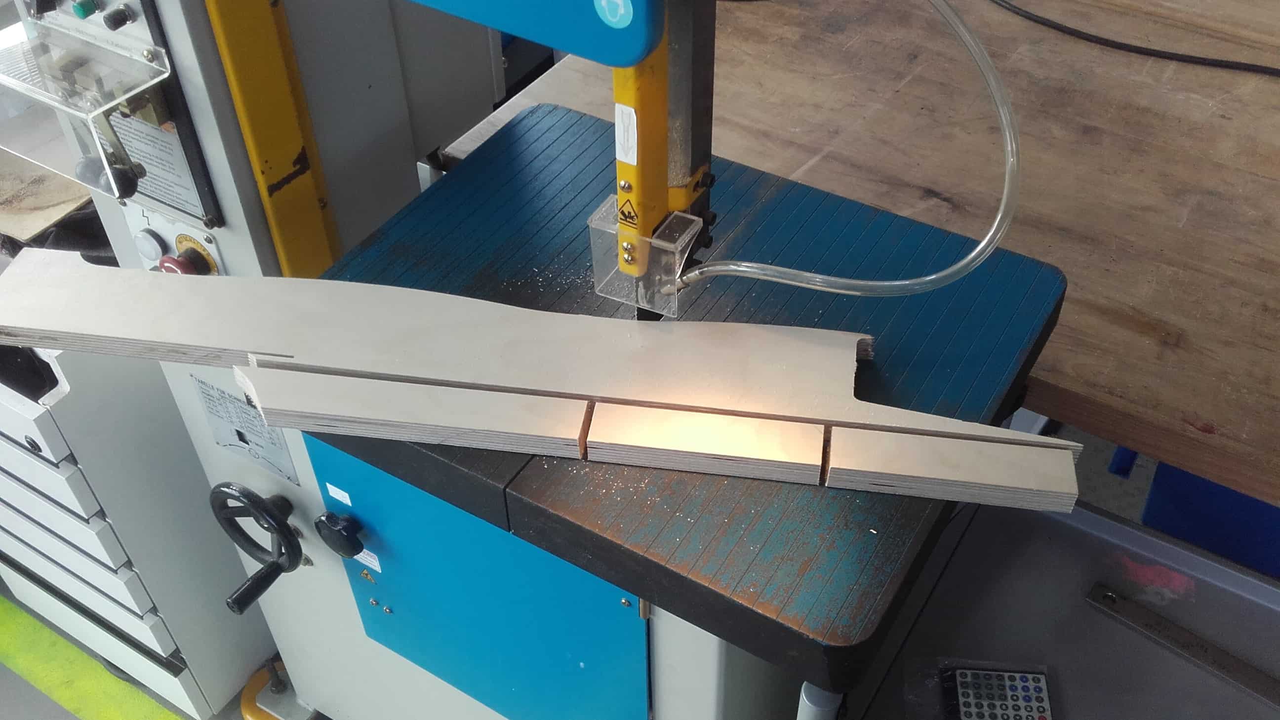
Cardboard Stencil
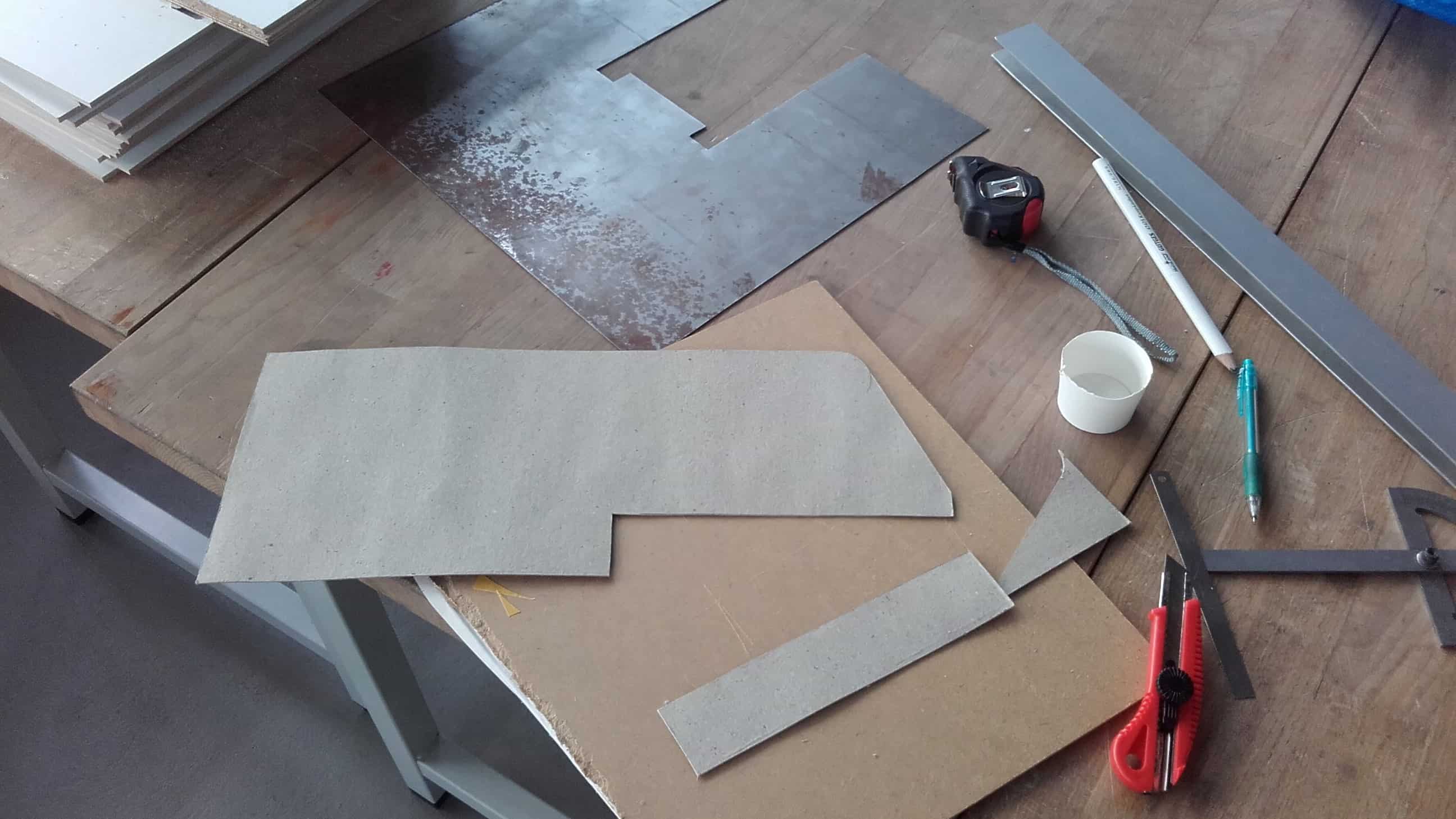
Then I cut the basic shape out on the bandsaw and made a cardboard stencil to transfer the more complicated geometry around the pin joint to the metal as well.
Cleaning Edges
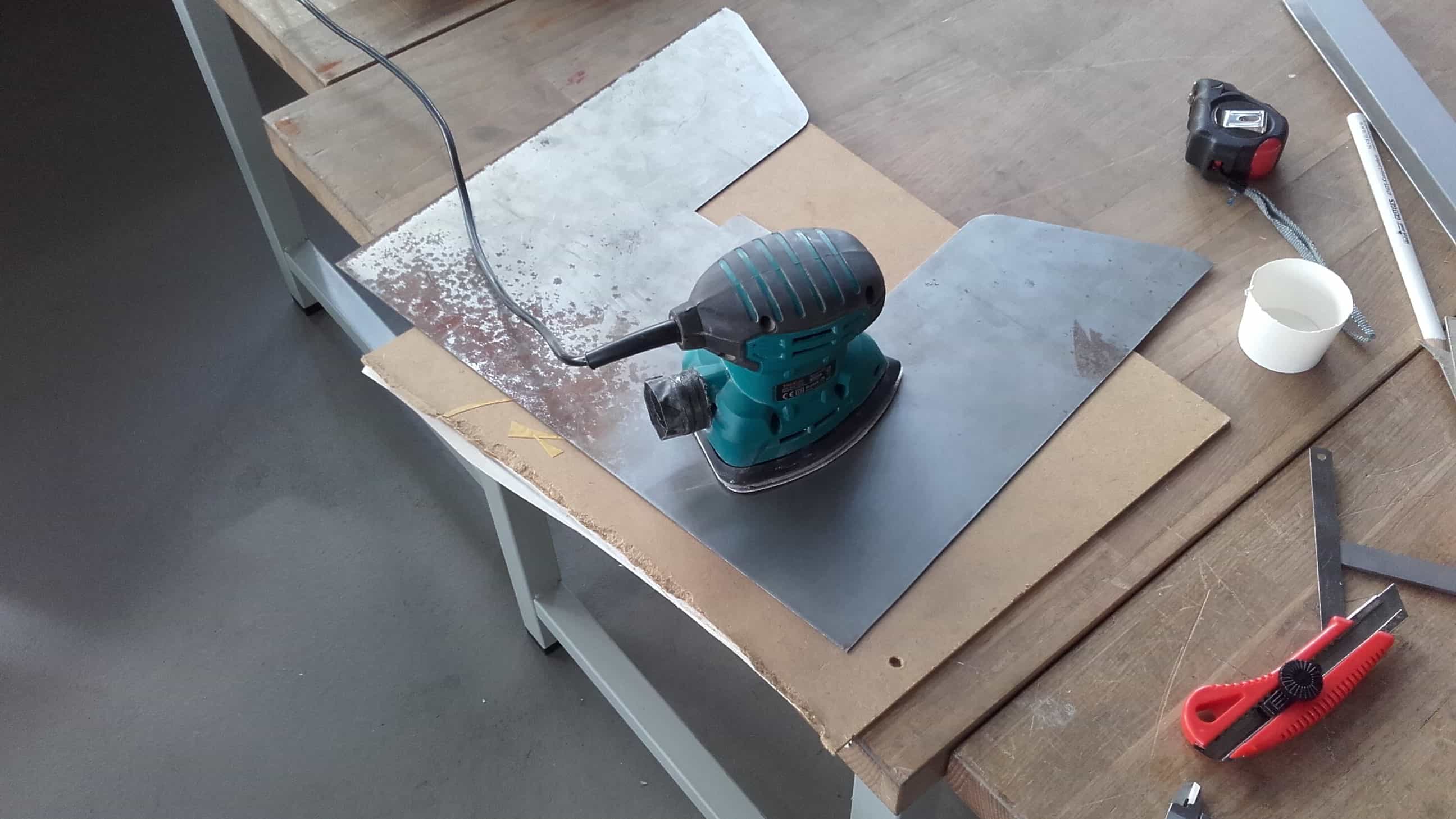
After cutting those out on the bandsaw as well, I used hand files to clean up the edges and I cleaned off all of the old rust using a palm sander.
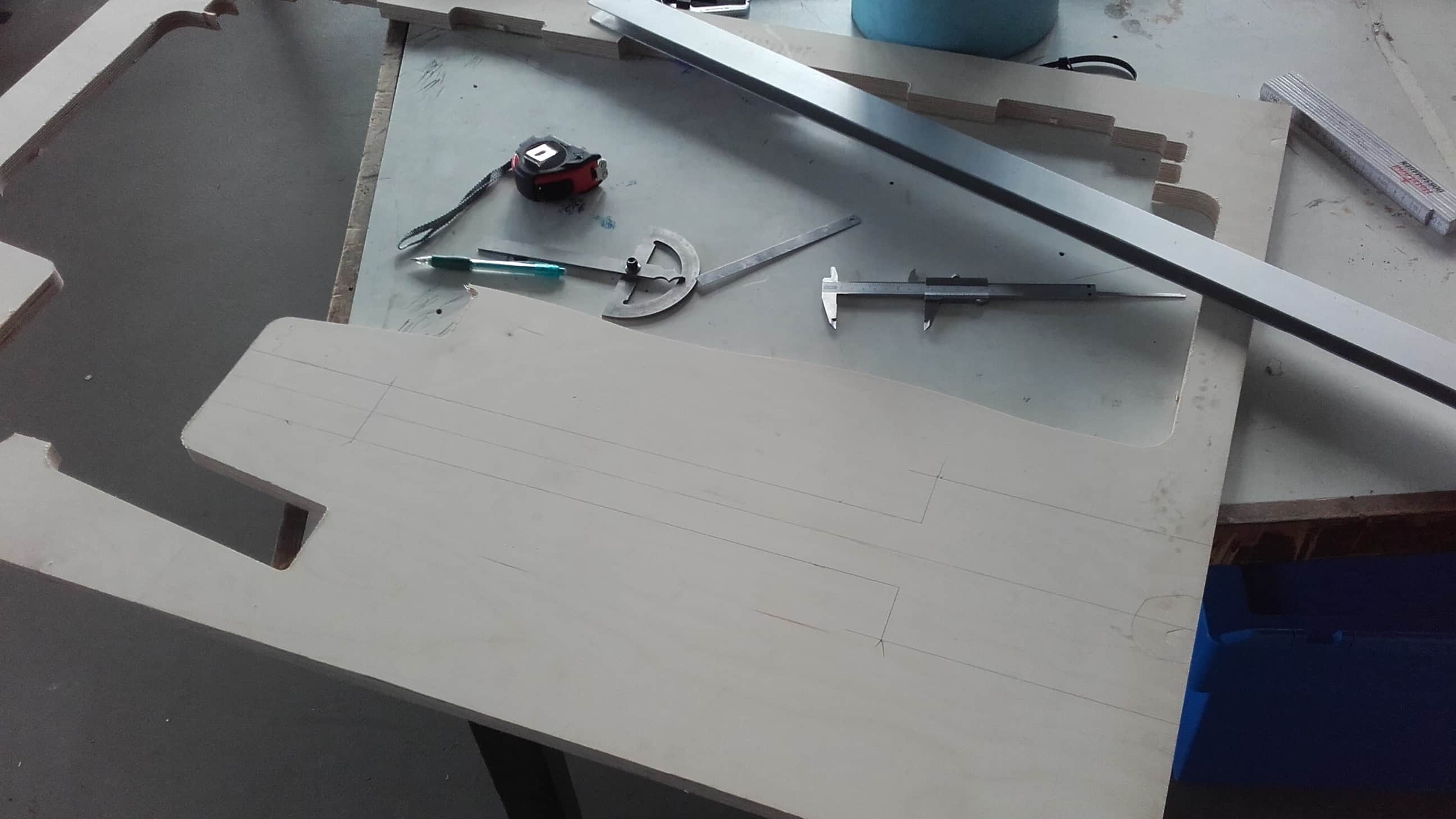
Scribing
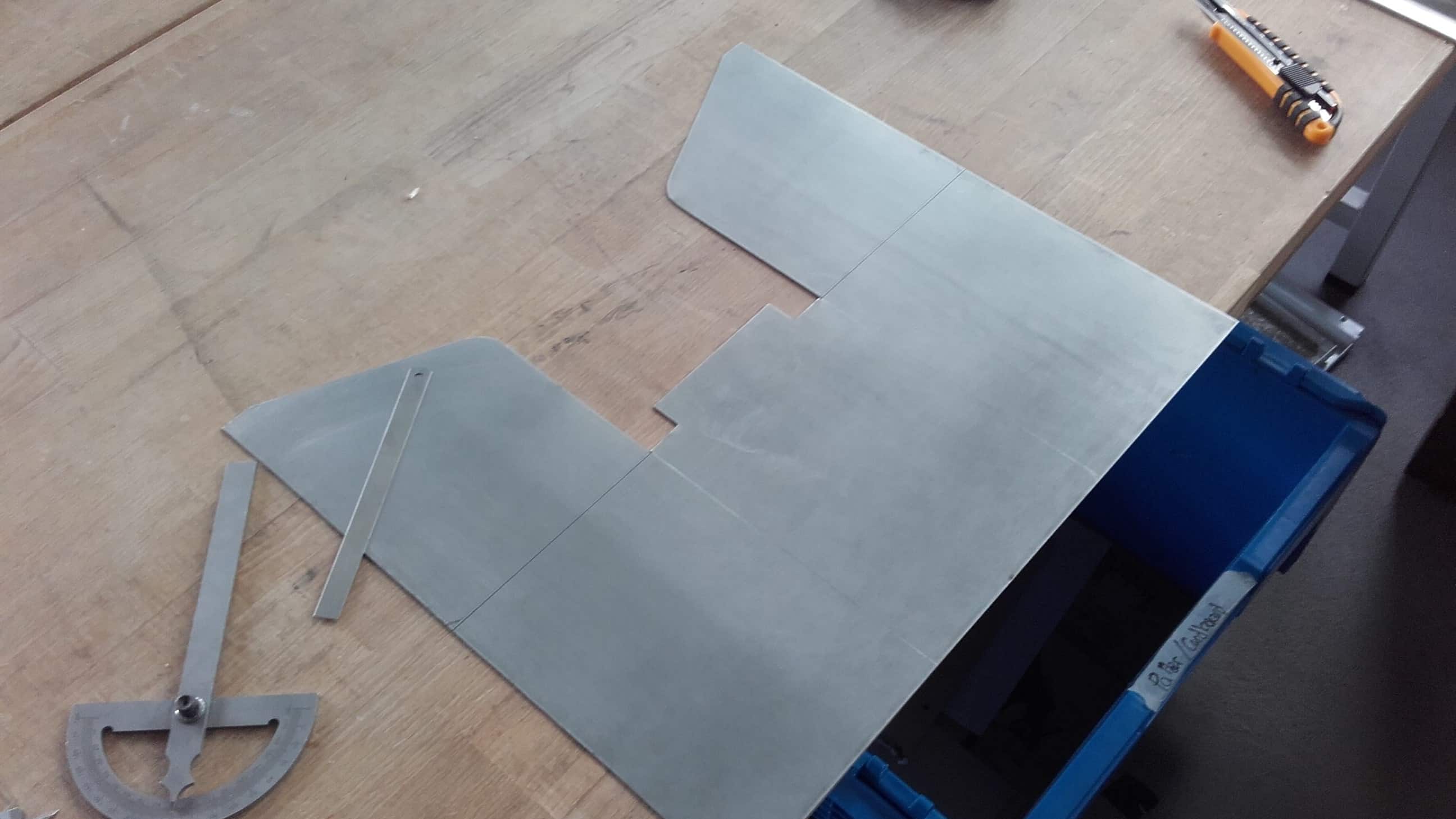
Finally the metal was the correct dimensions and looking good, so I carefully scribed out all of the lines where I would need bends to make the shape I wanted.
Bending Experiment
As I said before, metal bending is new to me, and we don't have a proper metal brake or any other bending equipment in our lab. I knew I would be tackling this job with nothing but clamps and willpower so I did a couple small experiments first.
Scoring with a Dremel
I got the best results when scoring the inside corner of a bend using a Dremel tool, so that is the method I chose to use for the real thing. With no guides or jigs set up for this job, it was a bit tedious to say the least. Anybody who has ever worked with a Dremel knows how they can get away from you, and I knew that would mean death for my bends, so I did this scoring very slowly and carefully. It wasn't perfect in the end, but it was the best I could do.
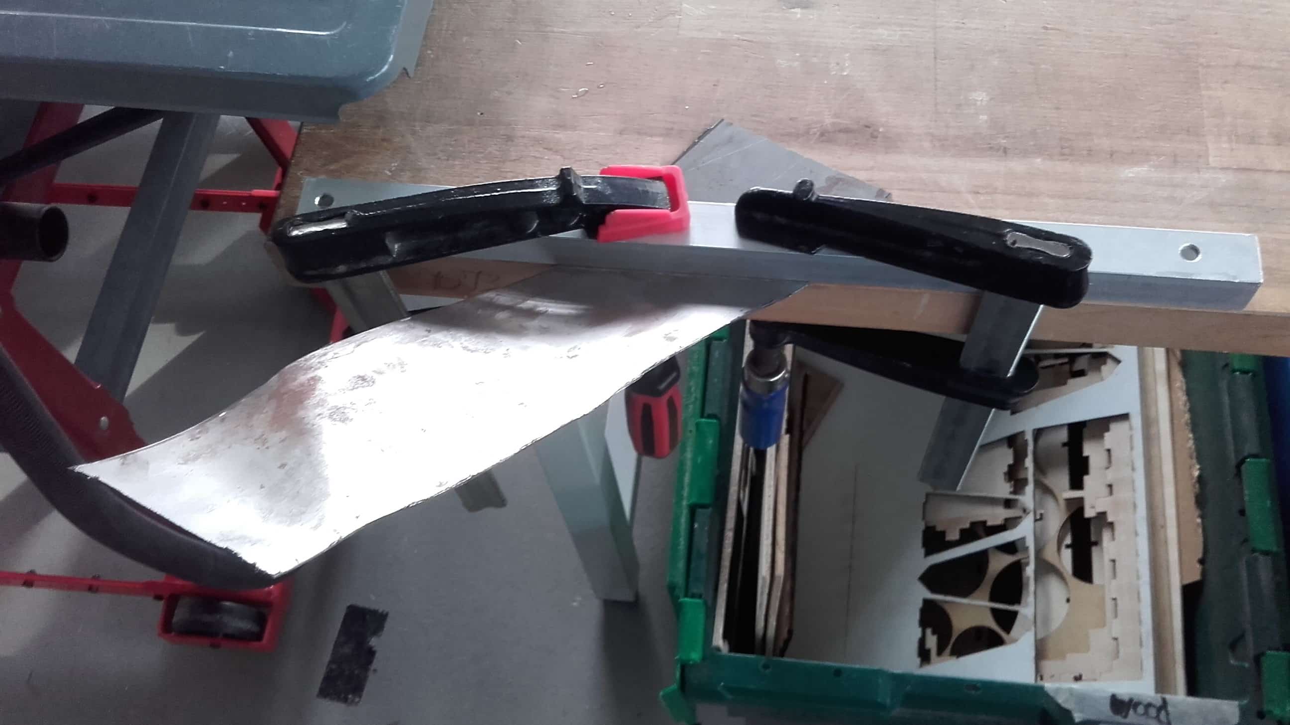
Bending Real Thing
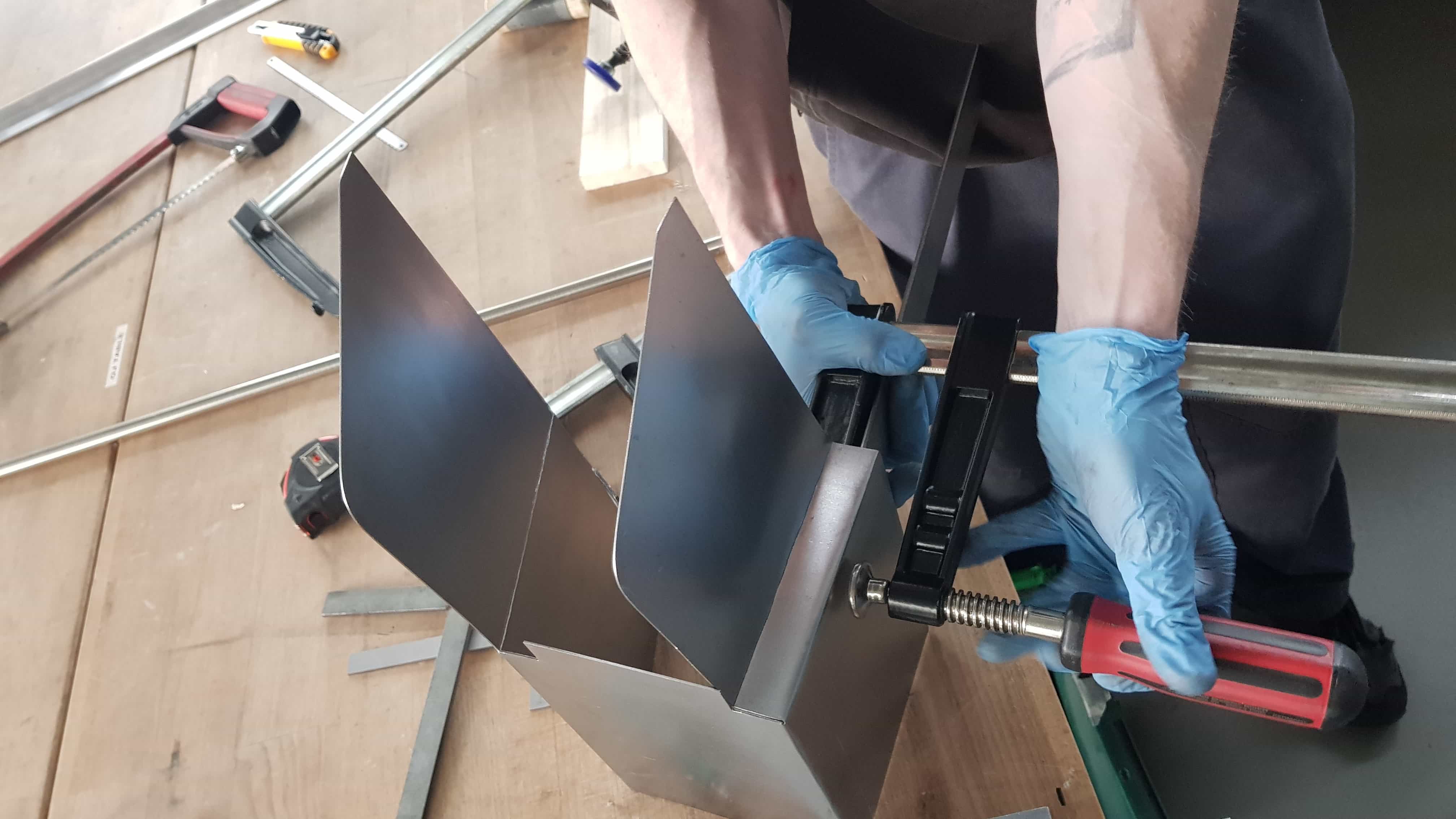
Then I very carefully started bending. This was a slow process with a lot of repositioning of clamps and bracing blocks. I also used pieces of angle iron and aluminum square tubing to assist in the bending, both for the square corners, as well as for keeping plane surfaces plane while bending.
More Scrap Recycling
Once the bending for the housing was completed, It was time to start cutting wood. I found some suitable scraps leftover from the Something Big project and marked out my cuts. It would have been easier to use new lumber, but I like the idea of this machine being made entirely out of reclaimed materials and spare parts laying around the lab.
More Cleaning
Then I started cutting. I cut most of the parts on the bandsaw, and then cleaned them up with either the palm sander, or the belt sander.
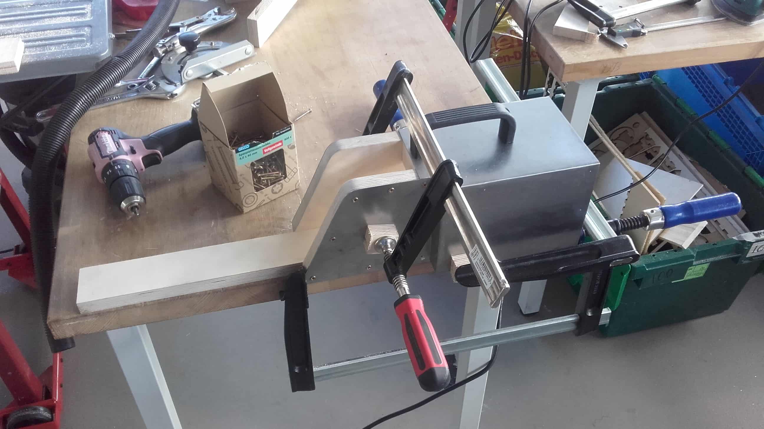
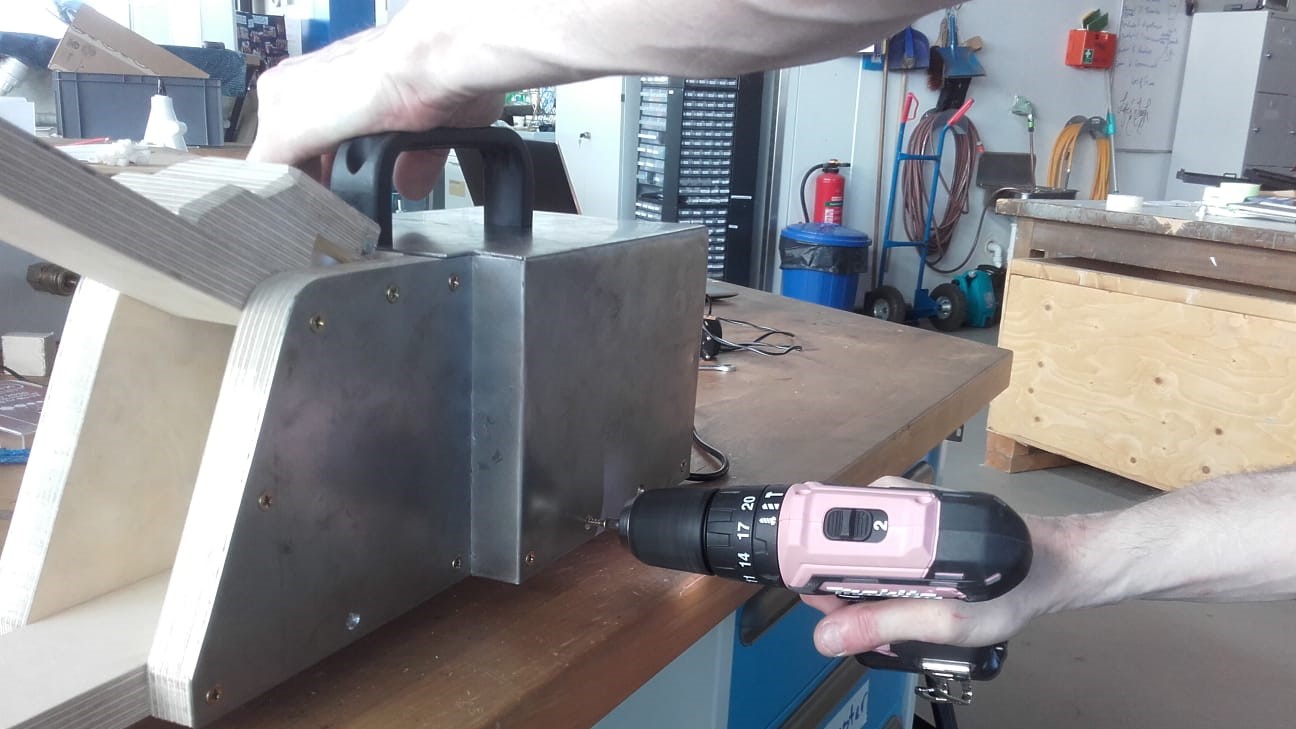
Clamping to Drill Holes
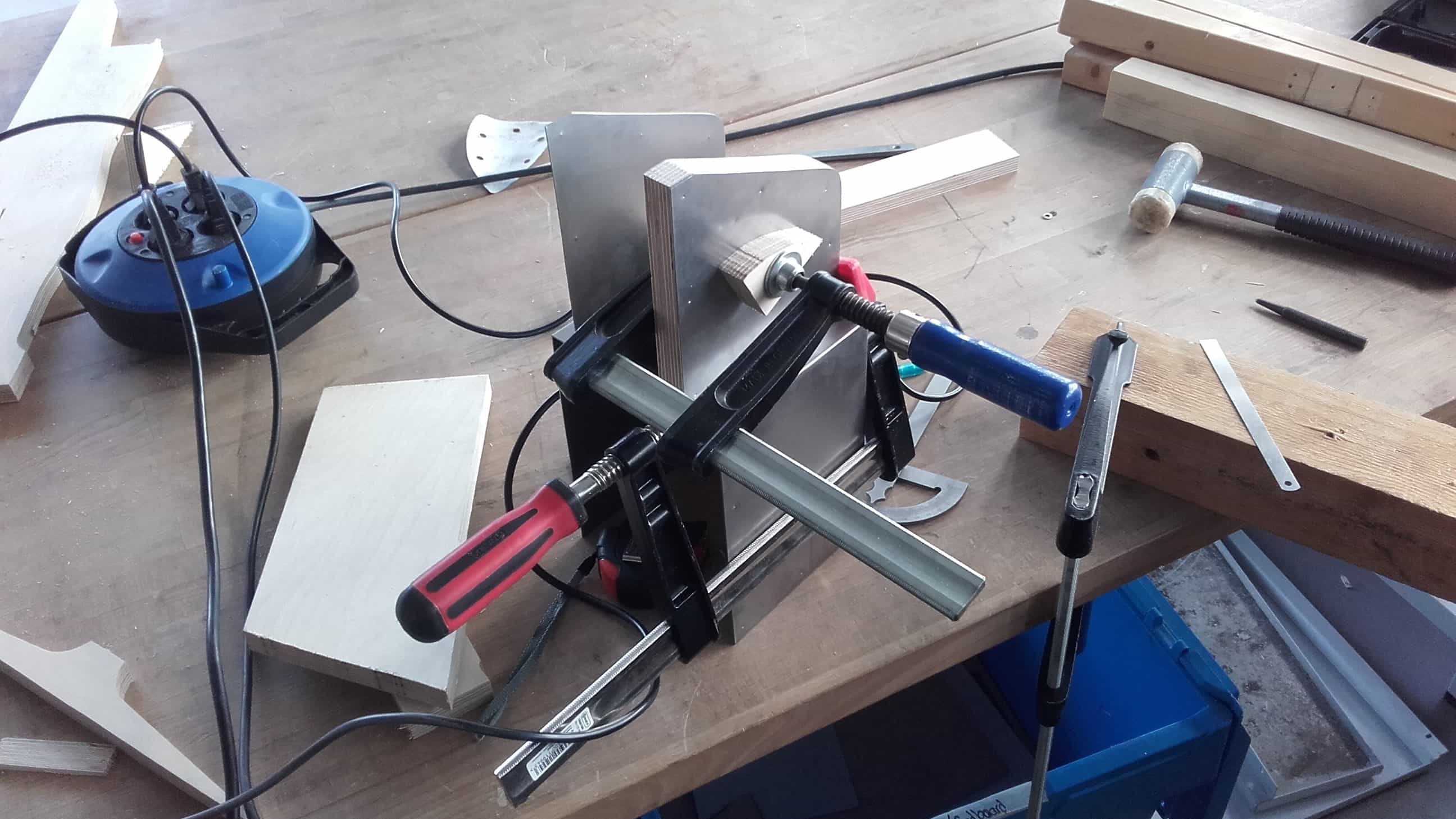
Then, using many clamping setups once again, I secured the parts where I wanted them so I could drill the holes for the bolts and screws that would eventually hold the device together.
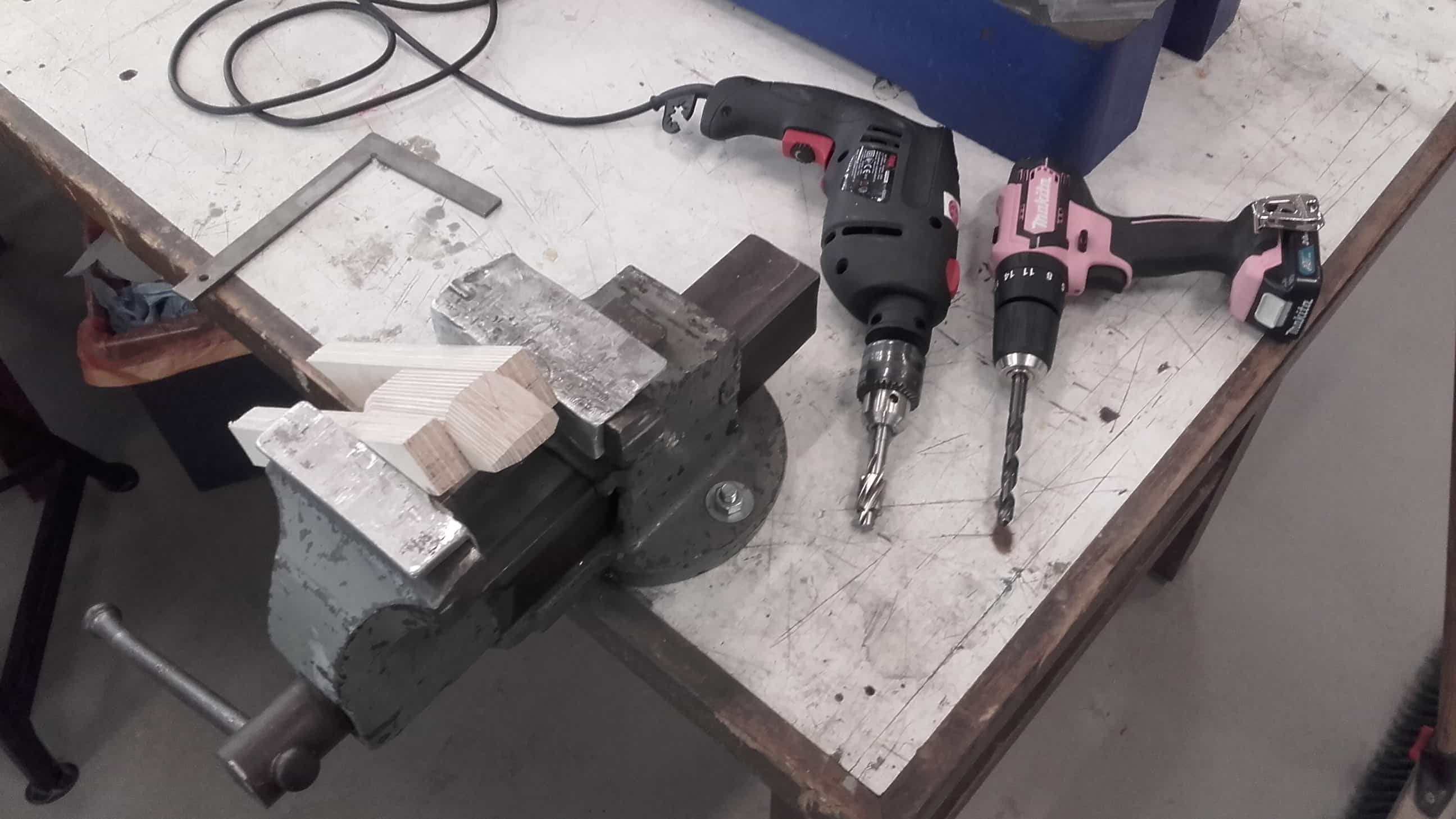
Drilling Holes
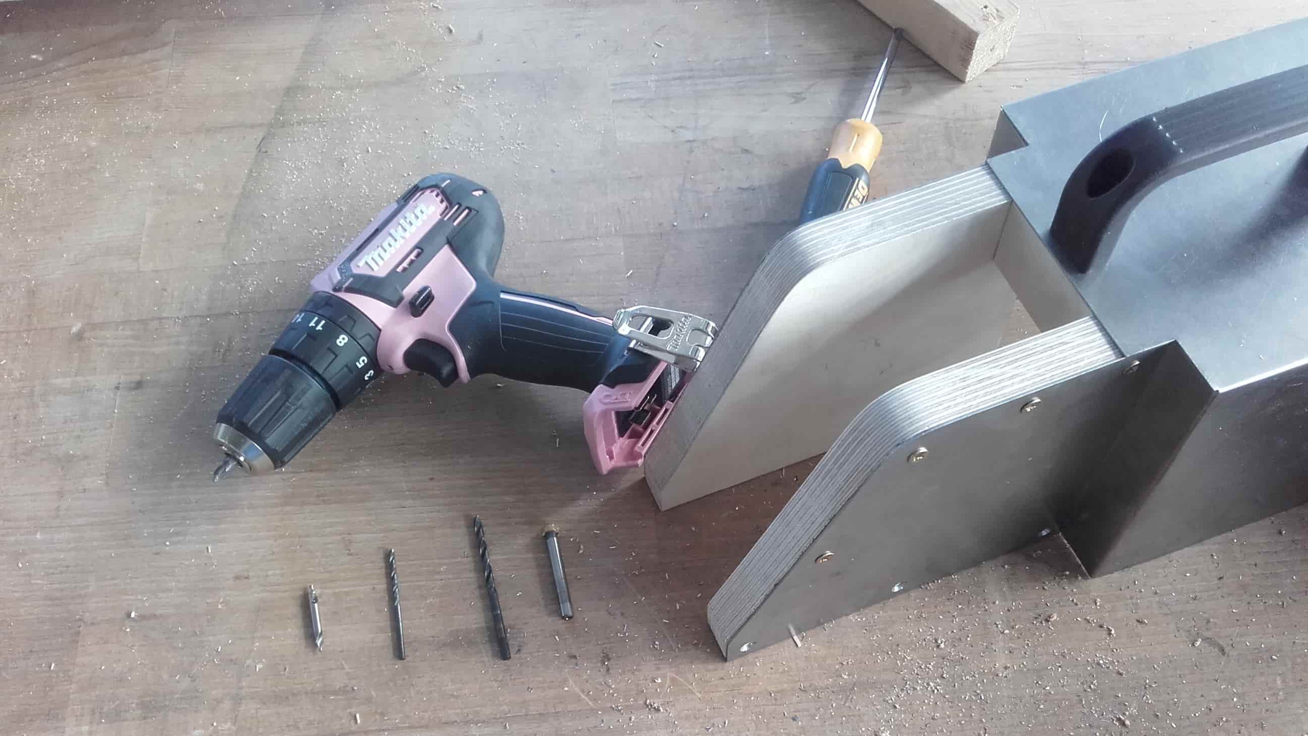
For every hole, I used a center finding bit to start the hole in the steel, then a 2.5 mm bit to drill the through hole into the wood. This was followed by a 4 mm bit only through the steel, and then a chamfering bit on the outside of the steel to allow room for the countersink on the screws. In the end, the screws fit really nicely, so I am glad I took the time to do the extra steps.
Sanding Edges
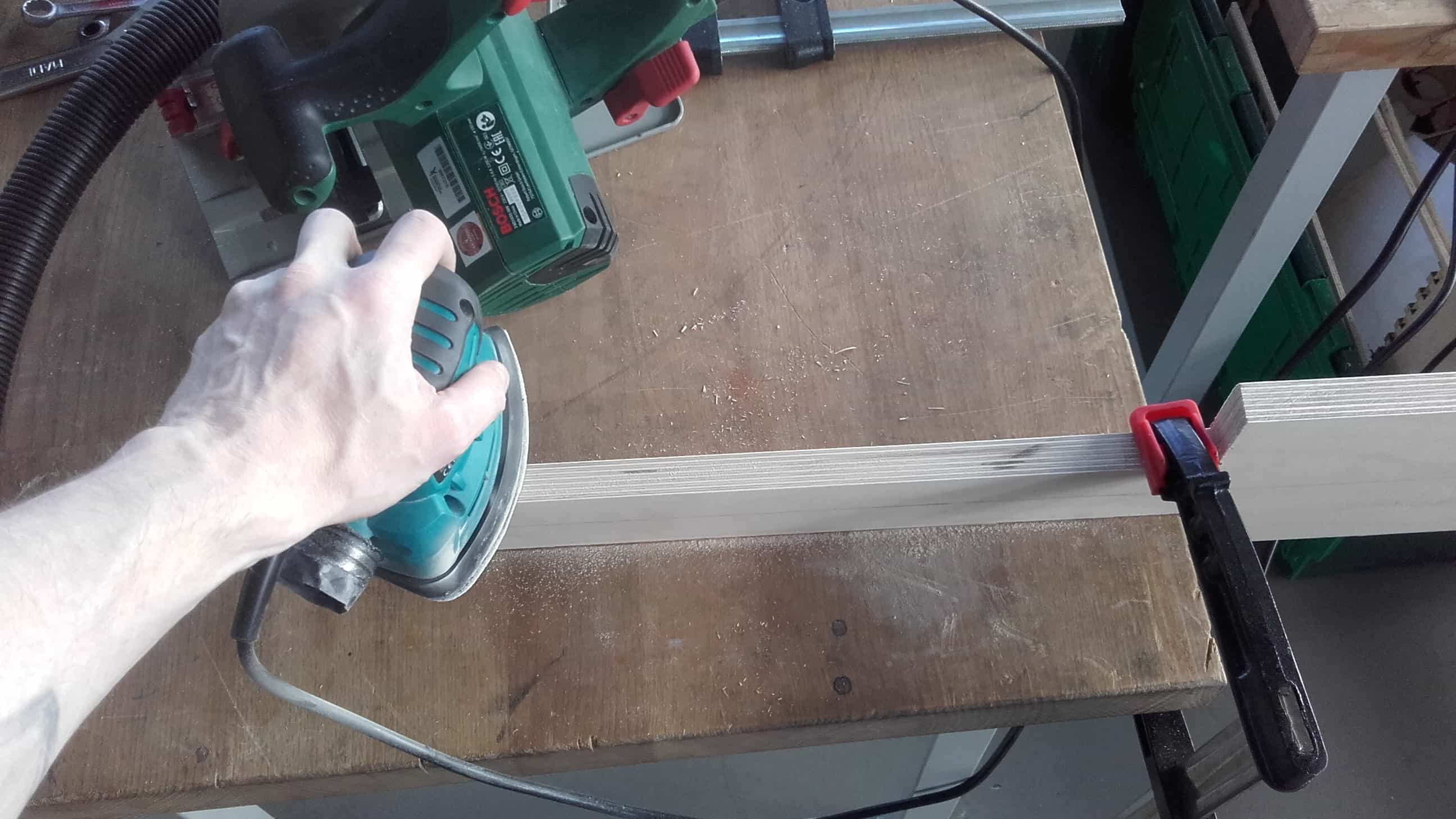
Finally, it was time to get all of the parts cleaned up for the test assembly. Once again, I used the palm sander to clean up the bandsaw cuts as well as any other manufacturing marks.
More Clamping for Mor Holes
Then I carefully aligned the parts and used clamps to hold them in place while I drilled the through holes in the wood. Once again, this took many setups and a lot of time.
Handle Outline
For the handle, I started by marking out the general shape of the two halves and then cut the pieces out on the bandsaw.
Glue Up
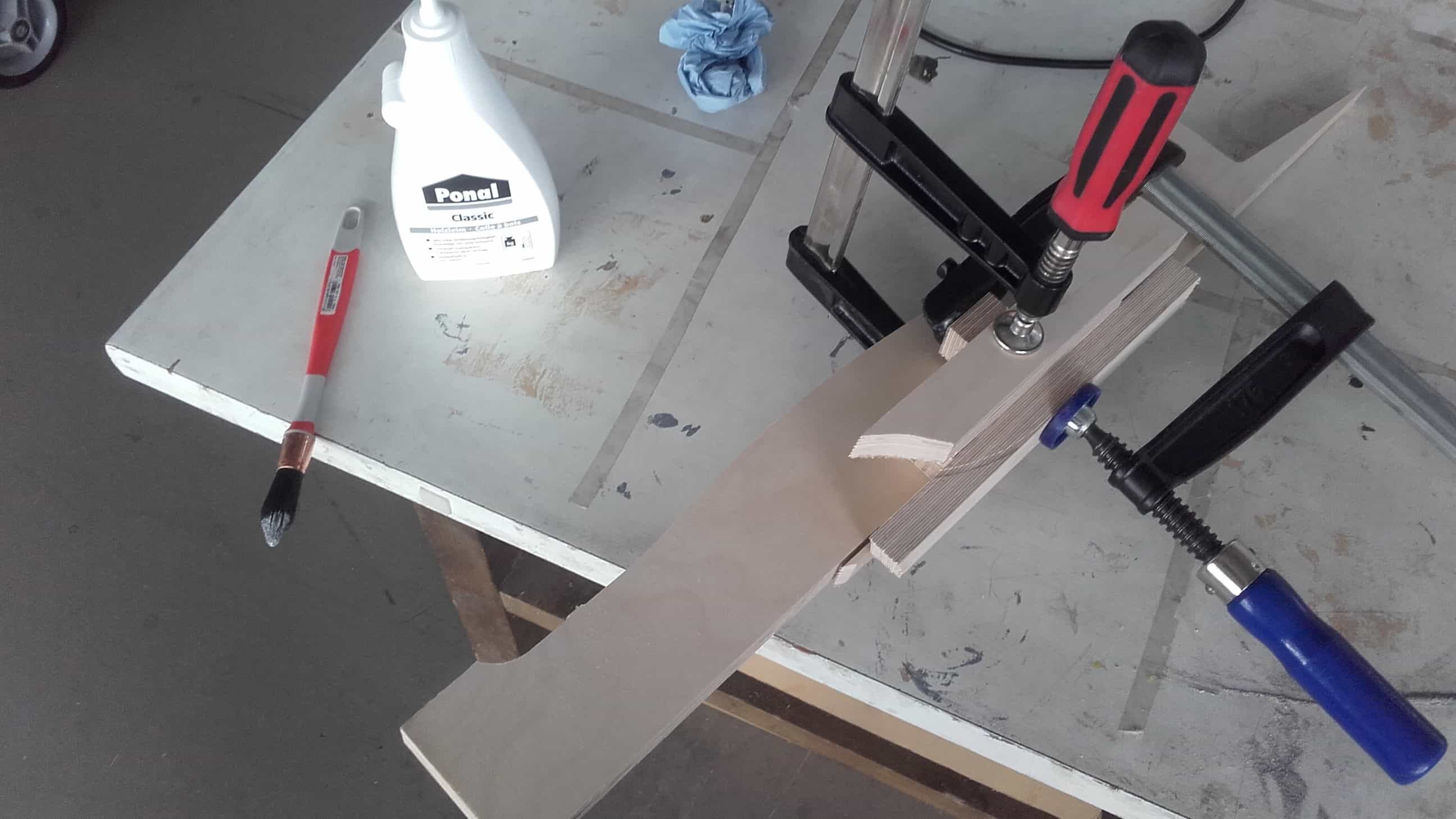
Then I glued the pieces together and sanded down the sides to clean up the bandsaw cuts.
Chamfers
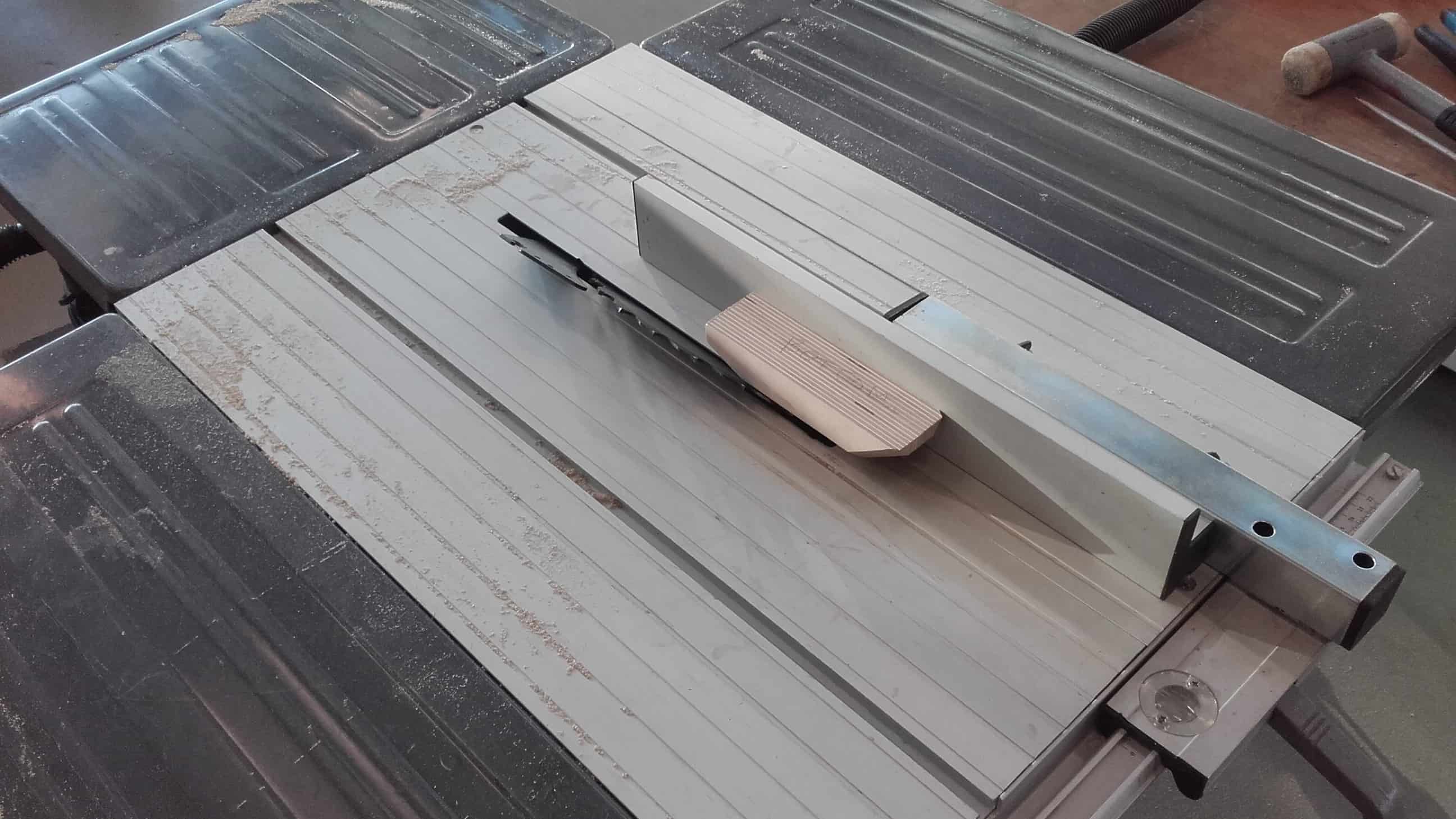
I used the table saw with a 45° angle to cut all the little chamfers.
Home for Pushbutton
And then I used a combination of a 10 mm drill bit and a counterbore bit to clear out the space for the pushbutton.
Pockets for Nuts and Bolts
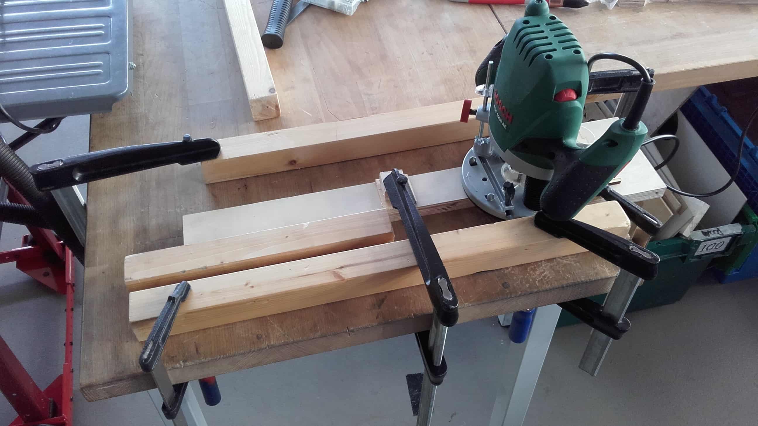
Then I used a router to hollow out a space for the linear actuator to fit, and to create a recess between the steel of the housing and the side panels for the nuts and bolts of the pin joints to reside.
Nearly Complete
Once the device was finally all assembled, it was time for testing the controls. Unfortunately the linear actuator extended too far on the very first stroke and broke the upper jaw.
Triage
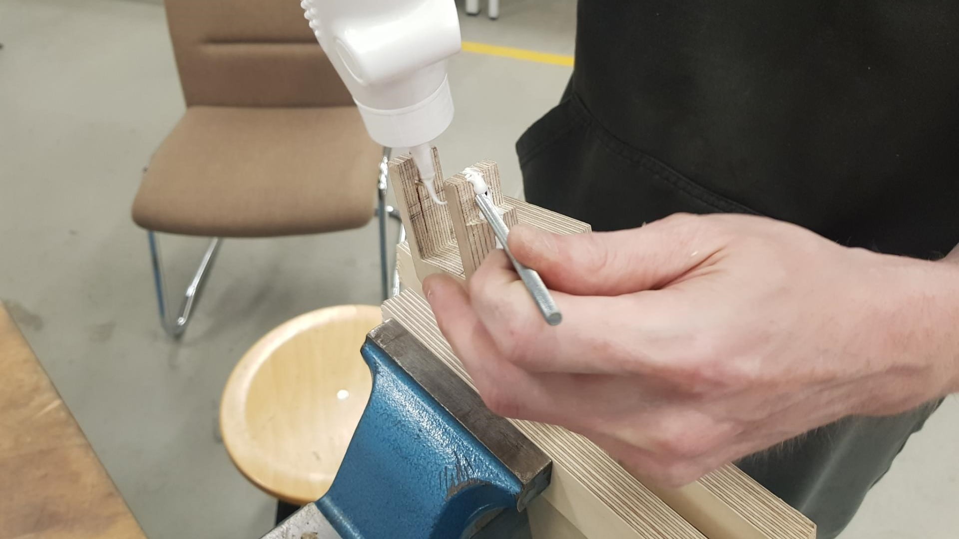
So I had to do some real time triage using wood glue and more clamps (the real heroes of this project).
Reassembly
When the glue was dry, I reassembled everything once again.
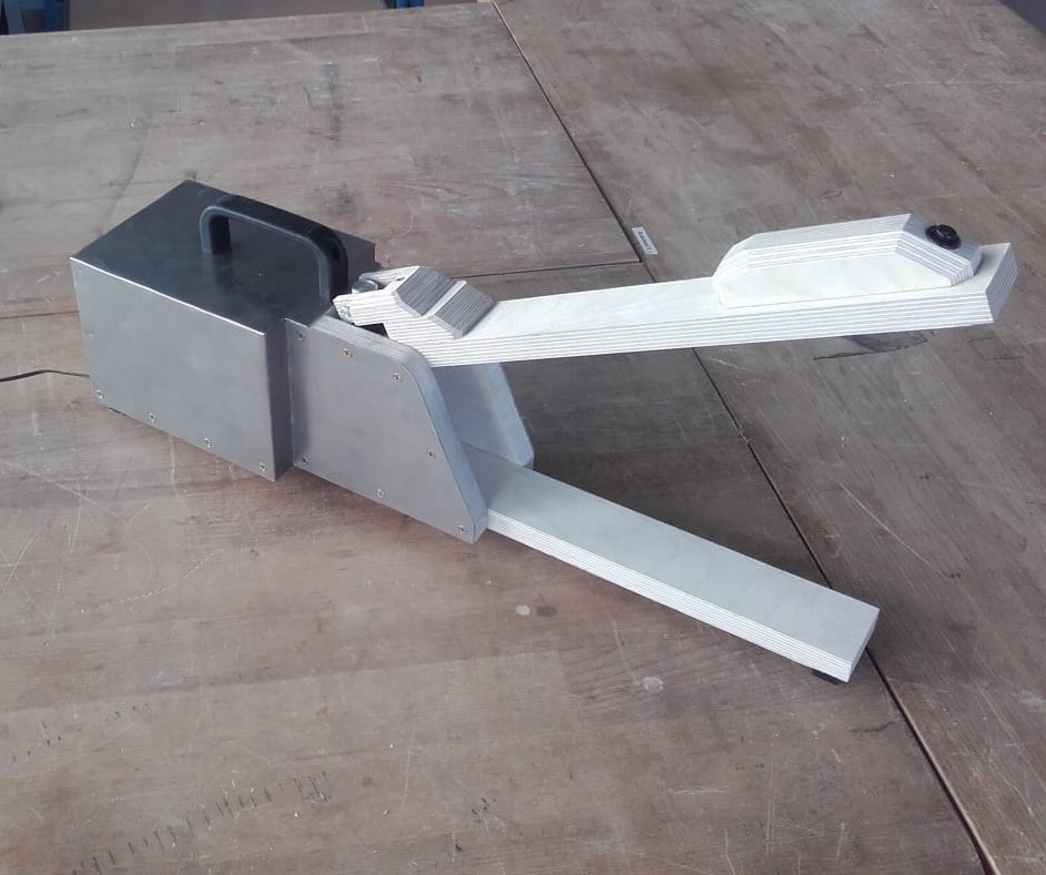
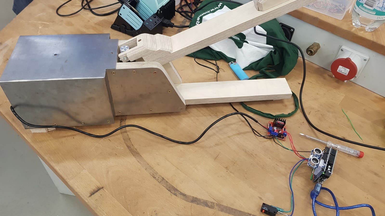
Front Side
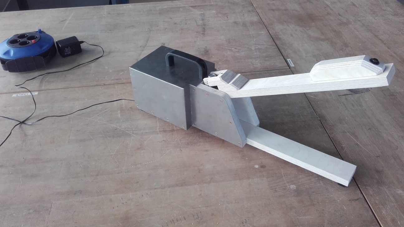
In the end, we had to come to terms with some major design changes, but overall I think my part came out ok.
Back Side
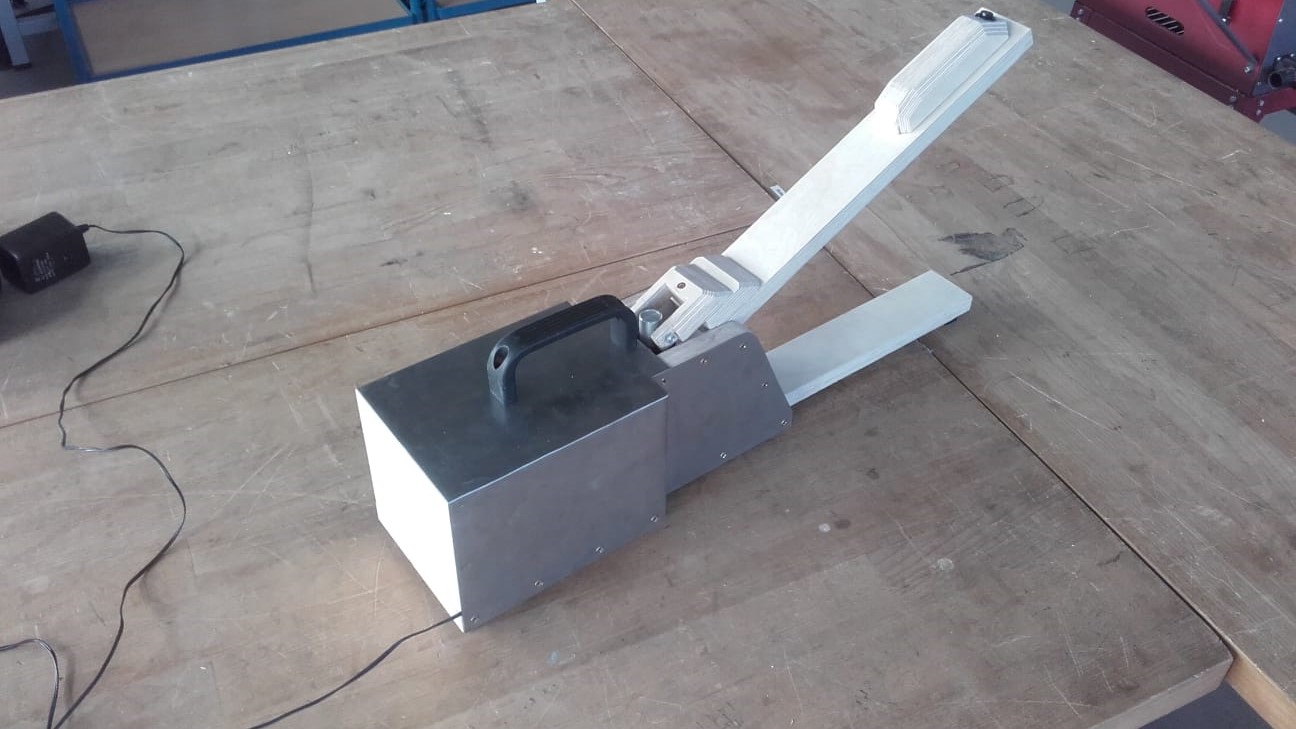
And all the electronics fit nicely in the back.
Part 2 (Leen's Part)
Task
Our task this time was to work with our fellow colleagues as a group and design a machine with a mechanism, actuate it, and automate it. Aaron suggested we build a simple spot welder as someone in a DIY video on Youtube did. We liked the idea and decided to add an automated "Safety Feature" to warn others when the welder is being operated. So my part of this group effort was to make this safety mechanism work.
A couple of changed plans later, we ended up making our lab's very own Fartigator 3000 :D. It is, as Neil Gershenfeld so nicely put it, "A Thing That Does A Thing". And although my technical contribution remained as planned, the purpose of the bubble maker now is to make farts, be it locally produced ones, or remotely actuated.
Hubbly-Bubbly
What You Need for My Part of the Machine
Hero Shots


Proof of Concept
The bubble blower feature gets activated once the mechanism is actuated and Fartigator 3000 opens his mouth. It is remotely controlled and is to be placed either in his main body or somewhere else in the workshop.
All for Science
Before investing time in a major design, we had to learn the secret recipe of how to make bubbles. Since I wanted to build the bubble blowing mechanism from scratch, I wanted to know how best to design the bubbles ring. This resulted in Aaron and I having to do some experimenting.
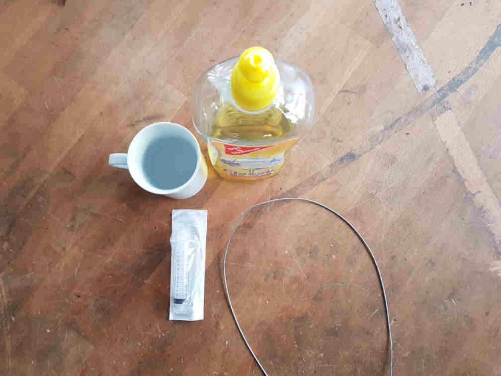
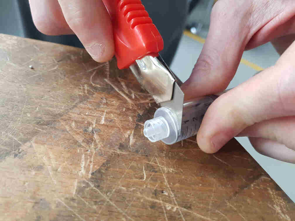
We wanted to use a syringe for our soap container and automatically protrude and retract the bubble ring that would be attached to the rubber seal of the syringe plunger. For that we had to sacrifice the syringe head.
Next came the bubble testing. We started out with a Bowden cable we found in the lab.
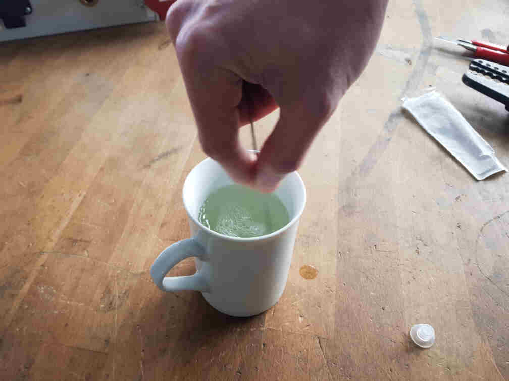
It proved a lot harder than anticipated to make bubbles, so we tried different sizes of rings, as well as some zip ties. Still had no satisfactory results, though.
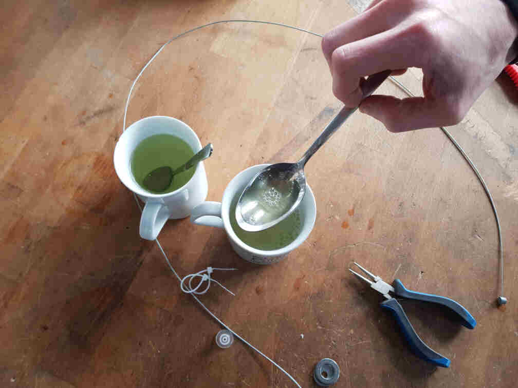
So we decided not to re-invent the wheel, and I went to a nearby shop and bought a pair of somethings :).

Getting Bubbles to Work
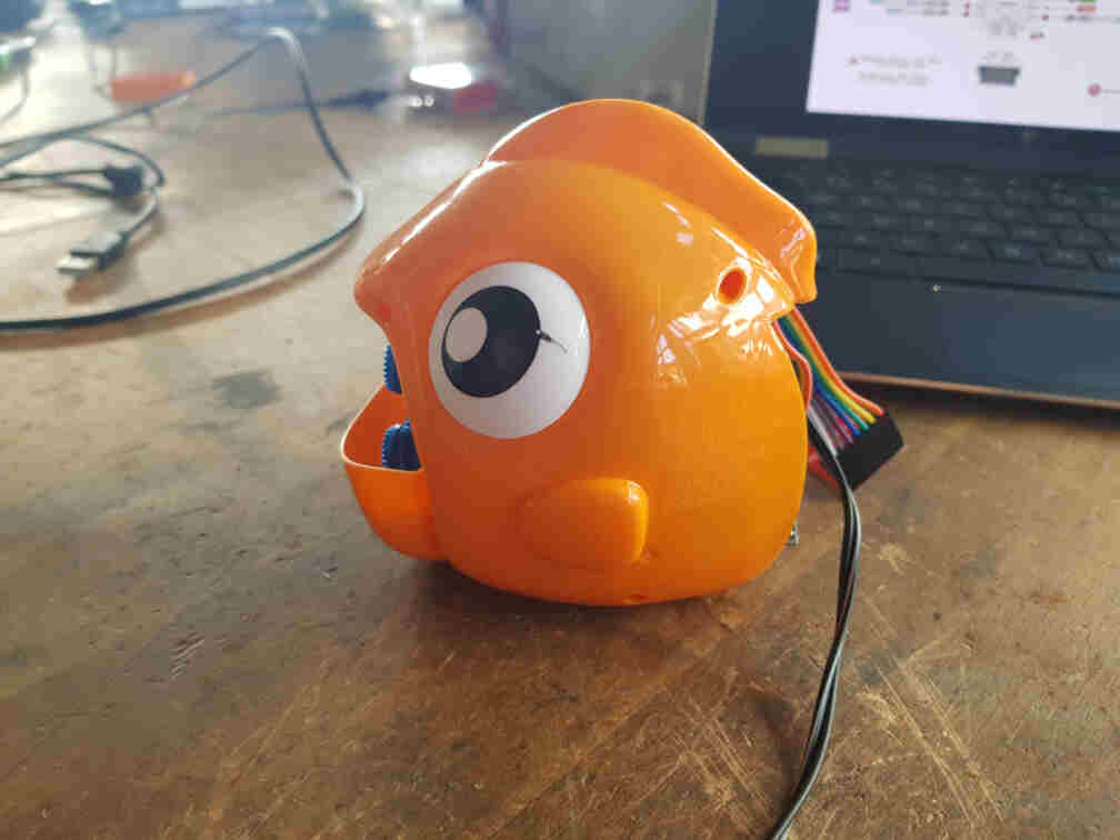
I chose to work on the fish and set out to convert it from a manually operated machine to an automated one.
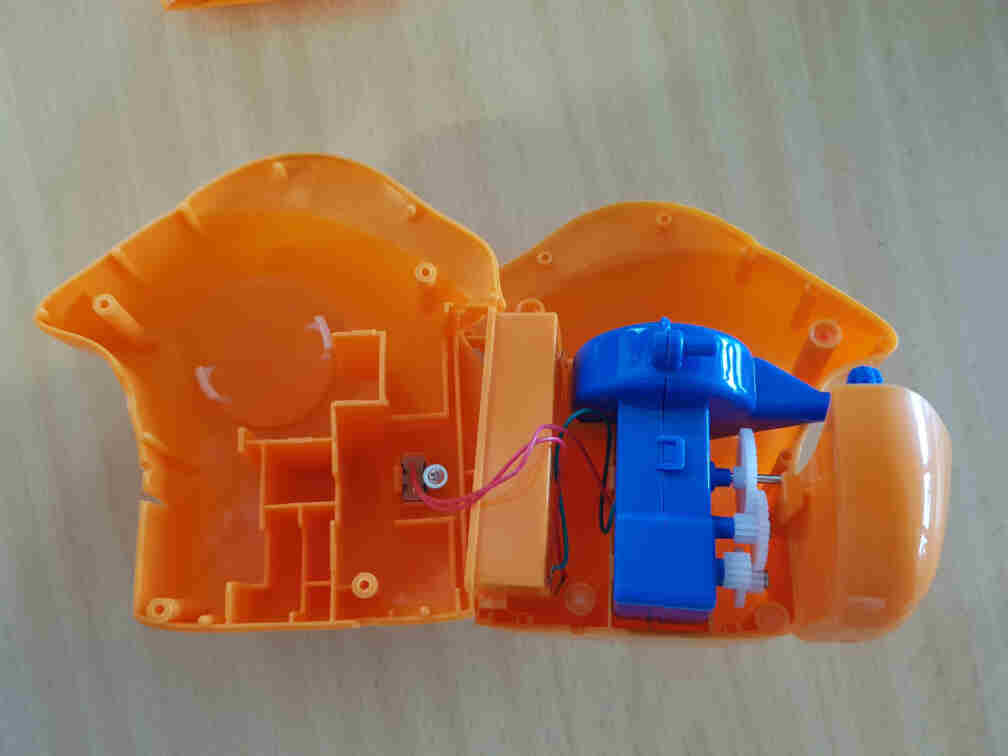
Opening It Up
My first step was to open up one of the bubble makers and see what I can do with it. I went for the fish one, and as it turned out, it was a pretty simple design. A switch was connected to one of the battery terminals and the DC motor, and the DC motor was used via gears to operate the air fan and the bubble rings rotating wheel.
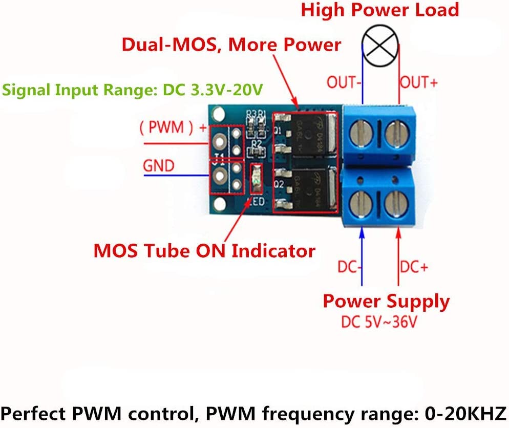
I then measured the motor's current consumption to help me pick which MOSFET to use to interface it with the microcontroller.
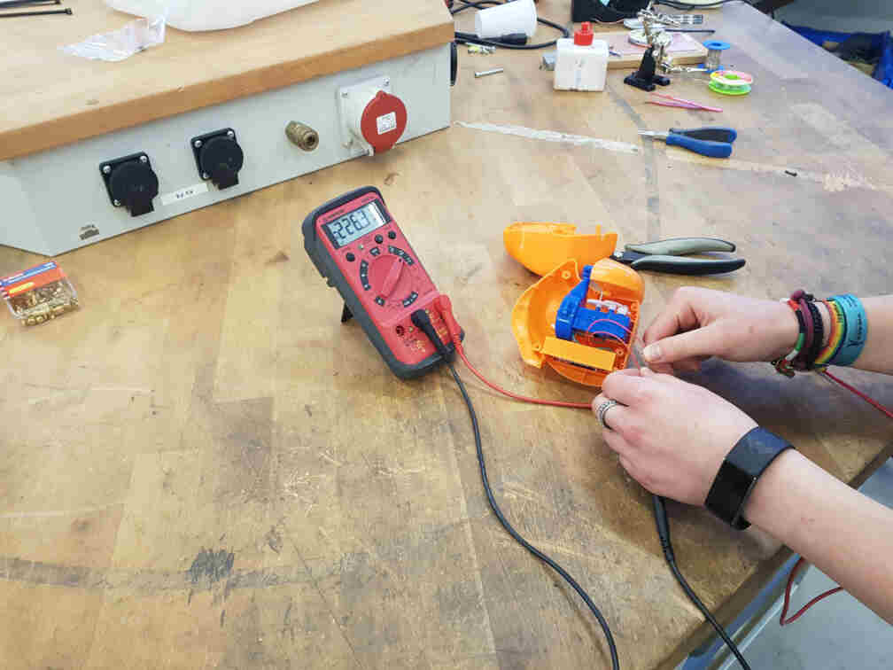
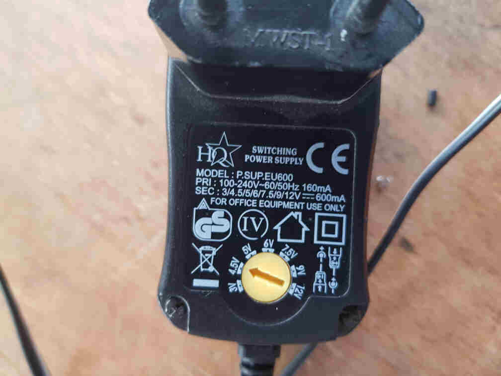
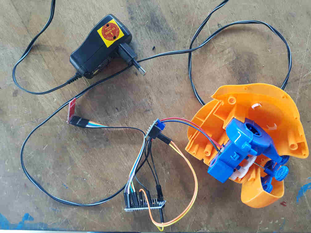
After I found out that one of the MOSFET breakout boards we have in the lab works, I connected it to the motor and used a power supply to test it. After that was successful, I looked through the lab for a transformer to supply the motor and microcontroller with enough power and found one.
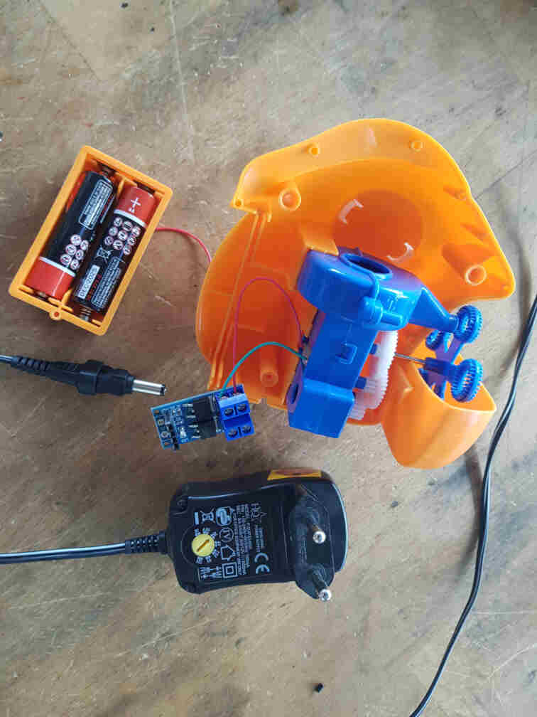
I turned the knob to 4.5 volts as a compromise between the arduino (5V) and the bubble maker motor (3V) because I didn't want it to turn that fast and didn't want to complicate the circuitry by adding a voltage regulator.
I then needed to attach the microcontroller pin headers to the transformer's cable and the DC+/- MOSFET terminals.
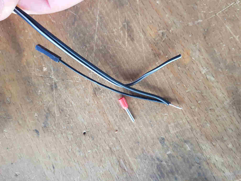
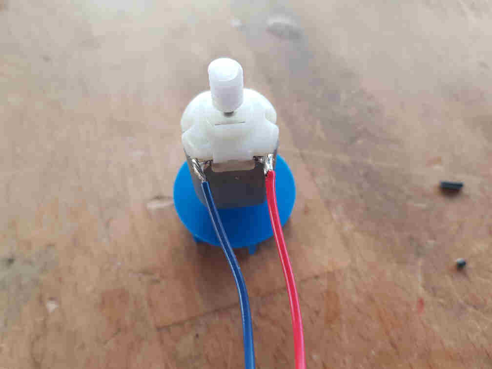
And I replaced the motor wires with more durable ones and connected them to the OUT+/- MOSFET terminals.
The full connection for the bubble receiver side then became as follows:
| Arduino Nano | nRF24L01 | MOSFET |
|---|---|---|
| Pin 3.3V | Pin VCC | - |
| Pin GND | Pin GND | Pin GND |
| Pin 5 | - | Pin TRIG/PWM |
| Pin 7 | Pin CE | - |
| Pin 8 | Pin CSN | - |
| Pin 11 | Pin MOSI | - |
| Pin 12 | Pin MISO | - |
| Pin 3 | Pin SCK | - |
Programming The Microcontroller
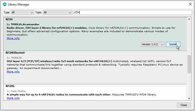
Before I began writing the code part, I had to install the radio transceiver arduino library RF24 by TMRh20 and Avamader.
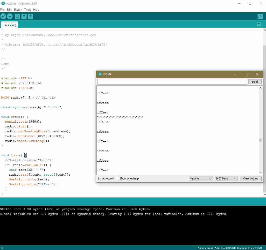
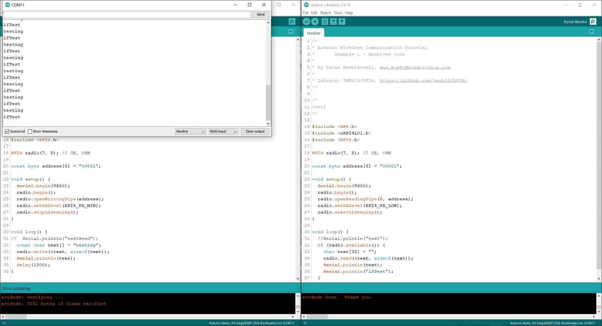
I then connected the second transceiver to the other Arduino Nano board to test the communication codes I got from Dejan Nedelkovski's page. I experimented with the signal strength between RF24_PA_MIN and RF24_PA_HIGH, and added some test lines to the receiver side for debugging with the Serial Monitor.
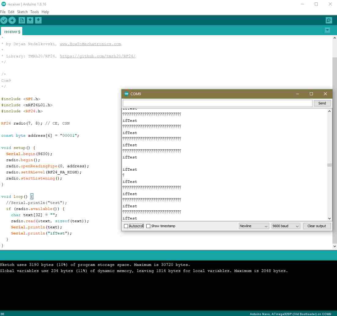
Although I double and triple checked my code and connections, I was getting no signals or undefined characters (picture on the left). I relocated my setup and tried my code again, and I was getting rather more undefined characters than no signal (picture on the right). I spent even further time trying to figure out what was causing this problem.
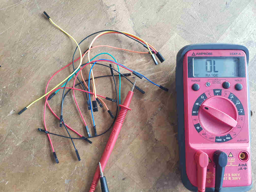
Until I started suspecting the actual connections between the modules, because I could not think of any other reason that would make more sense. So I set up to test the jumper wires with a multimeter.
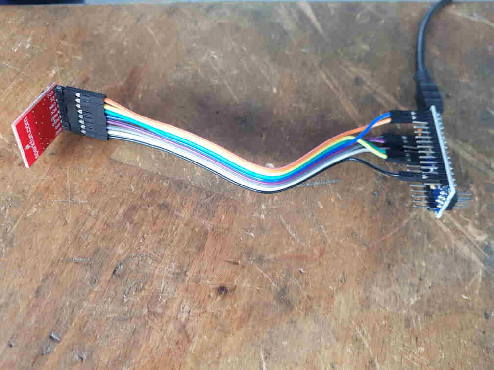
And what do you know, the wires were actually the cause of the problem! So I got all connections some new jumper wires...
And it worked like a treat! The debugging line I added to make sure that the code was going into the if (radio.available()) statement was showing up on the Serial Monitor.
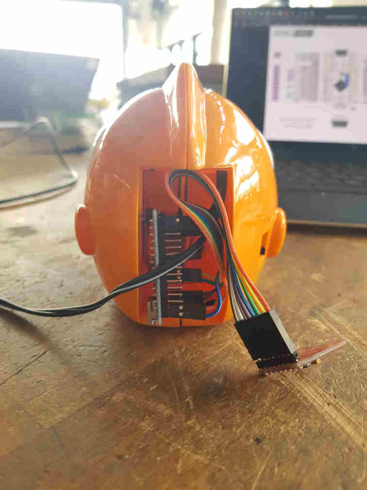
After that I hooked everything up on the receiver side.
And then I wrote a test code that allows the receiver to control the MOSFET state according to the incoming message from the sender.
After all hardware was working as intended, I put everything together and closed the bubble maker.
Last step was then to adapt the sender code so that is can be integrated into the actuation mechanism on our machine. It is supposed to listen to a high signal on an input pin (connected to an output pin og the mechanism microcontroller) and send the message to the bubble machine receiver to turn on the bubbles.
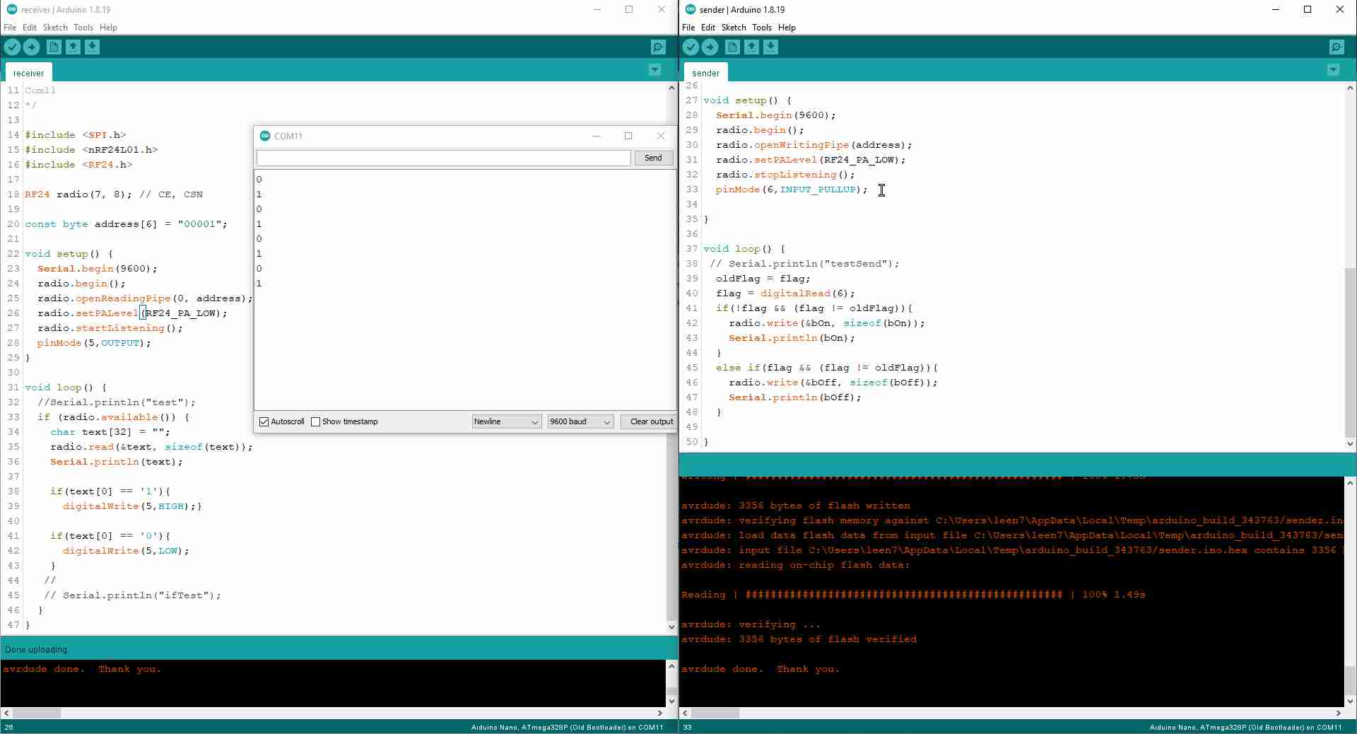
And here is the full code for both microcontrollers, the sender and the receiver.
Part 3 (Roland's Part)
Machine design week was a horrible kerfuffle for our group. In the beginning of machine design week (or rather: the two weeks including Easter break) I was suffering from a Covid infection which meant 10 days of isolation and no lab access for me. When I was slowly feeling better, my 1- and 3-year ones came down with Covid too - meaning no daycare, but Daddy-daycare only. At the same time, we kind of decided to build a spot welder and started preparations.
System Setup
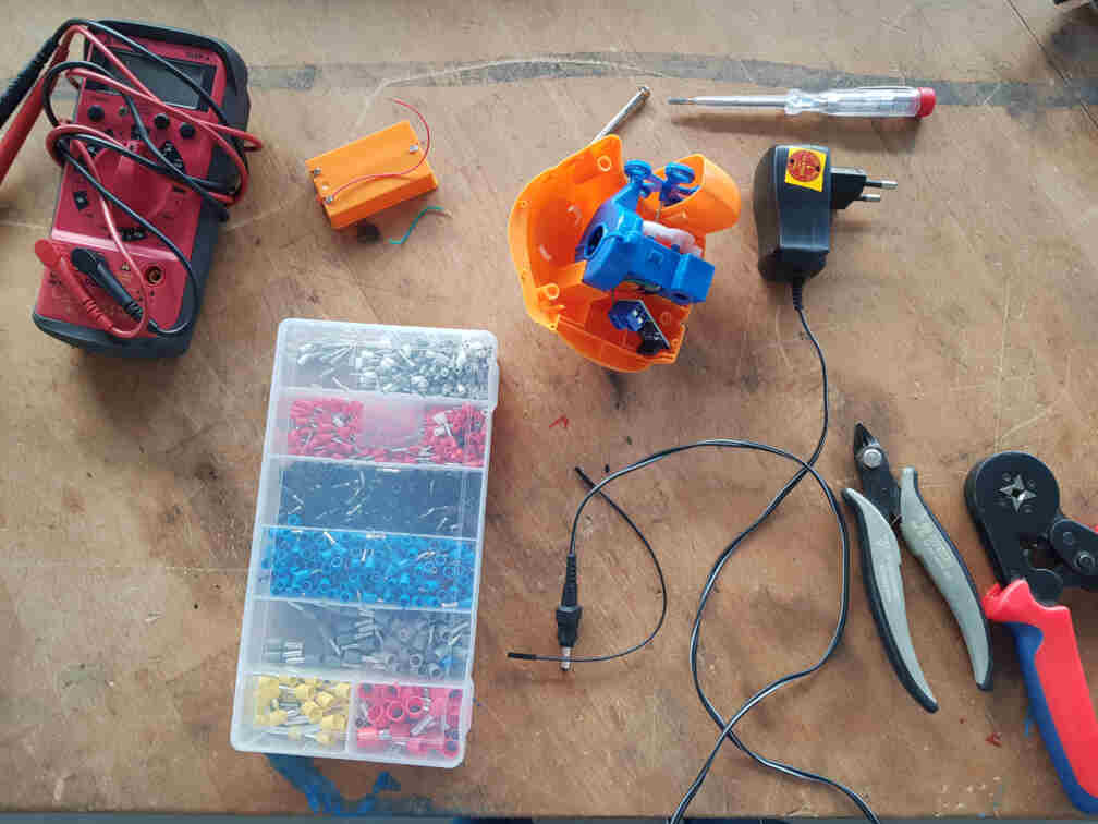
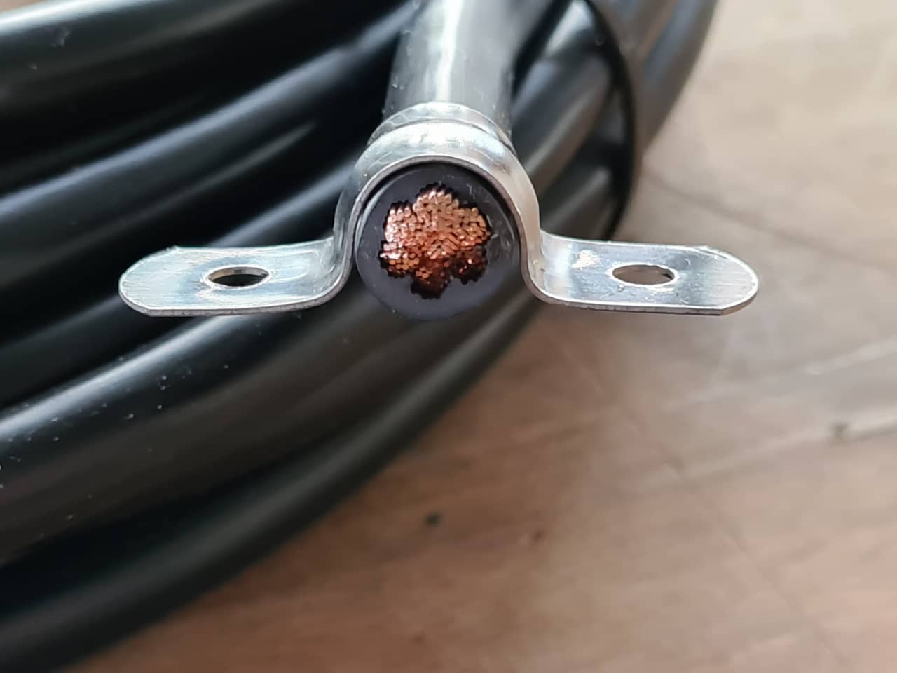
With me being out of the lab, I started procuring materials from at home - cables, cable terminals, crimping tools, linear actuators and the like.
These were the cables (25 mm²) and clamps originally planned for the welder…
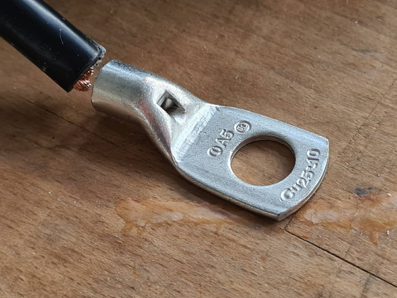
… and the cable would have used these brand cable terminals:
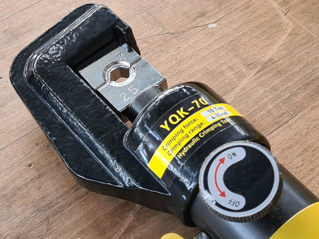
For crimping terminals, there was a hydraulic crimping tool available:
I also started thinking about the programming of the device. In the end, we wanted to have:
Linear Actuator Control
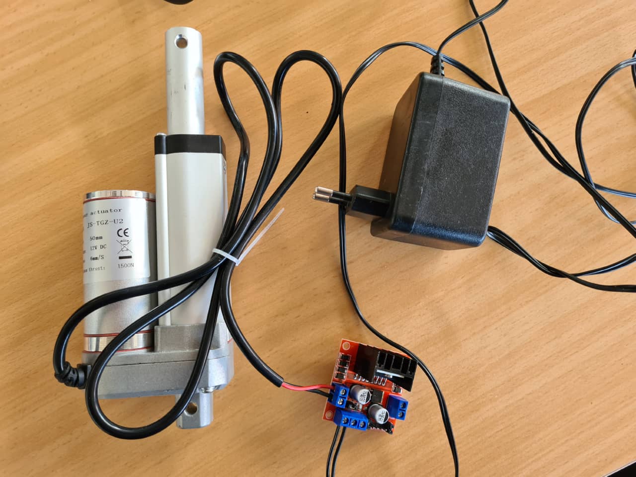
I started by testing and programming the motion of the linear actuator using a MotoDriver2 motor driver board, which uses an L298N motor driver IC.
This shows the Linear actuator used, the motor driver board and the 13V power supply:
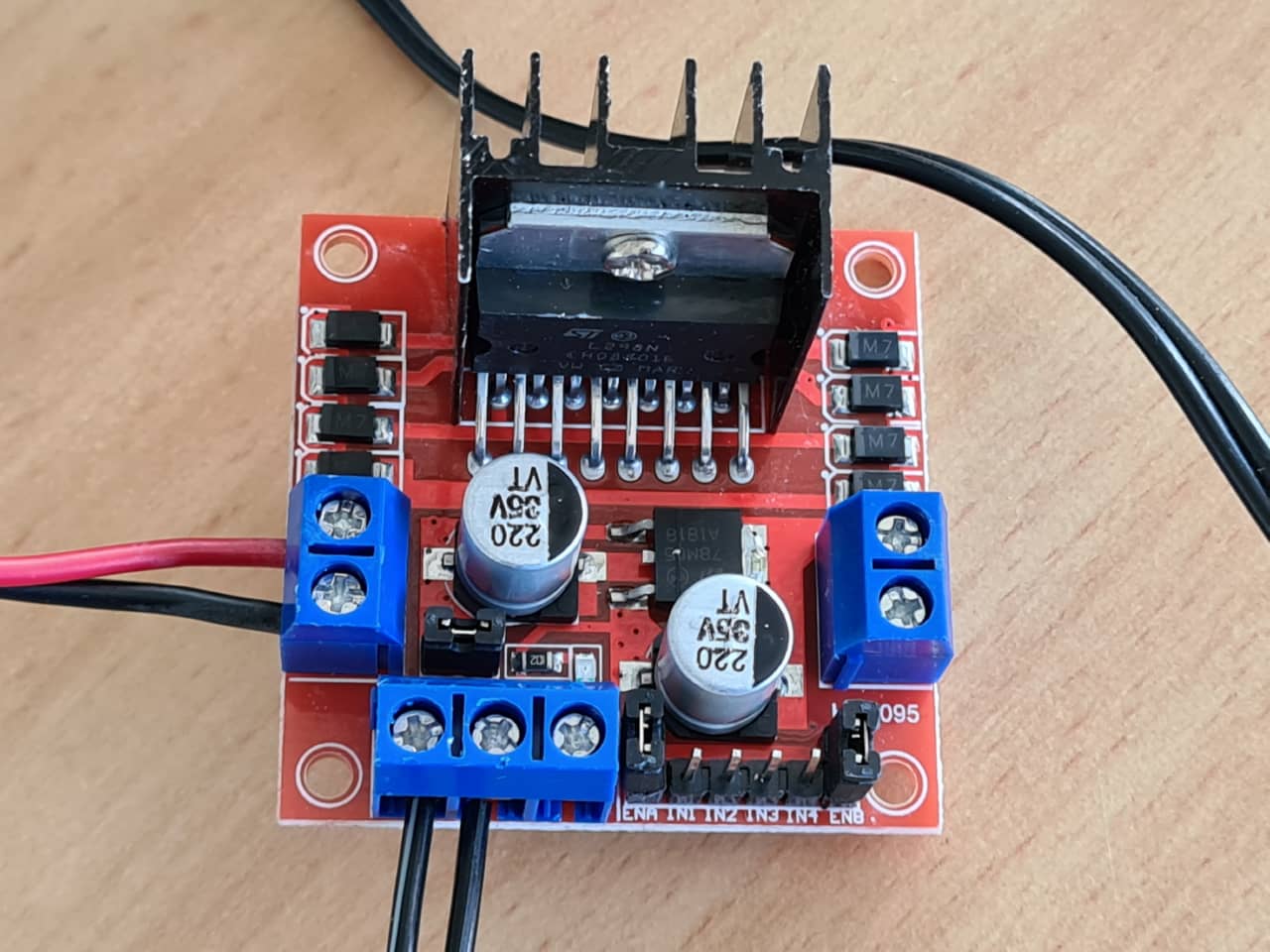
Here we can see the motor driver board. The red and black wires at the left connect to the motor, the bottom two wires are coming from the power supply. No logical connections to the Arduino have been made here, yet:
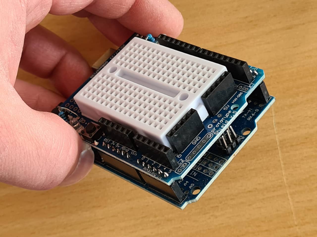
This is the Arduino UNO used for prototyping the setup. We used a prototype shield with a mini bread board on top to quickly make circuit changes on the fly:
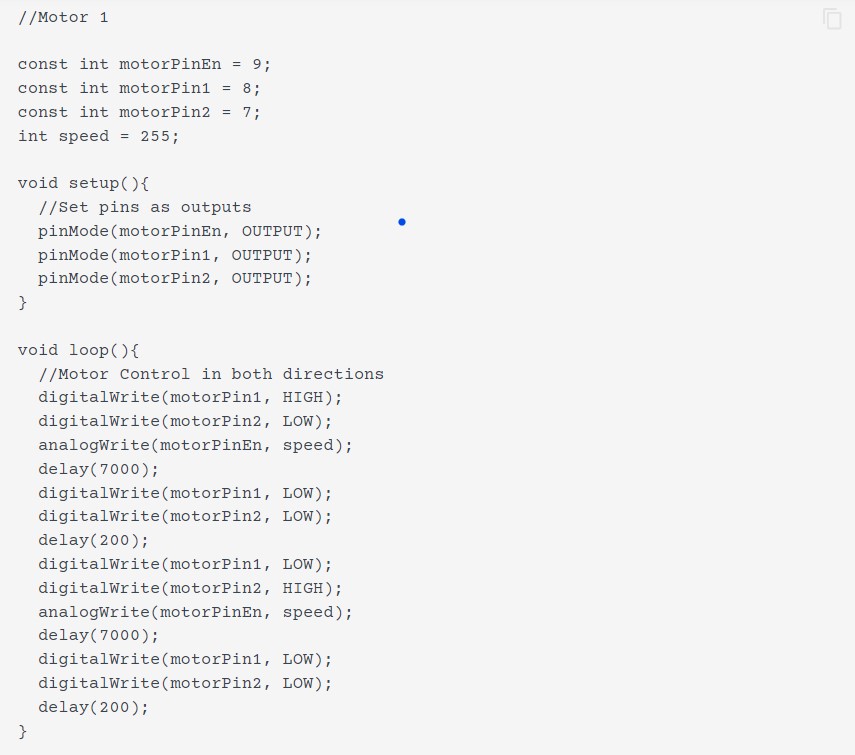
The example code from the manufacturers data sheet kind of contradicted other code examples I could find only that used the L298N motor driver IC also used on our motor driver board (I reduced the provided example to one motor only):
The example above would move the motor, but in the end I went for the more explicit code inspired by this L298N tutorial website , which showed following excellent schematic to illustrate the inner workings of the driver board:
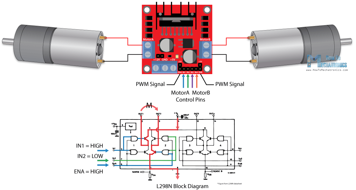
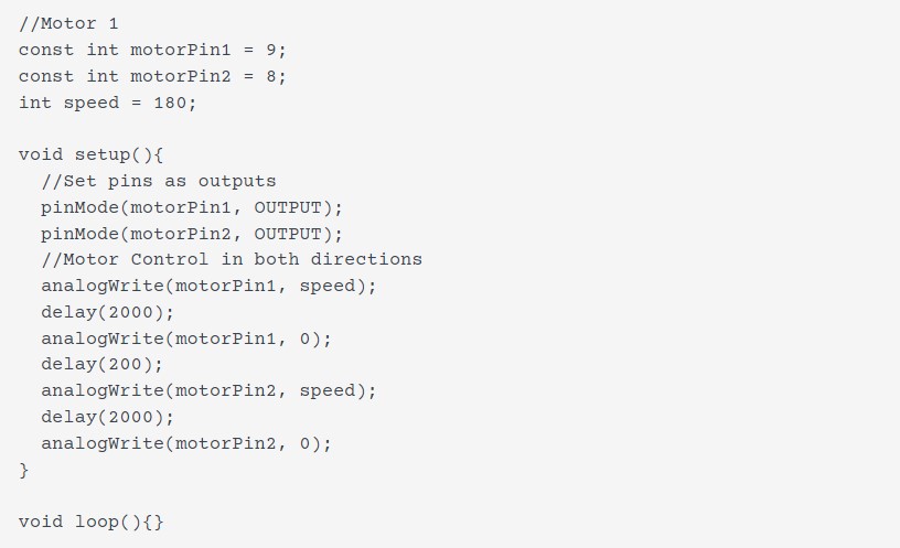
This is the MWE for the motor control using the Arduino:
This also used analogWrite (so sending a PWM signal) on the motor driver’s ENABLE pin to control the speed of the motor as intended - the way it was in the official datasheet was a bit more hacky.
In the beginning, the motor didn’t want to move at all, which led me to investigating other L298N code examples in the first place, but then it struck me I had made the simplest mistake - not connecting the Arduino’s and motor driver board’s GND connections. D’uh! Once both GNDs were connected using a jumper, the linear actuator happily extended and retracted.
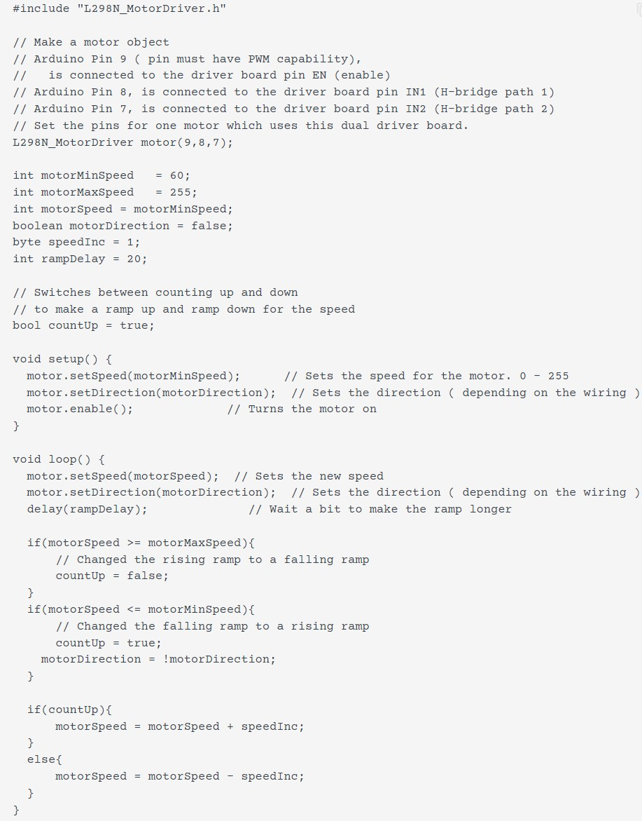
In the end, I already knew that quite a few more systems would be added to the Arduino later, so I immediately investigated more elegant ways to drive the motor without as many delay() function calls and blocking all the rest of execution. After looking into a number of L298N-centric code libraries, I settled with the L298N_MotorDriver, version 1.0.1 library by author Alex Krieg, which can be found using the Arduino IDE‘s library manager.
The resulting code was a bit cleaner than the code before, even though it still relied on using delay() function calls - yet much shorter ones, not blocking execution as much. I made the motor extend and retract periodically, accelerating and coming to a halt at the turning points. This was fancy enough for now:
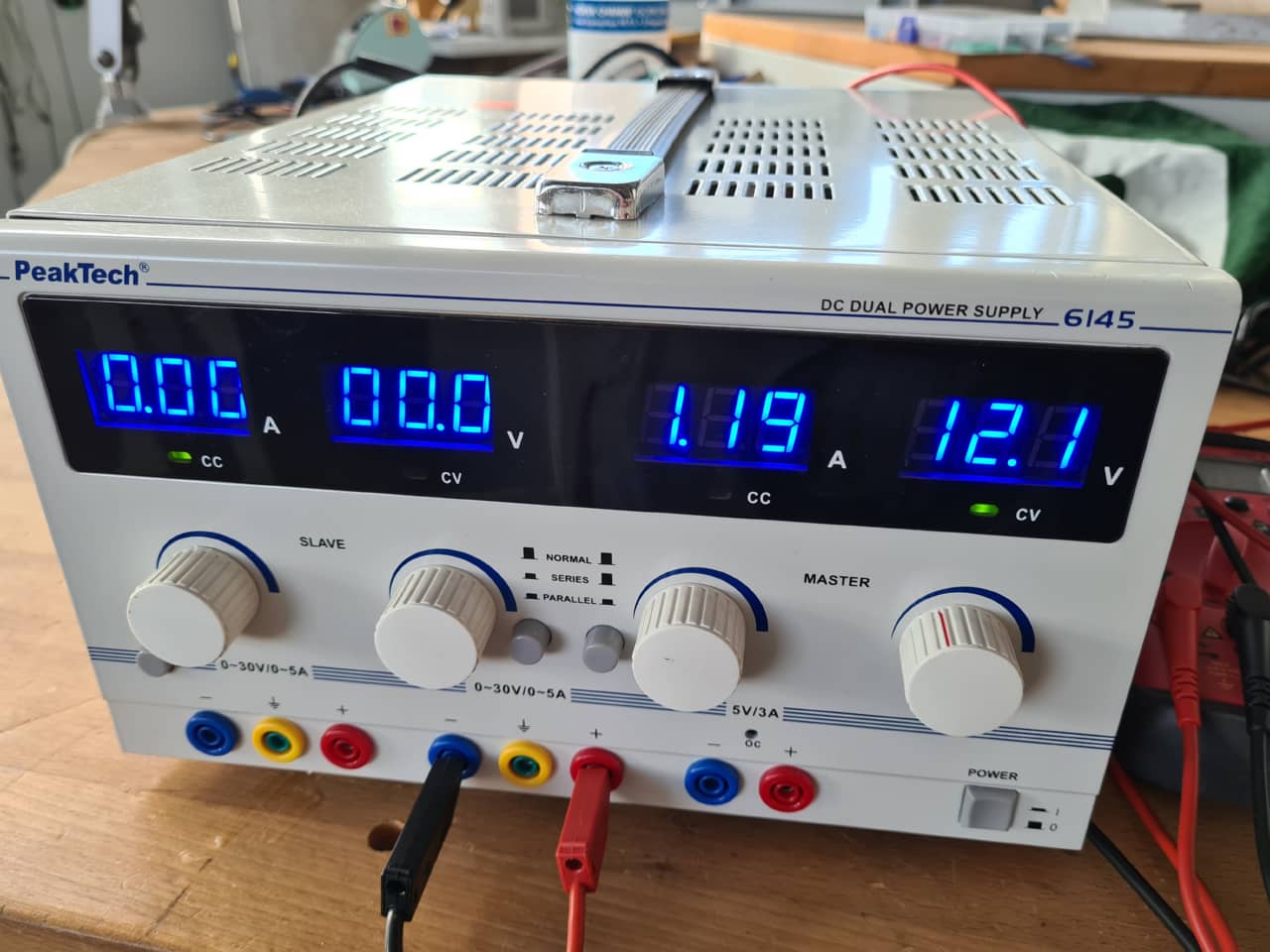
Here is the motor running at 12 V using a bench top power supply to test its extension current:
Huge Changes
Meanwhile (remember: I had been knocked out for a good while of machine design week already, this was around Easter in the final week already), a huge change had been happening to our original design. An individual the university hosting our FabLab raised questions about the electrical, fire and user safety of the homemade device. This raised our awareness about building and using machines like that in an openly accessible space like our FabLab, where there is a lot of general student traffic - and people don’t always stick to the rules of not using machines until initiated…
Long story short: We (painfully) accepted that building a device up to German electrical code to operate in the FabLab was not a thing to be done in the remaining days (and would have involved quite a few external parties, if allowed at all). While a painful lesson, it was also a good lesson. User and fire safety in a space like a FabLab should be paramount and not be taken lightly, just because a YouTube-video showed a similar device working. There's tons on YouTube videos that show devices I wouldn't touch with a stick, and while the one we picked as initial inspiration had looked pretty sound, execution in our place would have warranted a whole new level of investigation into the relevant safety aspects. Time to move on.
Building on what we had so far
Since starting out with a whole new machine design would not have been possible in the time left, we decided to turn the existing frame and jaw actuation mechanism into a nonsense-machine. The plan was to make a monster/crocodile art piece for kids out of it that could open and close its jaws automatically when someone was standing in front of it or actuating a sensor. Since kids love soap bubbles, it should also spew bubbles while doing so :)
Adding a Sensor - Ultrasonic Range Finder
We wanted to integrate a sensor into the device that would trigger when a user was close enough to the machine or waved her hand in close proximity. At the same time, we wanted to be able to set up the trigger distance in code, since we didn't know the exact, final layout yet. We decided to go for an ultrasonic range finder, which we have plenty of in the lab. The HC-SR04 we used has a fitting Arduino library that comes with following MWE (change ot fit the pins used on our Arduino):
This code measures the distance from the sensor and returns it via Serial console. If the measured distance is unknown (e.g. when the sensor is too far away from anything to measure) it returns -1.0. The sensor has a measuring range of 2 cm to about 300 cm, so any distance above approximately 3 m will return a -1.0.
Merging Code
The Ultrasonic range finder code was then merged with the motor control code, so that the device would be inactive when no sensor input was seen. Once a certain trigger distance (in our case for testing: 30 cm) on the sensor was hit, the motor would trigger and the device would move its jaws. After one full cycle of the jaws, the device would stop again and wait for input (or continue moving if the sensor was still triggered):
In the setup() function of the Arduino, I also added a timed, 9 second stroke of the motor to fully retrieve it. The motor does have end switches at both ends of the stroke, but no other kind of feedback, so to always start the device in a known configuration, it retrieves the piston until it hits the limit switch whenever powered up. THis was necessary, as in the whole communications kerfuffle over Covid isolation and Easter, we had received a wrong linear actuator, which externally looked the same as the one we intended to buy originally, but had a larger housing and larger dimensions overall. Thus, when the mechanism was built - and even after Aaron made modifications to the jaw to set the hinge pin for the piston higher - the piston was not safe to fully extend or it would risk breaking the jaw. The fixed starting position helped making it move safely. I also tuned the stroke length of the piston such as not extending all the way to the other limit switch of the piston, but so that it stopped and reverted motion in between the end points.
Adding a limit switch
There was one painful moment where the actuator actually extended too far, closing the jaws completely and breaking the hinge drilled into the multiplex - pushing a maximum of 1500 N, the motor did not seem to have any problem doing so… So in the end, we decided to also include a limit switch to allow us to quickly cancel the stroke (while testing) and to set a safe, physical limit when on the machine.
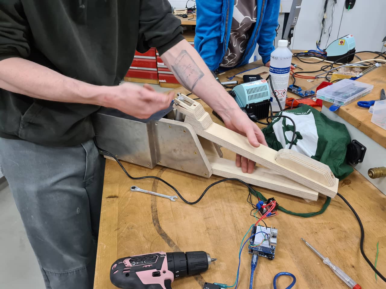
This is the device after a mishap with the mismatched actuator. The jaws closed too much, forcing the hinge and breaking it (this was fixed later by Aaron):
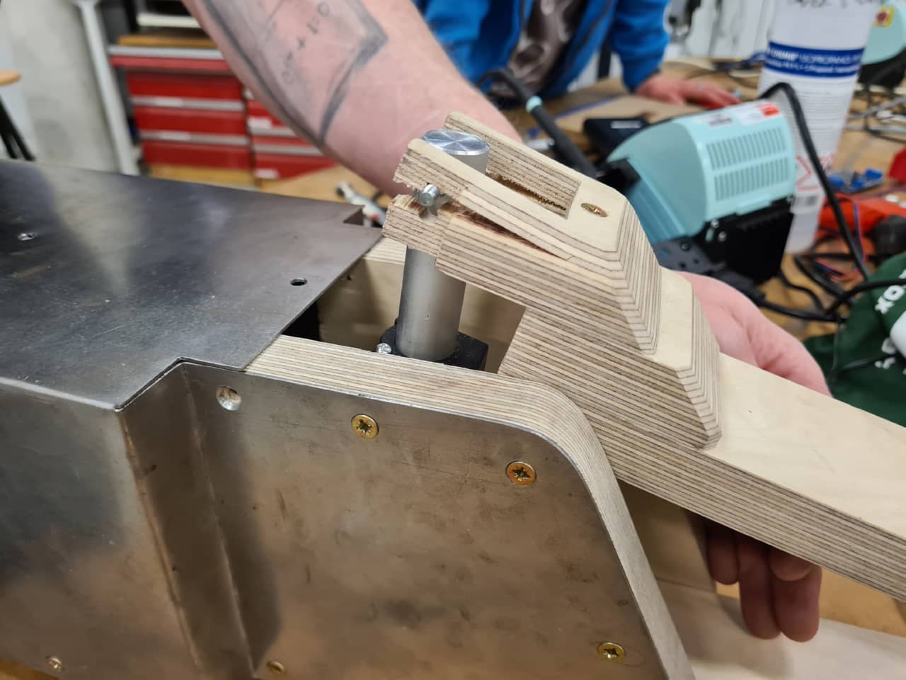
Close-up of the broken hinge:
The piston would simply retract to a safe starting position (such as when powered up) when hitting the limit switch. Adding the limit switch led to following code:
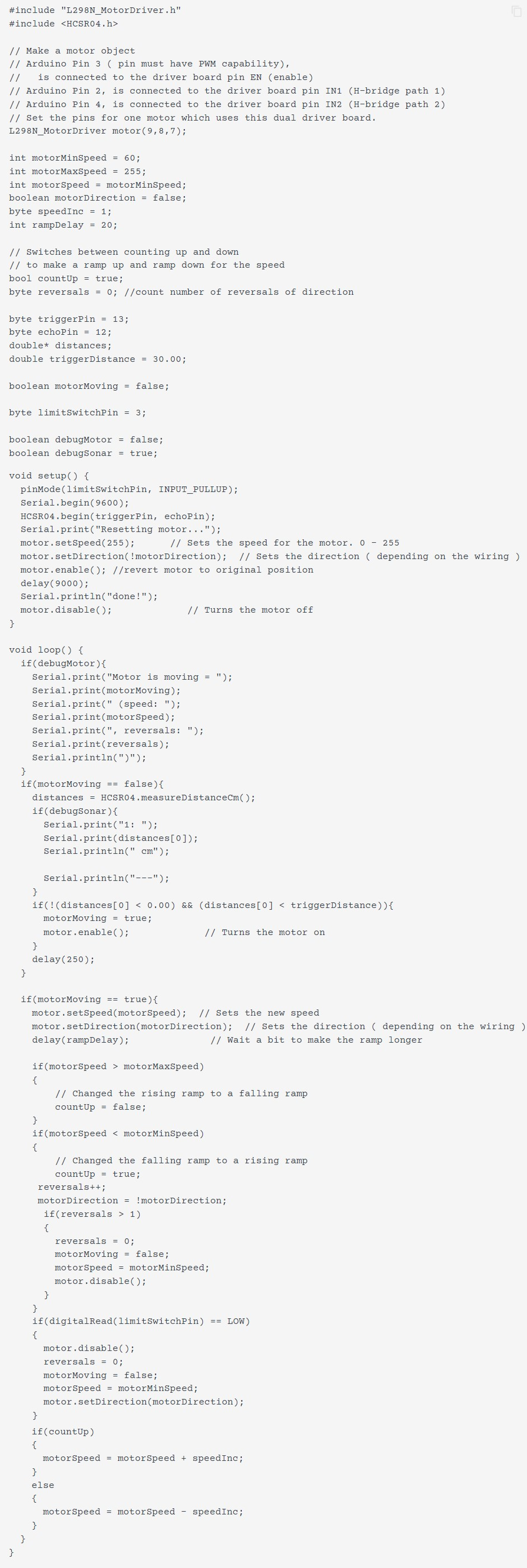
This used a micro switch connected to a pin using the ATMega's internal pull-up resistor, grounding the pin when it was triggered. When triggered, the same routine as when powering up was executed (retracting the piston fully), then operation would continue by waiting for sensor input.
Adding a Radio
The bubble machine that was originally intended to distract from looking at the welder when active was a totally separate subsystem developed by Leen. Since the bubbles would have been to distract from the Welder, the bubble machine would have had to be placed somewhat away from it. Hence, radio communication using an NRF24 radio should be used to communicate between the bubble machine and the welding machine. More on that can be found in Leen's documentation. We tried merging the radio function into the main machine’s Arduino code, but using the RF24 library, version 1.4.2 by author TMRh20, we couldn't get communication working at all, while it did work fine when using another pair of Arduino Nanos for radio communication.
We suspected there might have been some hidden resource conflict between the libraries already used (Range Finder, Motor Driver and Radio libraries), preventing the radio to work from the main Arduino. I've had similar things happen using certain tone generation libraries that would then claim certain timers for generating waveforms and blocking said timers from being used by other libraries trying to access. In the end, we decided to keep the existing pair of Arduino Nanos with their attached NRF24 radios and simply trigger the sending Arduino using a pin-to-pin connection on the main machine's Arduino. Here's the code with the triggering pin for the bubble machine. Code for the sender and receiver Arduino Nanos can be found in Leen's documentation:
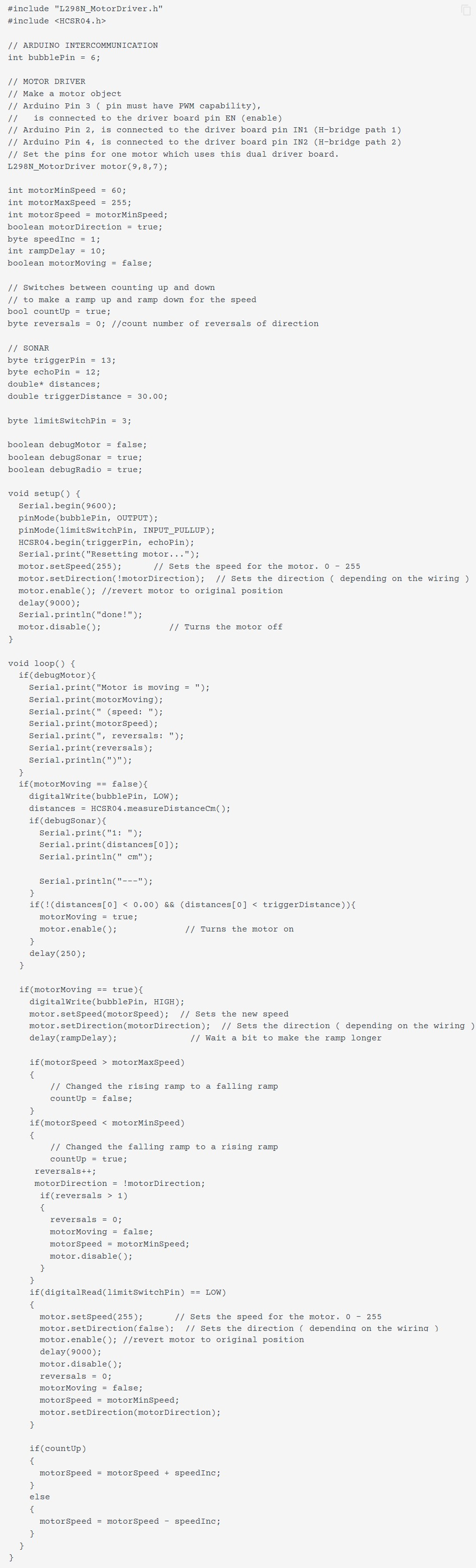
This was the final code used for the presentation of the device, with range finder, motor controller, inter-Arduino communication and limit switch integrated.
Lessons Learnt and Future Lookout
We did learn that safety should always be one of the deciding factors in our future designs. Machines in our FabLab are relatively accessible to a certain public, as we have lots of student traffic. We also learnt that we have to communicate tighter as a team, especially when unexpected stumbling blocks (sick team members, sick children, order problems…) are put in our way.
Maybe, in the future, we might find other creative uses for a machine of such frame. Slow-Mo back-patting device? Industrial size tea-steeping machine? Coconut Piercer? We'll see…