Computer-Controlled Machining
Hero Shots
Click Here for Our Group Assignment
Something Big
File Downloads From This Week
- CAM for Group Project
- CAD Assembly
- Backplate CAD
- Top and Bottom of Outer Frame CAD
- Sides of Outer Frame CAD
- Top and Bottom of Small Frames CAD
- Sides of Small Frames
- CAM for Outer Frame Parts
- CAM for Faces of Small Frame Parts
- CAM for Back of the Top and Bottom of the Small Frames
- CAM for Backs of the Sides of the Small Frames
- CAM for Backplate
Initial Reaction
The topic for this week is large format machining, particularly numerically controlled machining. The individual assignment is to "make something big." The idea is to make an assembled object from a single sheet of plywood with at least one dimension greater than or equal to a meter long. Although I am new to controlling the processes with the computer, I DO have some knowledge of woodworking and joining. My initial reaction from the lecture this week is to be dubious. We were shown a series of Japanese wood joints that are simply not possible or are prohibitively impractical to create using CNC machining, and certainly not using 2D profile cutting, which is the focus of the topic for this week. I have a feeling that the masters of this craft still do these things by hand, because it is the best way, with the least amount of waste...at least outside of mass production. Extra credit is available for creating assembly that holds together without glue or screws, but I am not looking for the extra credit this week. My aesthetic would suffer from the introduction of visible dog-bones and, since this project will be the frame and structure for my final project, the aesthetic is important to me. I will use overlapping and locking joints with hidden dogbones wherever they are necessary, but I intend to glue the parts of the assembly that will not need to come apart again.
After Local Workshop
In the local workshop this week, we had a crash course in CAM production using Fusion 360. Ahmed walked us through the processes of creating contour cuts, pockets, holes and cutting the outline of parts, as well as how to set-up the tool parameters and how to create tool libraries that can be used again later. Then we spent a significant amount of time discussing safety protocols and how to safely, and effectively, adjust cutting parameters like spindle speed, feed rate and cutting depth. I am comfortable with all of these terms and parameters and the safety precautions are common sense to me, but I have never made a CAM before and I am not very good at Fusion yet, so I have my work cut out for me.
Setting Up the CNC Machine
Pre-Work
Before
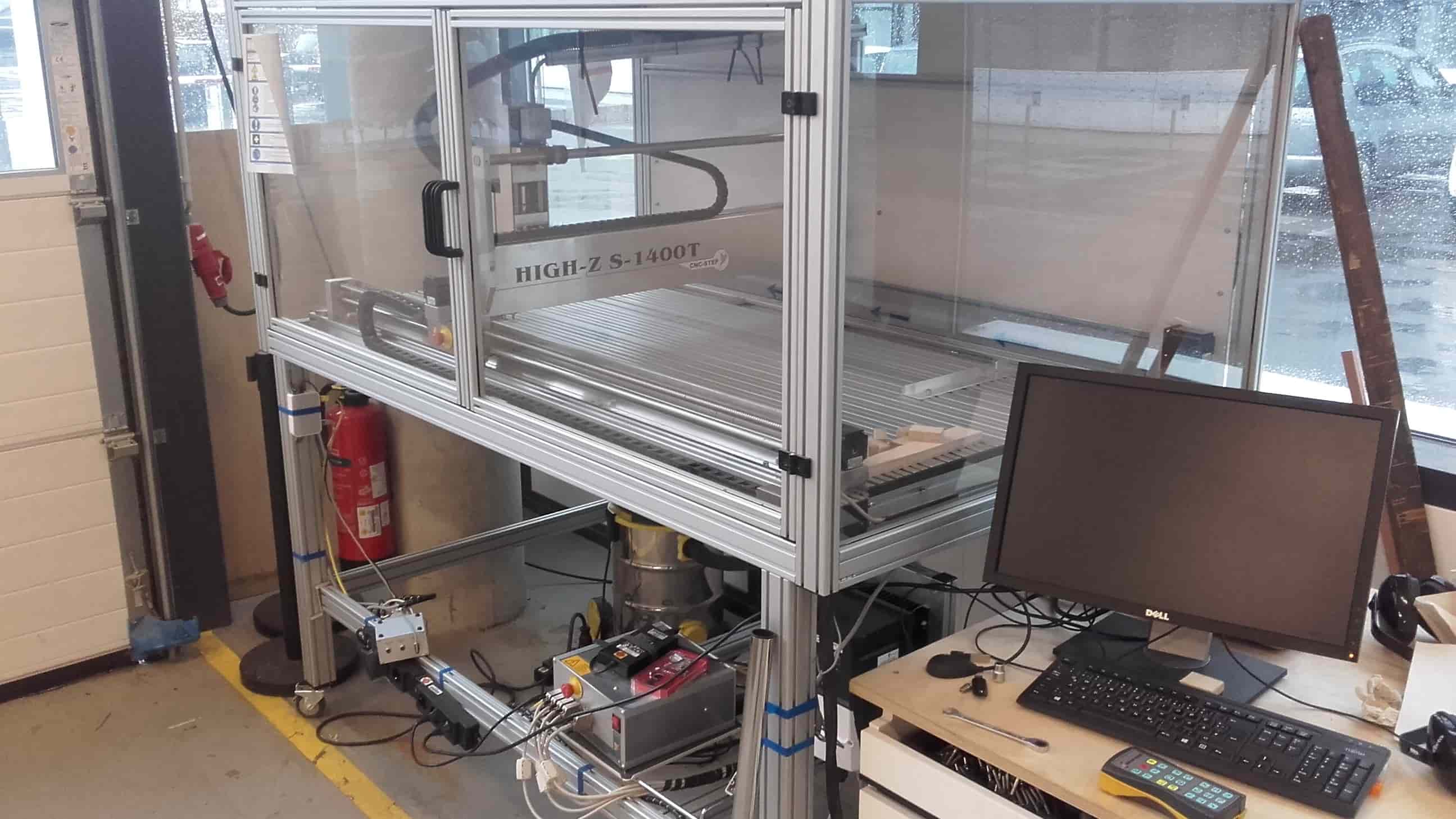
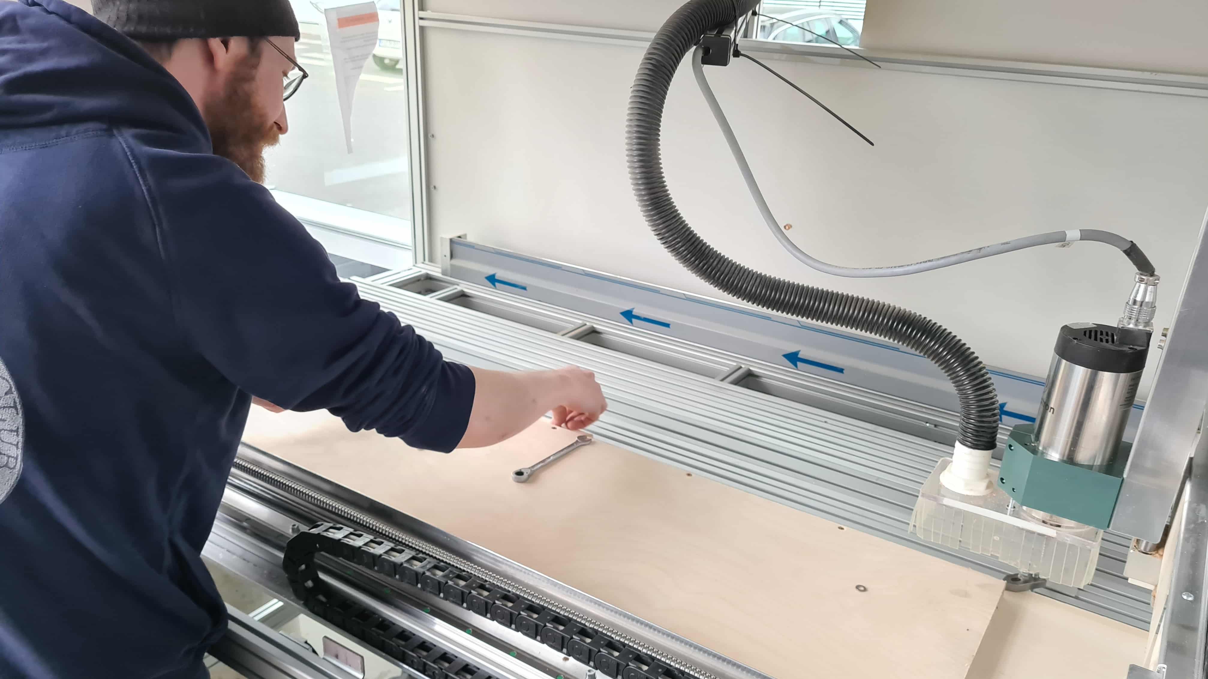
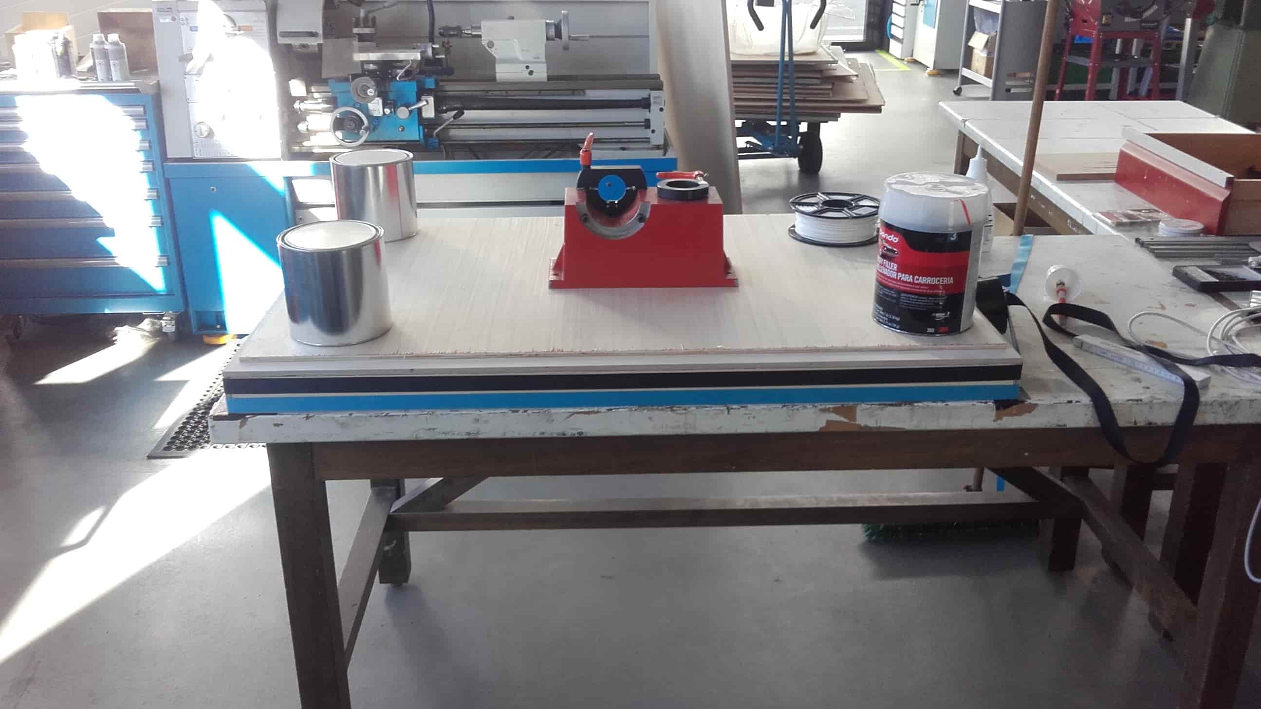
In our lab, we have a CNC-Step High-Z S-1400T large-ish format CNC machine. It hasn't gotten much use yet, and it hasn't been used at all since we reorganized and rearranged the lab at the end of last year. So we had some work to do just to get it cleaned up and battle-ready.
After
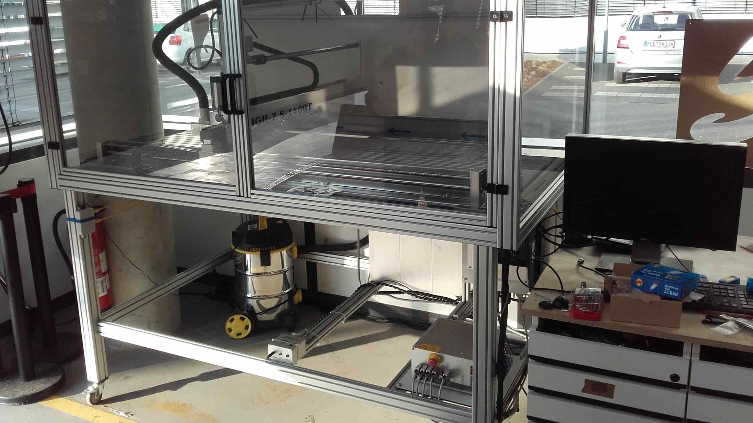
I rerouted and re-managed all of the cables beneath the machine; Roland cleaned out the bed and the computer area; and Leen got to work making the test piece for our group assignment. After a couple hours, the CNC machine was looking great and was ready for cutting...unfortunately, we weren't quite as ready...
Test Part for the Group Assignment
Creating the CAM
Getting Started
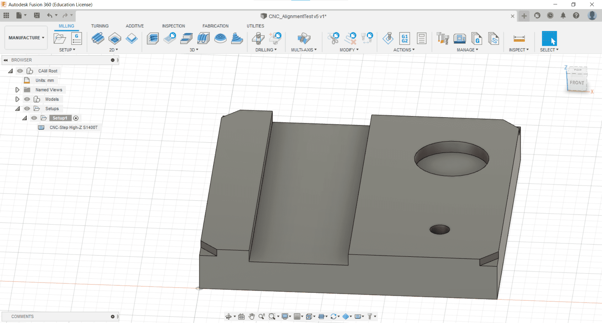
After importing the post processing, and machine libraries, and adding a couple of our tools to the tool library in the Manage tab of the Manufacture toolbar, I was ready to begin the CAM. I started by importing the test part that Leen had made the day before.
New Setup
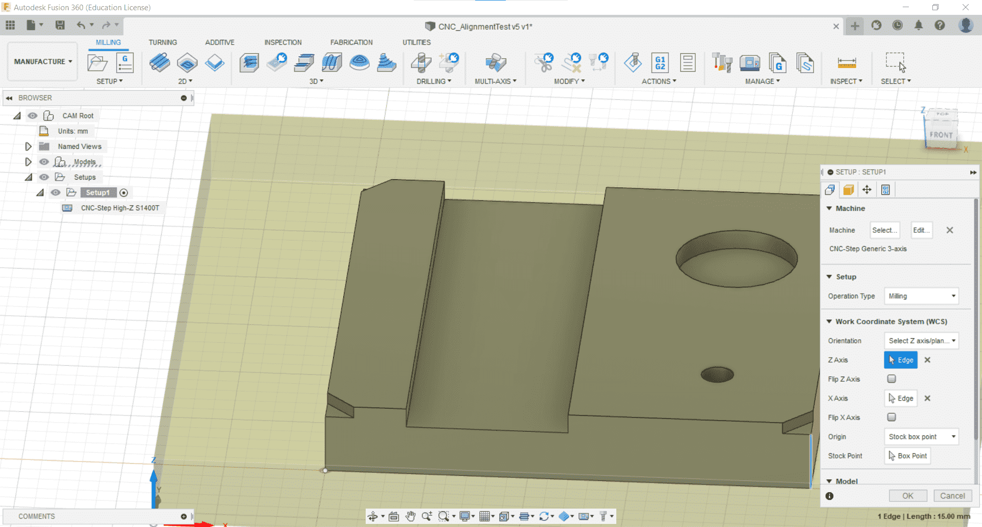
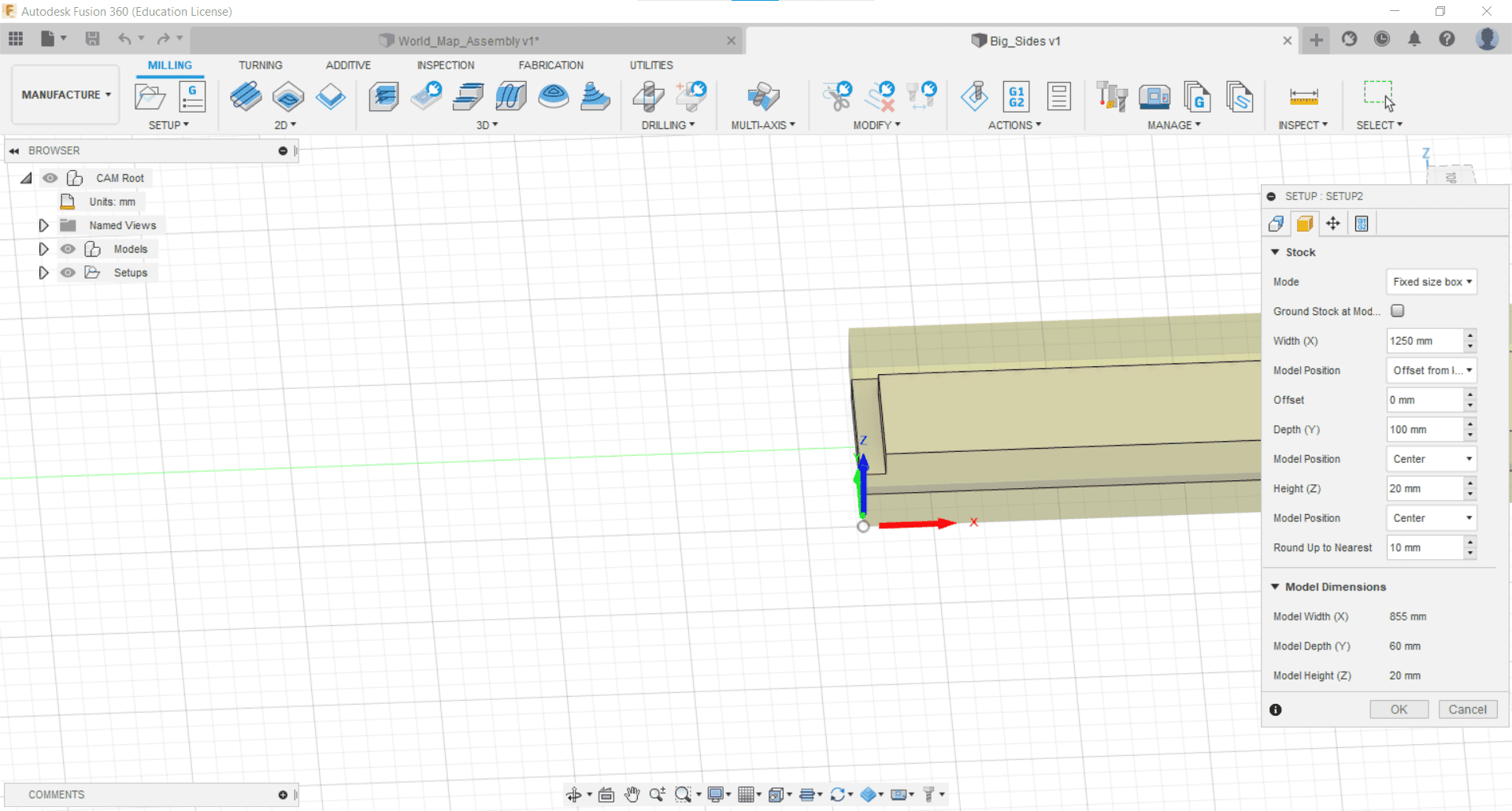
I created a new setup for milling and I placed the origin on the lower left corner and the bottom of the stock.
Stock
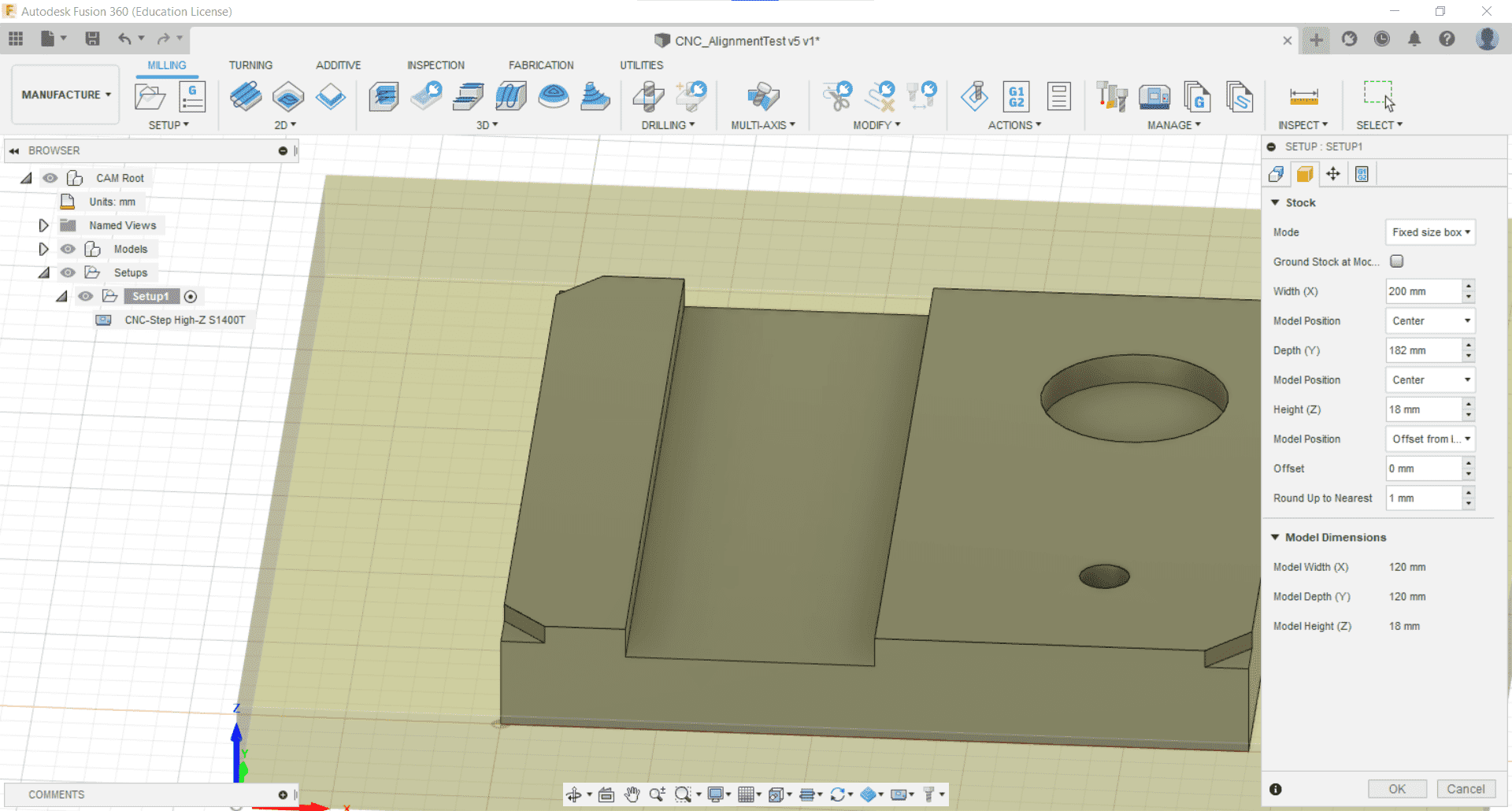
We had some scrap wood in the lab that would be suitable both for the workpiece and for the sacrificial layer beneath so I set the dimensions of the stock accordingly and aligned the part to the center.
Fixtures
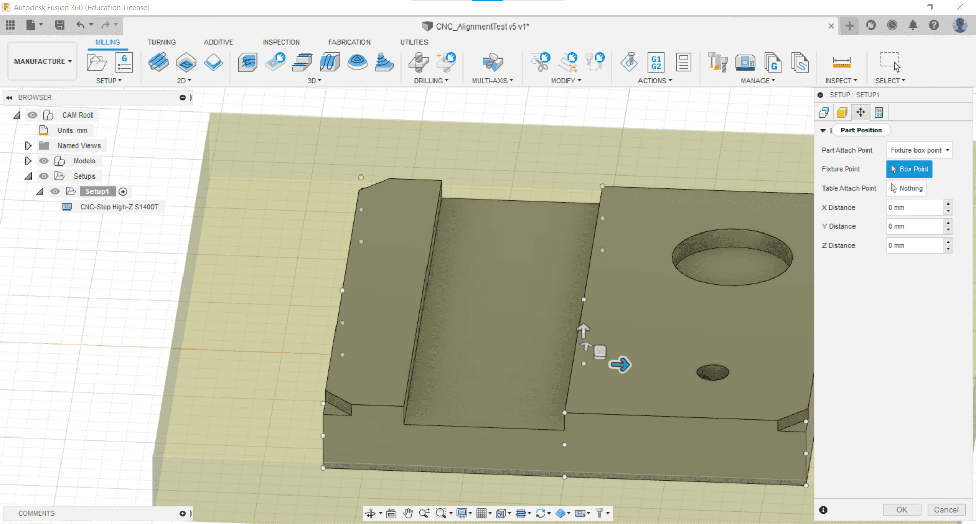
I decided not to model the fixtures and to just screw down the workpiece where I knew there would be no cutting.
Processing Setup

I also kept the post processing tab at its default values.
Bore
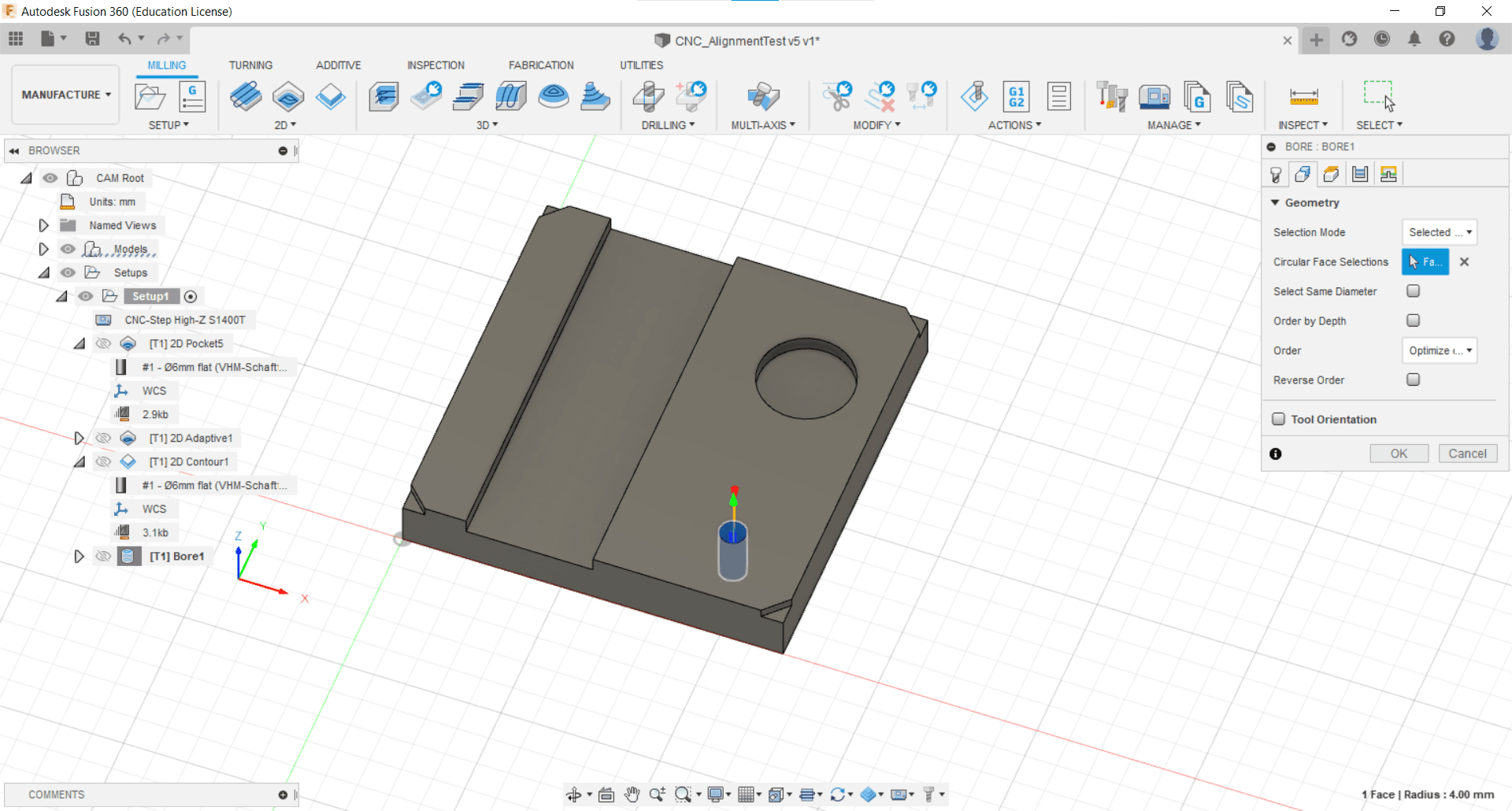
To mill the hole, I used the Bore tool in the 2D Milling tab. I selected the bottom of the hole.
Retraction Height
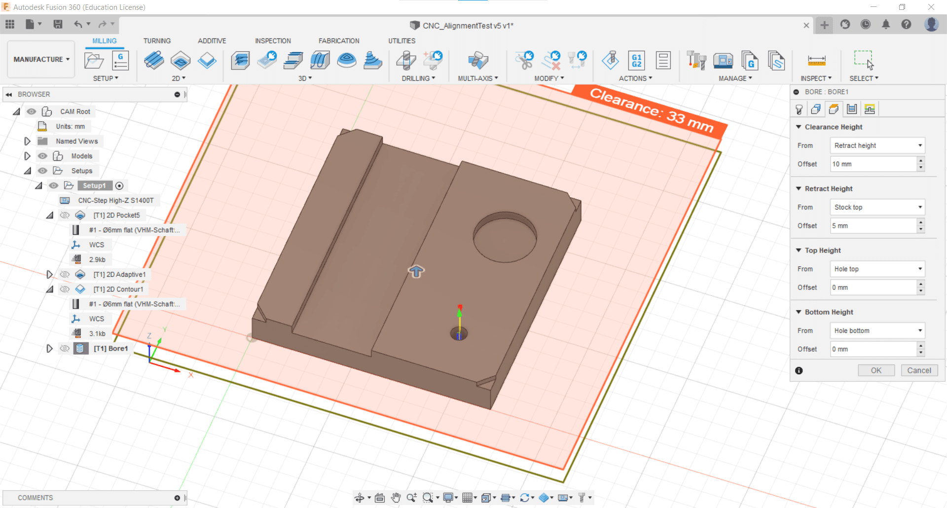
I kept the retraction heights at their default values.
Stock to Leave
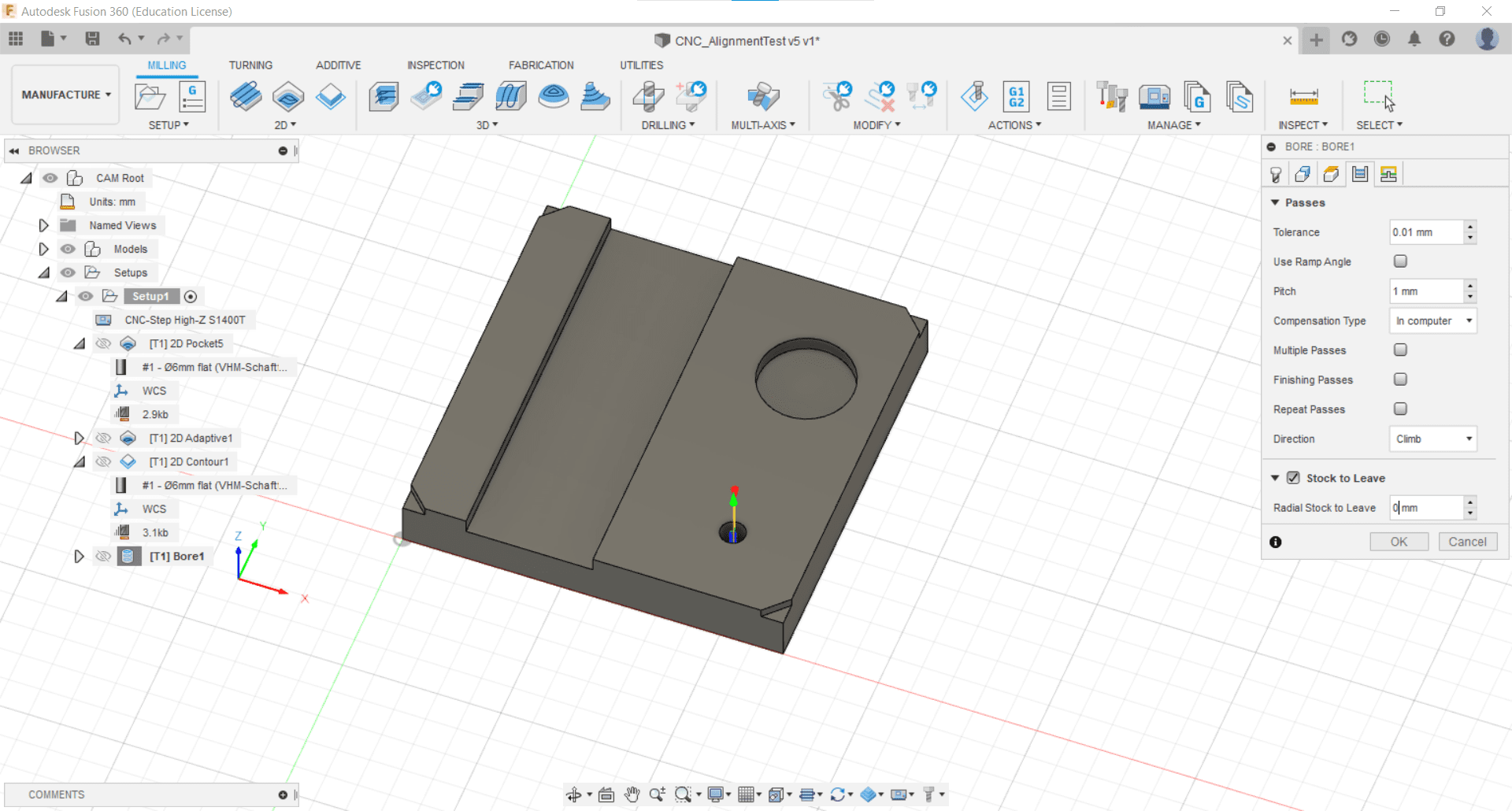
Since I didn't use multiple passes or finishing passes, I chose not to leave any stock in the radial or axial directions.
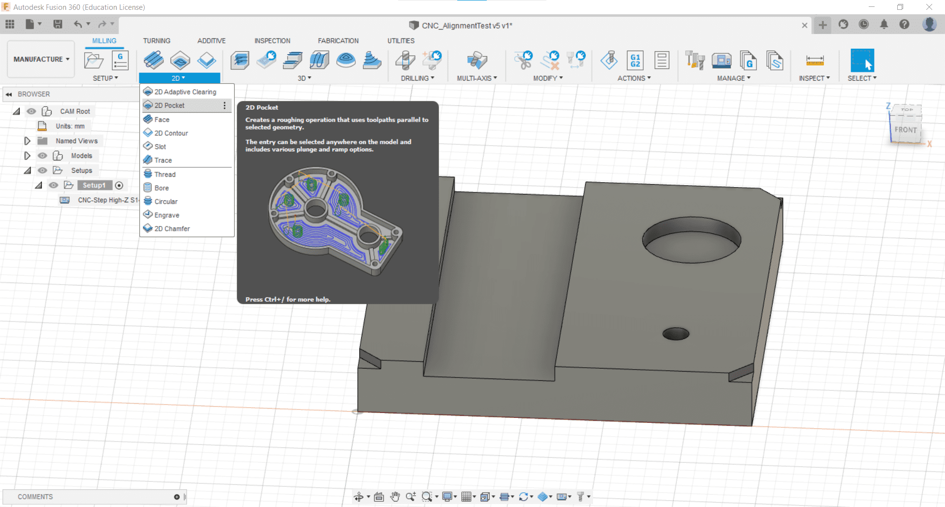
For the pocket, I decided to use the Pocket tool.
Tool
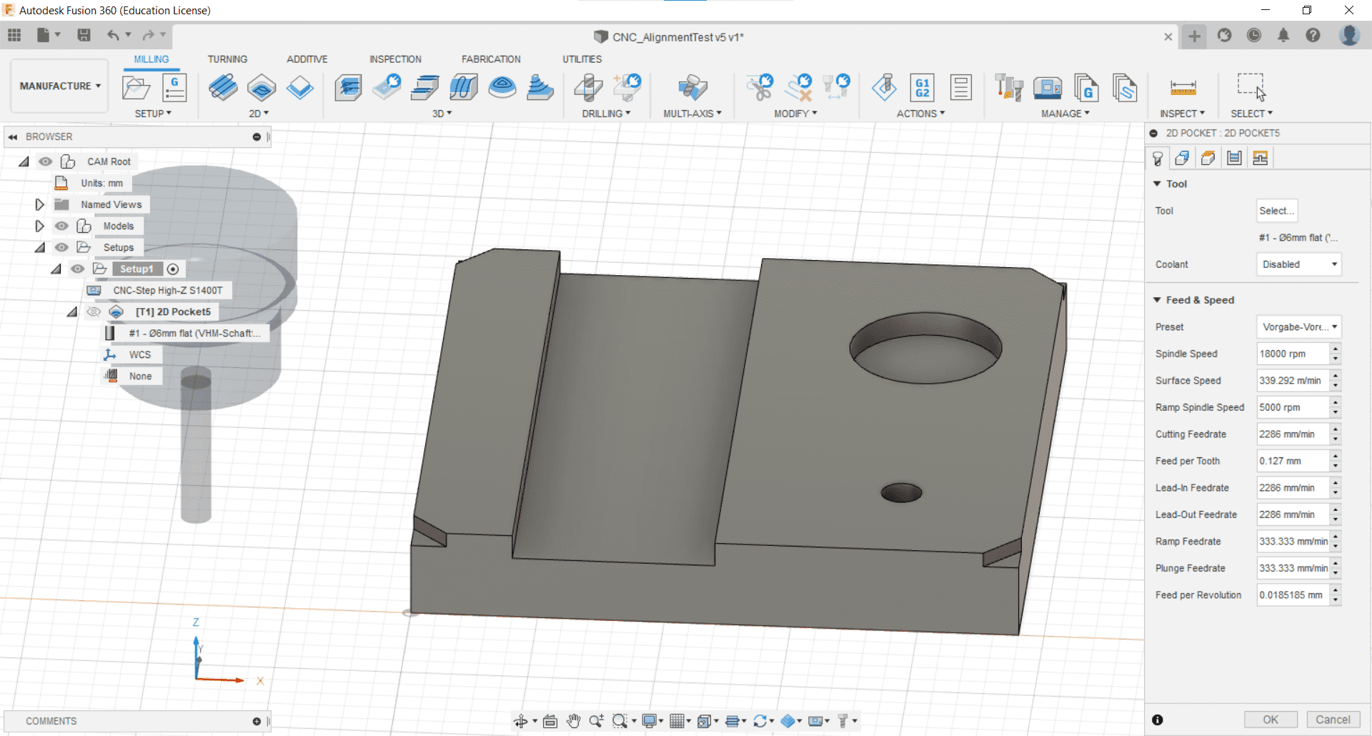
I selected the cutting tool to use,
Geometry
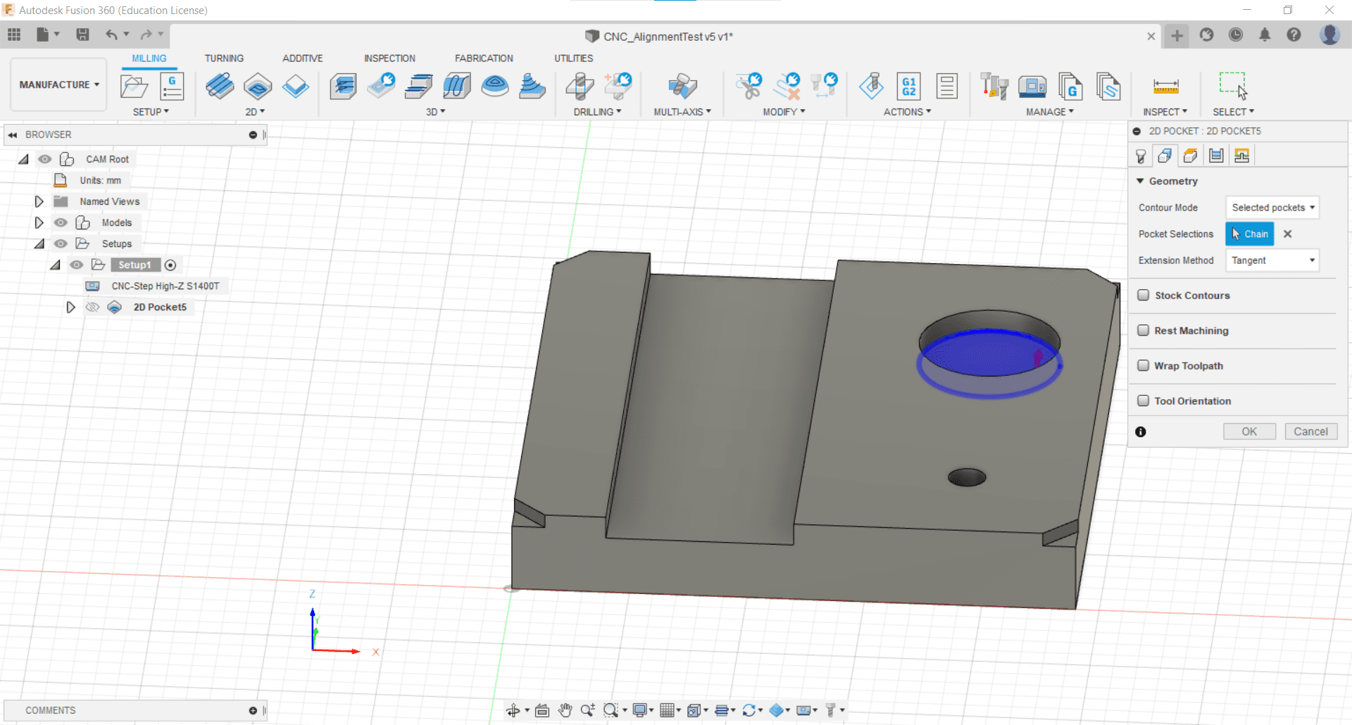
the geometry of the pocket to be cut,
Retraction Height
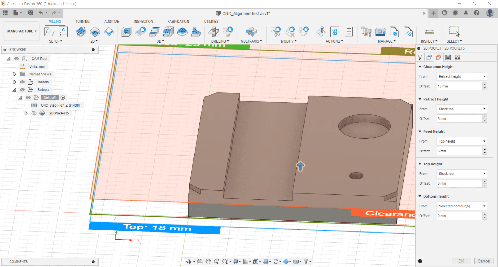
and once again kept the Retraction Height parameters all set to their default values.
Stock to Leave
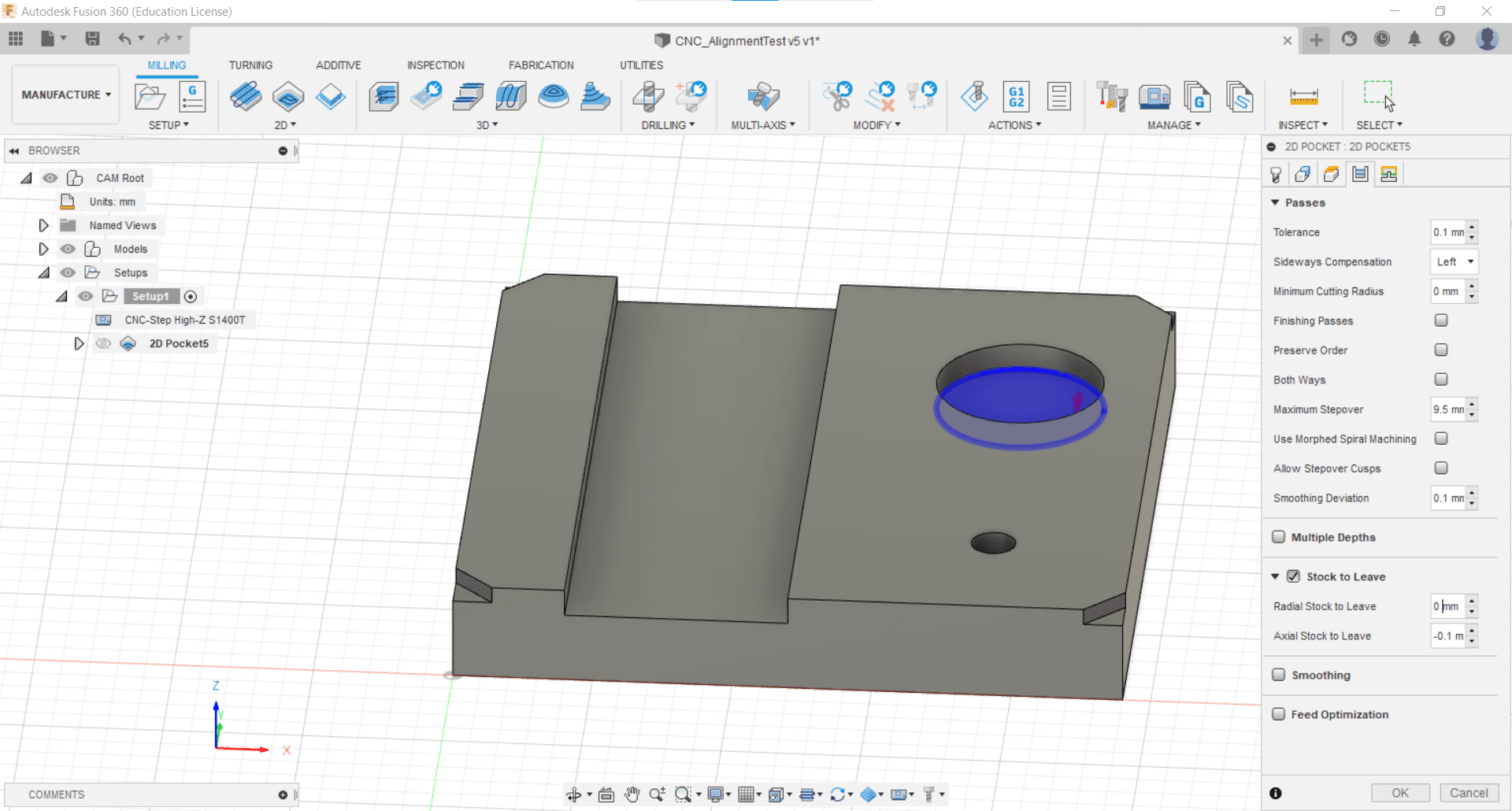
Since this was a test piece, I decided not to use multiple passes once again. The idea being, that we would see what the default parameters look like and then make adjustments from there. Since there were no finishing passes, I chose not to leave any stock.
Linking
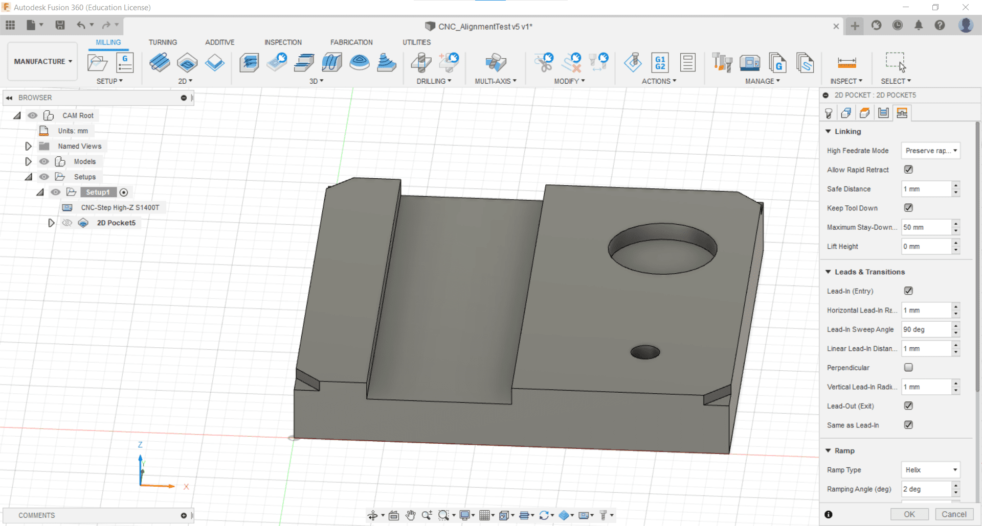
I also did not change any of the linking parameters.
Adaptive Clear
For the other features, I decided to use the Adaptive Clearing operation. I think I could have done these with the pocket operation as well, but I wanted to see the difference.
Parameters
I kept the parameters at their defaults once more.
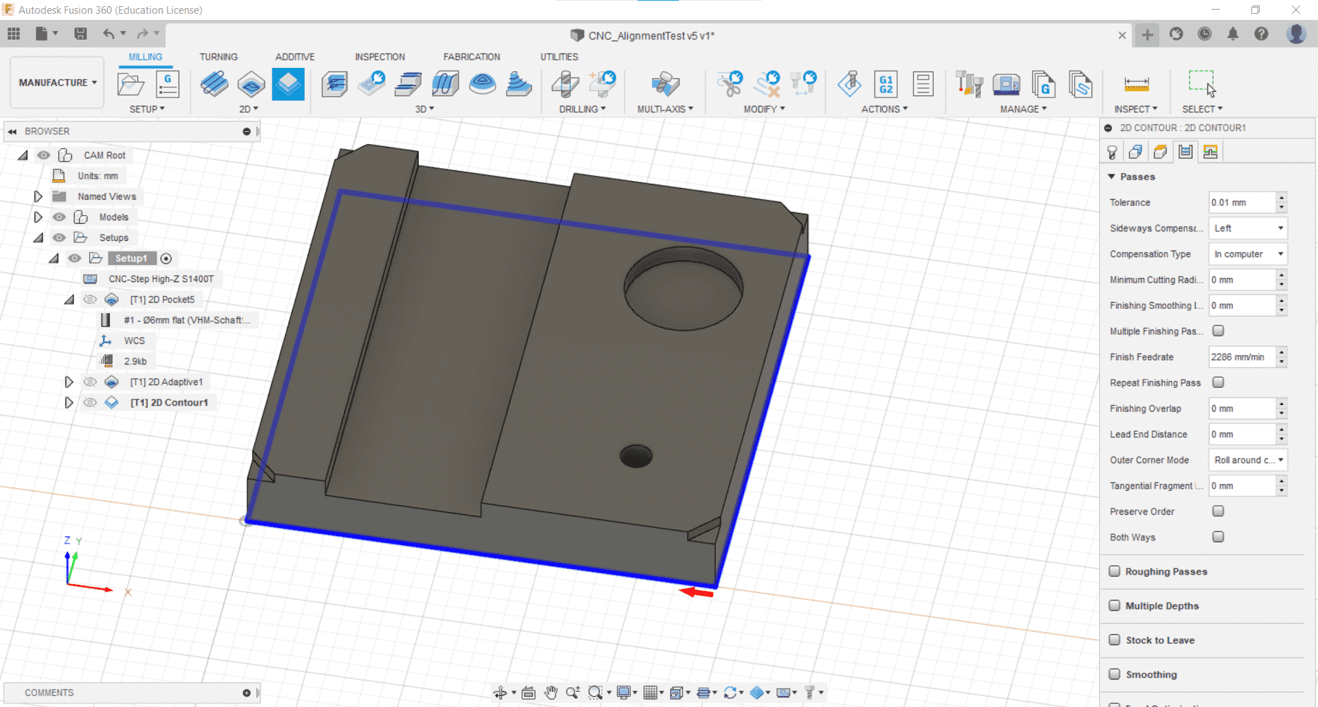
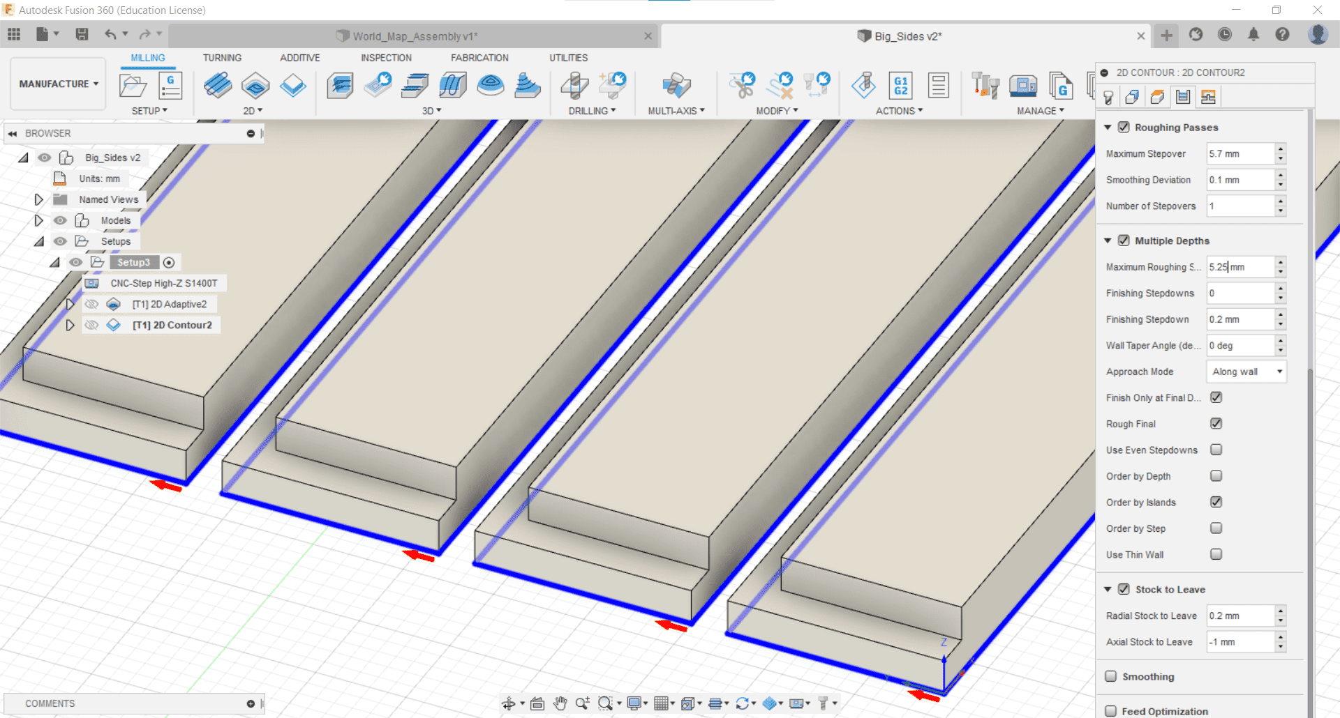
2D Contour
Finally, it was time to deal with the cutout so I selected the Contour Cut tool from the 2D Milling tab.
Tools and Geometry
And then selected the contour I wanted to cut after choosing my cutting tool yet again.
Multiple Passes
I kept most of the parameters at their defaults, but this time I used multiple passes so I changed the roughing stepdown depth to 5.1 mm.
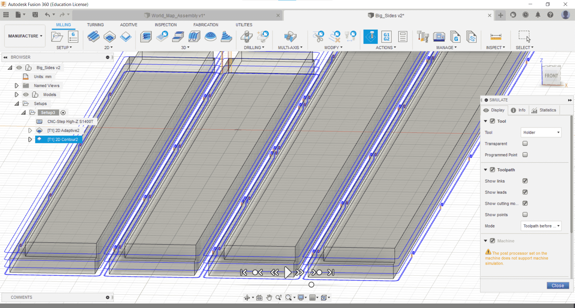
Simulate
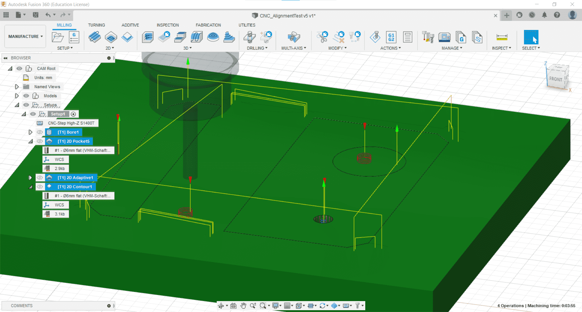
Then, in the Actions tab, I used the Simulate tool to visualize the tool-paths and make sure that everything was doing what I expected it to.
Tabs
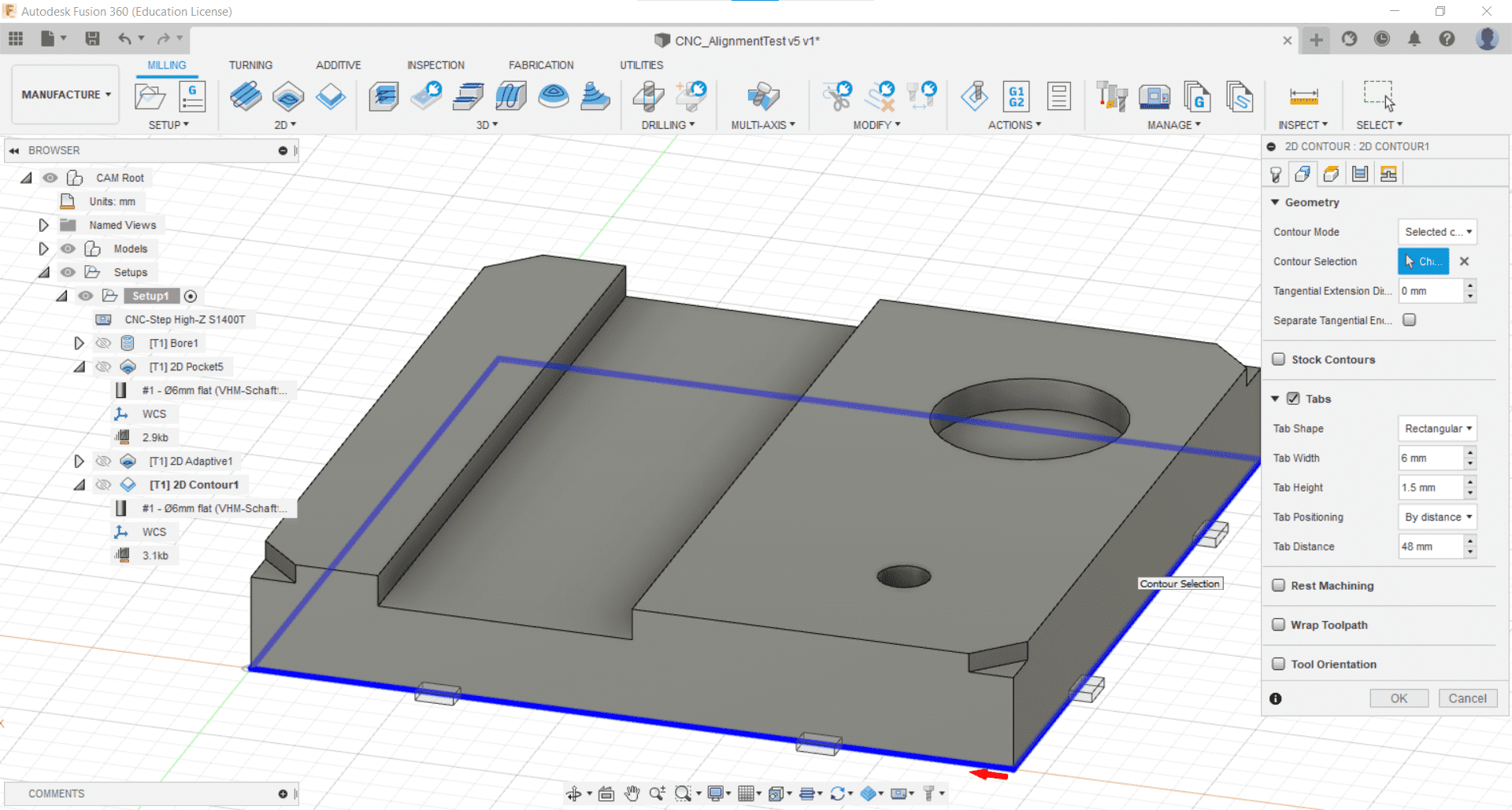
After watching the simulation, I realized that I forgot to add tabs for the cutout, so I went back into the operation by double clicking it and added them. I clicked the box and kept the default parameters.
Post-Process
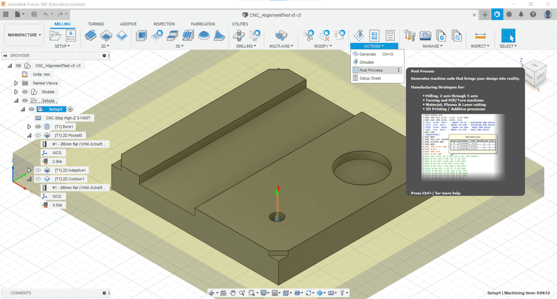
When the CAM was complete, I used the Post Process tool from the Action tab to generate the g-code for the CNC machine.
Checking the G-code
Warnings and Good Advice
I was warned by the director of my lab that, for some unknown reason, the post processing from Fusion 360 for our machine always adds a few reckless lines of g-code at the beginning and end of the CAM, such as what he referred to as a "homing dance." He advised me to learn what this handful of commands do, figure out why they are there, remove them if necessary or useful, and to simulate the entire g-code file, rather than just the pre-processed operations in Fusion. He also advised me to remove the tool after I setup the job and to run the CAM once just cutting air so I could make sure that there were no surprises when it came time to do the actual cutting. I was alone in the lab the day I was cutting so these warnings made me paranoid and I spent a lot of time checking and double checking the CAM and setup.
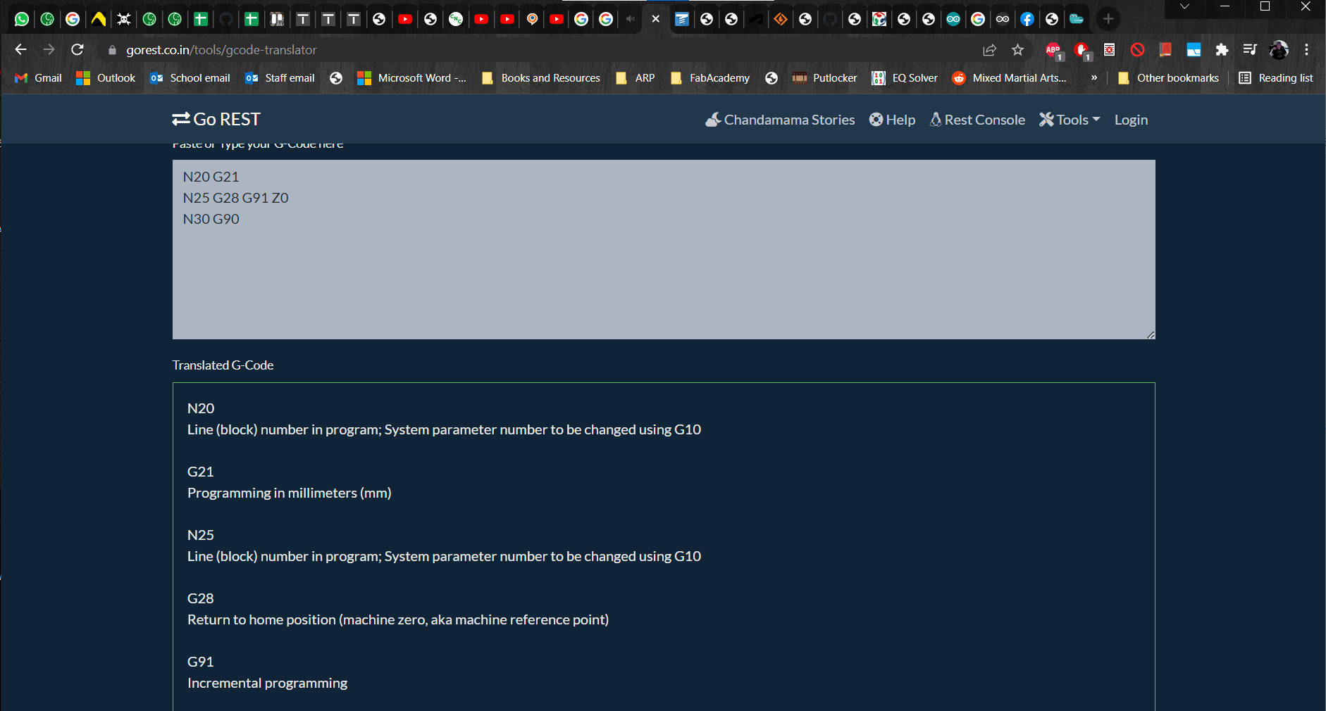
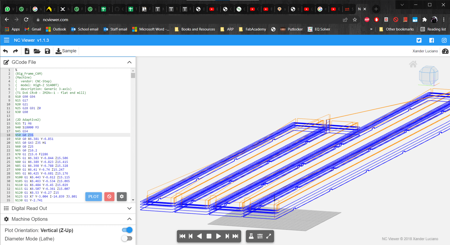
G-code Simulator
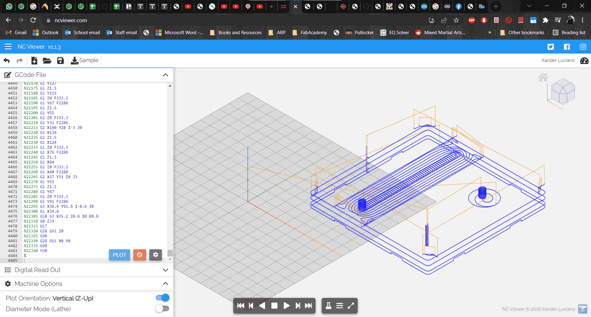
I also found a really useful and easy to use g-code simulator. With these two tools, I discovered that Fusion had in fact added a combination of lines that would have caused the tool to crash with the very first movement.
Fixed
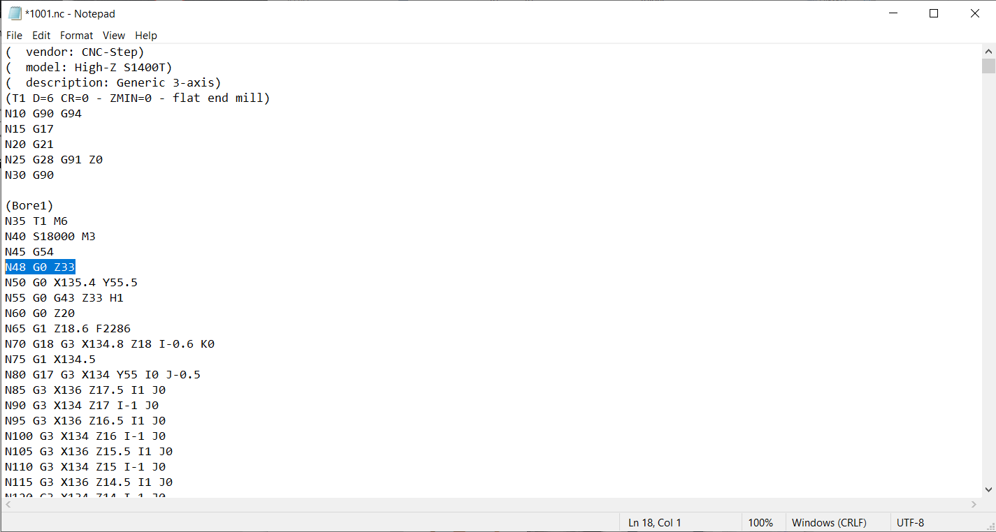
For some reason, the first movement command after the "homing dance" only contained instructions to move along the x- and y-axes. Since the z-axis was still at 0 at that point in the code, this would have caused the tool to collide with the workpiece. So I added a new line of g-code telling the machine to move up in the z-axis before executing the command in the x and y directions.
Cutting
Fixing the Parts to the Machine
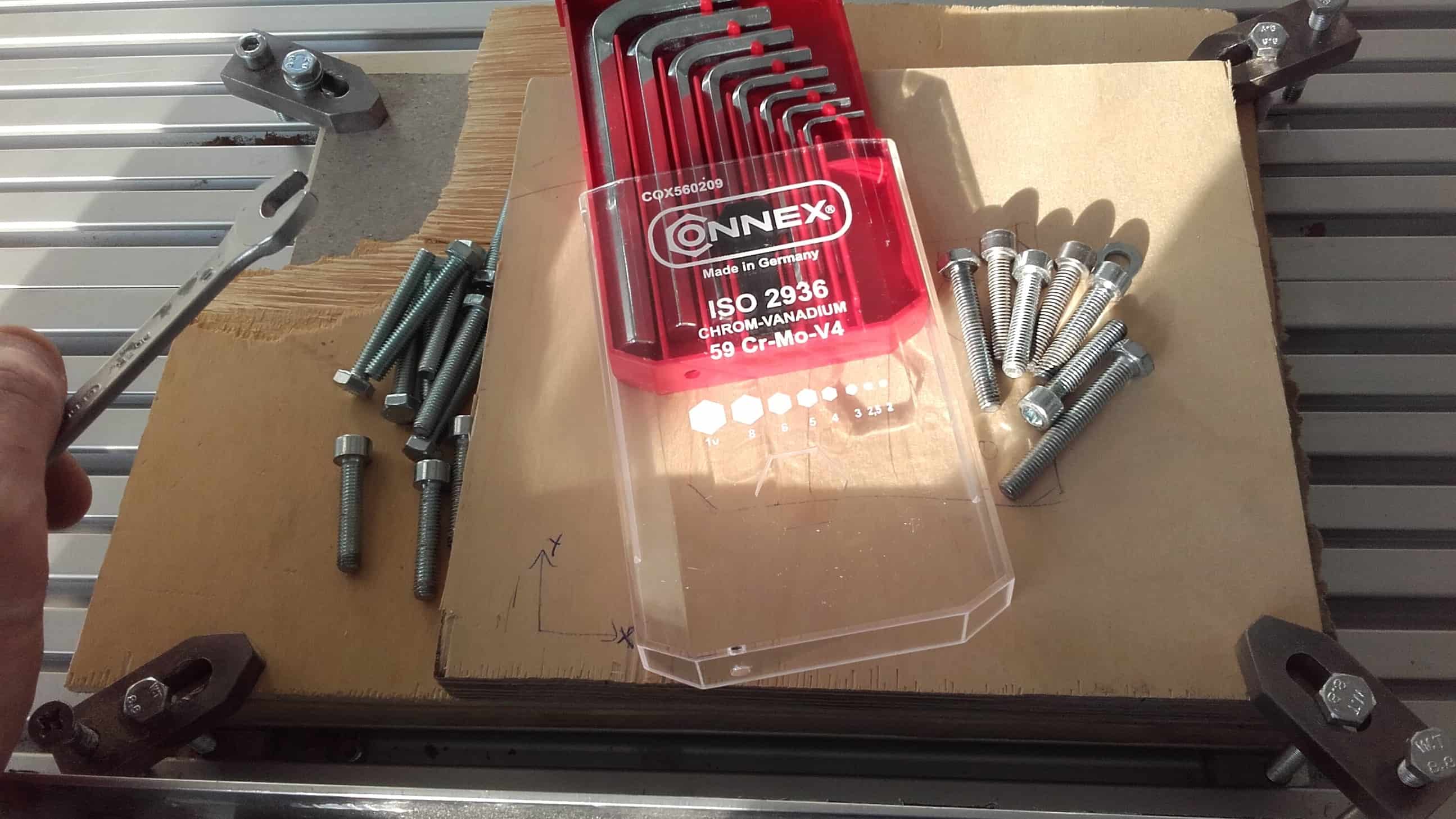
First, I attached the stock piece and the sacrificial material to the bed using clamps.
KineticNC
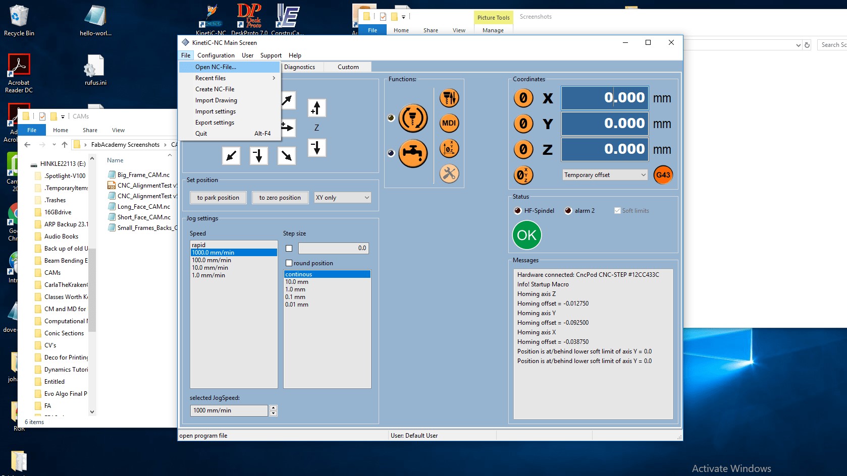
Then I opened up the KineticNC software and set the physical origin to that of the CAM using the Jog/Setup tab.
M3 Error
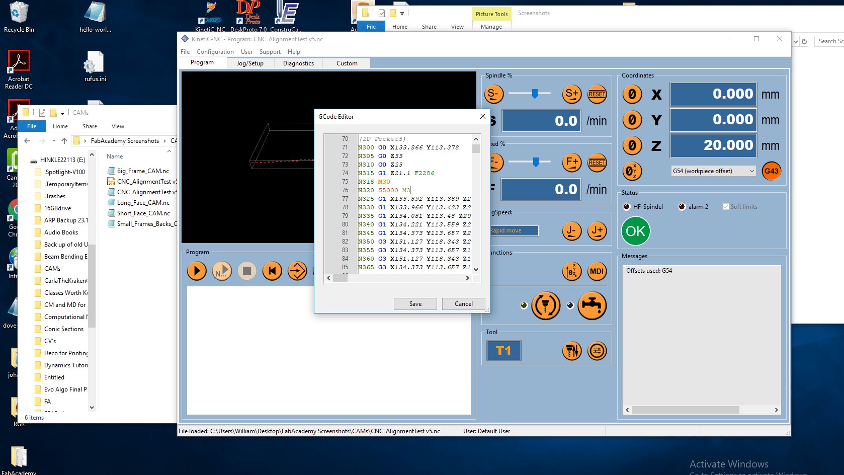
Then I discovered another minor issue with the g-code. The command "M3" gives instructions for changing the spindle speed from zero. It belongs at the beginning of the first operation, but if the spindle is already moving, then the command will generate an error. For some reason, the post processor added it to each operation for this CAM so I had to remove it from all but the first.
Play
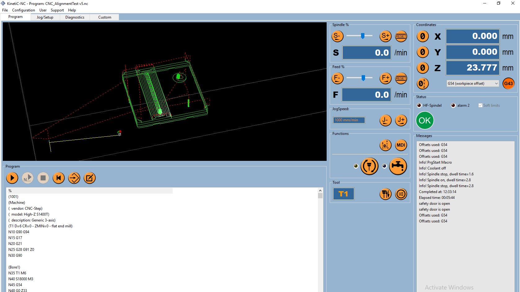
The g-code was finally looking good and I was ready to cut, so I went over to the Program tab and clicked the Play button. After a trial run cutting only air, I inserted the tool back into the collet and finally started actually cutting wood.
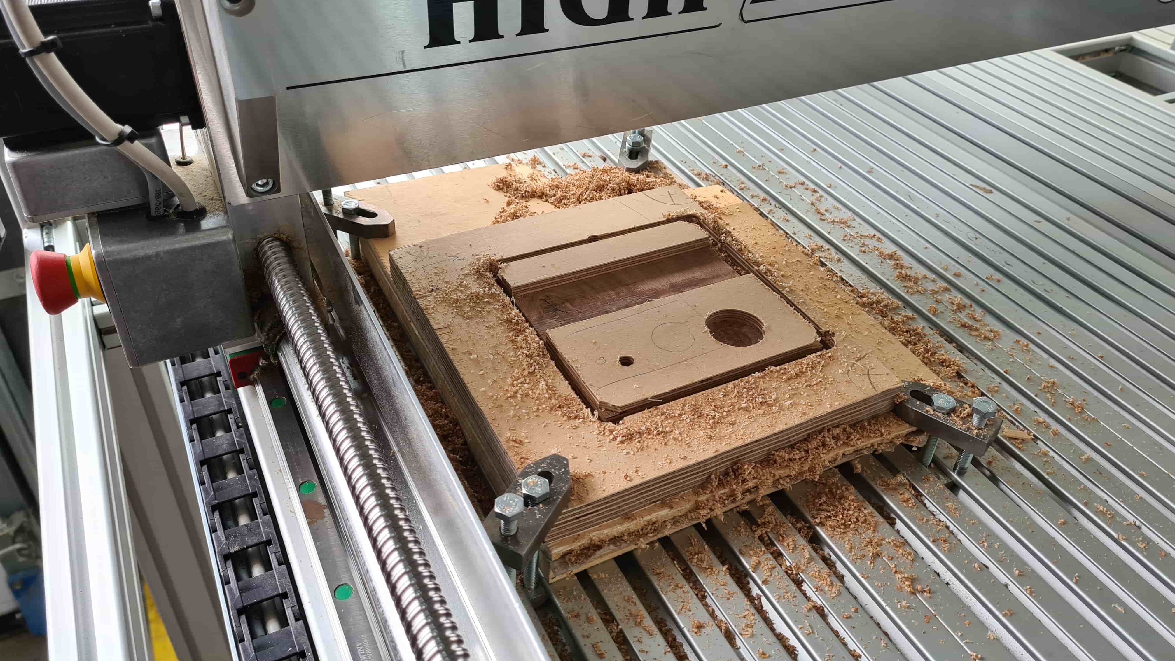
Cutting
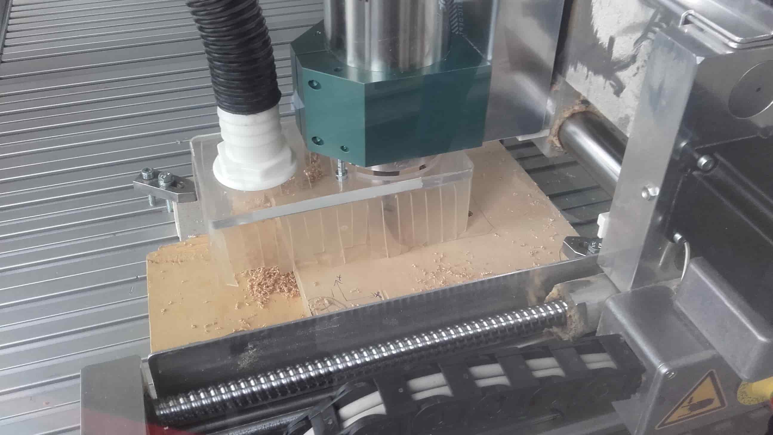
The machine did its thing while I carefully watched with my hand on the Emergency Stop button.
Success
The part came out ok.
Not Great

Just ok.
Not Terrible
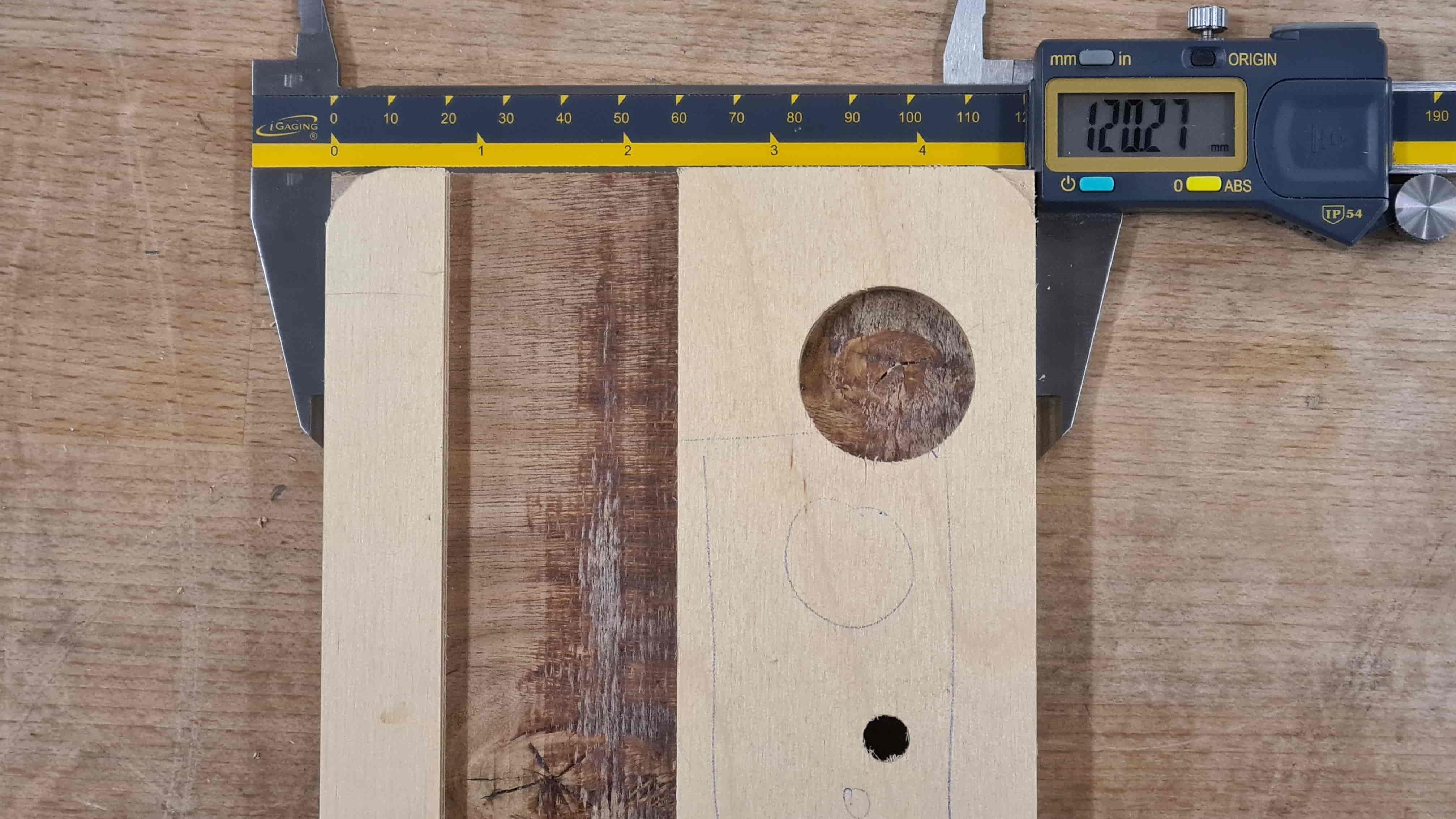
But really not so bad.
Success
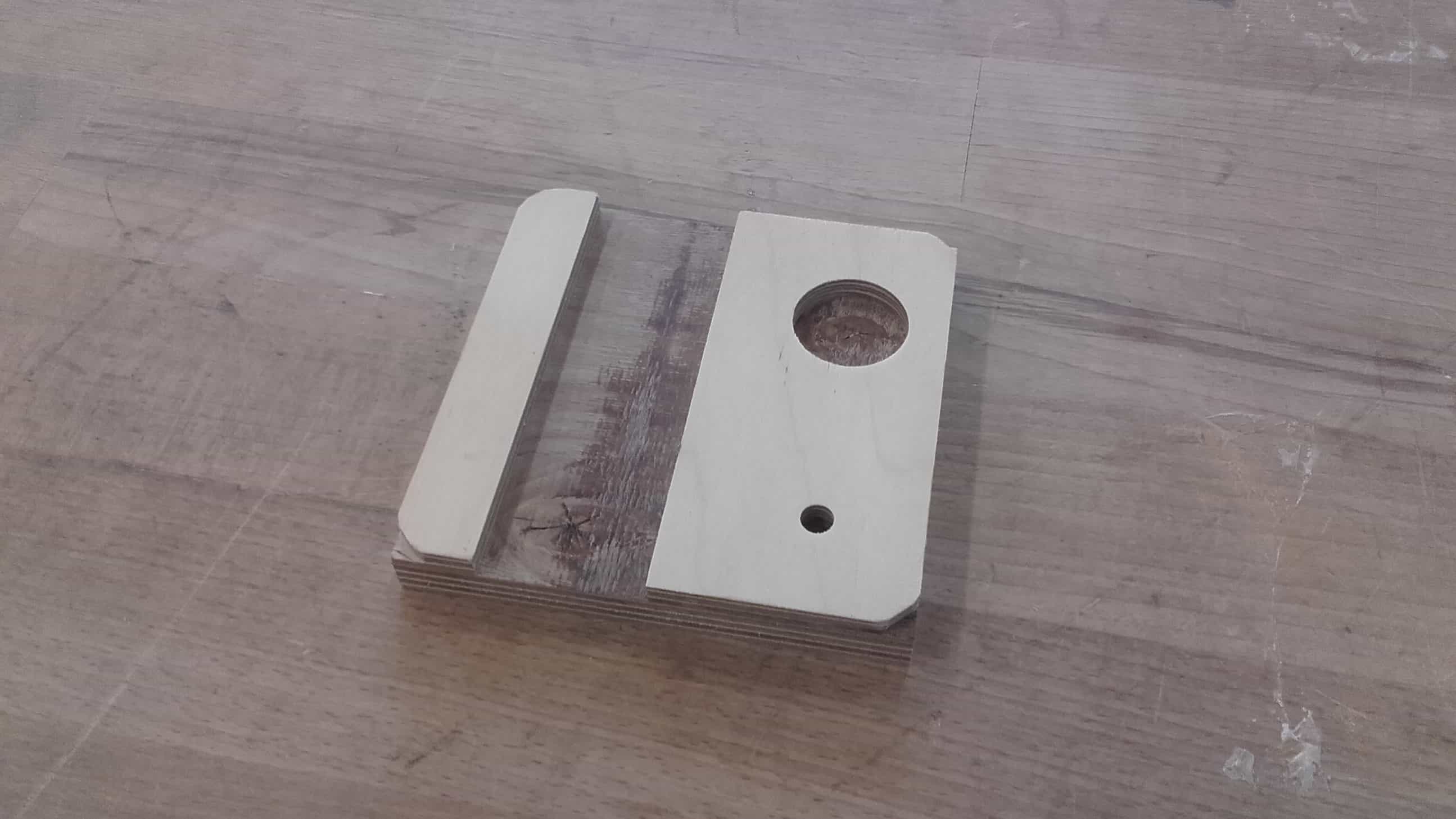
Here it is after sanding it a bit and cleaning up the tabs.
CAMs for My Final Project
Back in Fusion 360
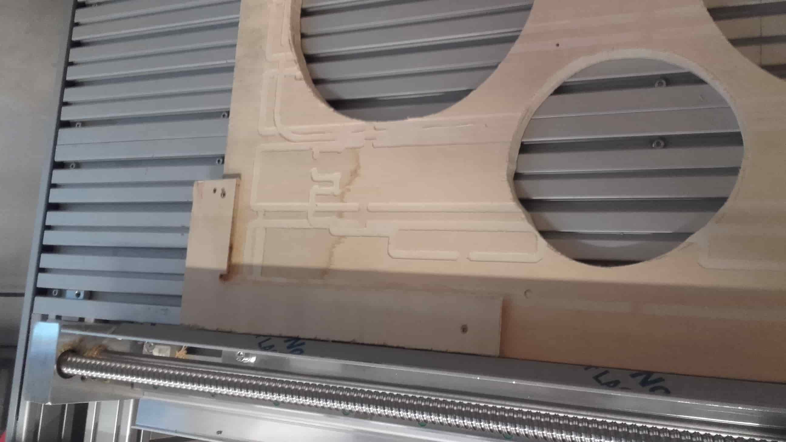
Learning from the Group Project
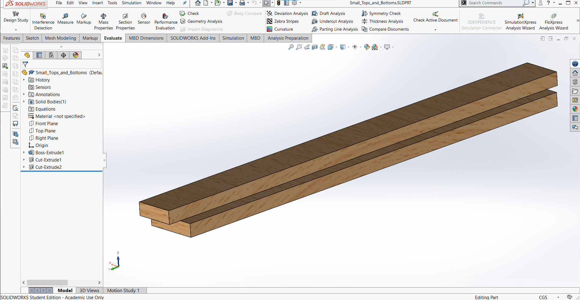
When creating the tool profile for our library, we used the spindle speed and feed rate that was recommended by the manufacturer of the tool. The cut worked well in straight areas, but since our CNC machine isn't super rigid, there was a bit of overshoot on the corners where the tool changed direction (see image above). So I made another configuration for the tool and reduced both by 20%. This solved the problem so I used this configuration for all of my parts. When I started making the CAMs, for some reason, It didn't occur to me to cut all the parts at once right away, so at first, I set out to create different CAMs for different pieces, with the intention being to run them as many times as I needed to attain the quantity I wanted. After creating the operations, it occurred to me to cut several pieces at once so you will see that progression here. It was also nice to learn that Fusion can upload and open SolidWorks part files with no problems.
New Project
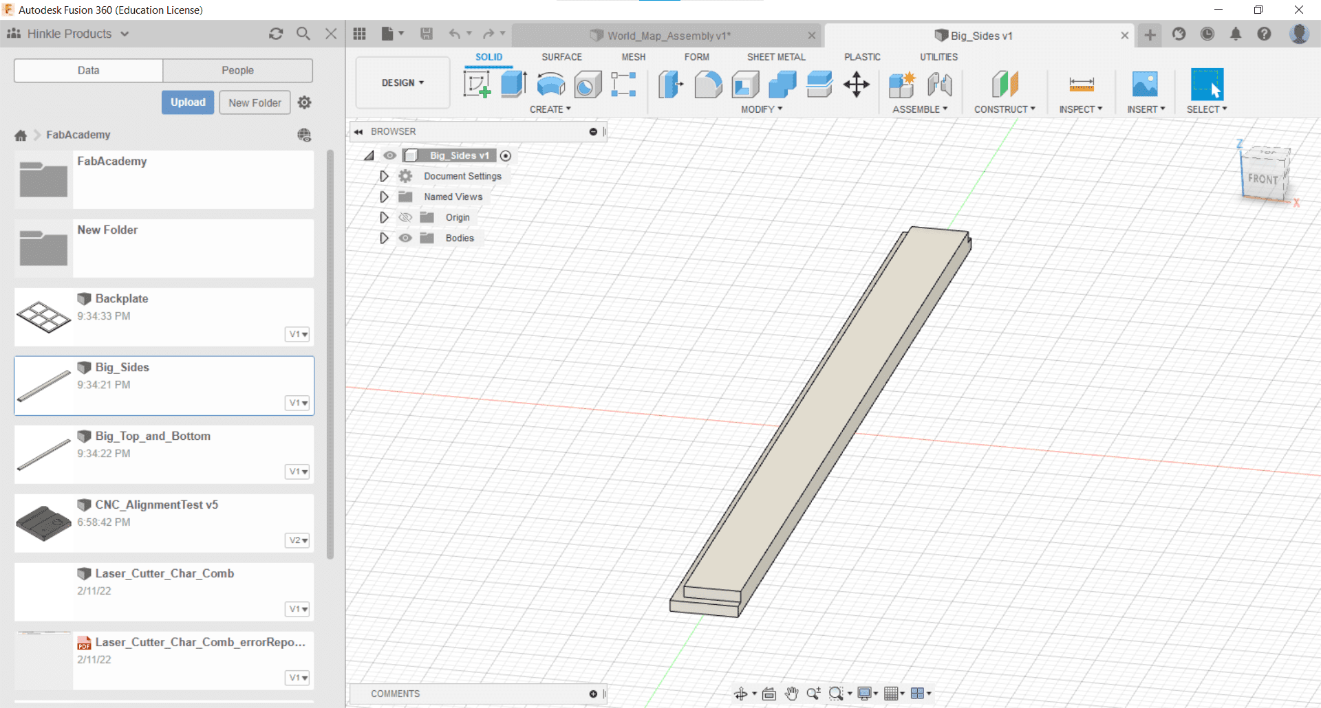
I started by opening up one of the parts of my outer frame in Fusion 360.
New Setup
I created a New Setup from the Setup tab by defining the origin and the stock I was intending to use.
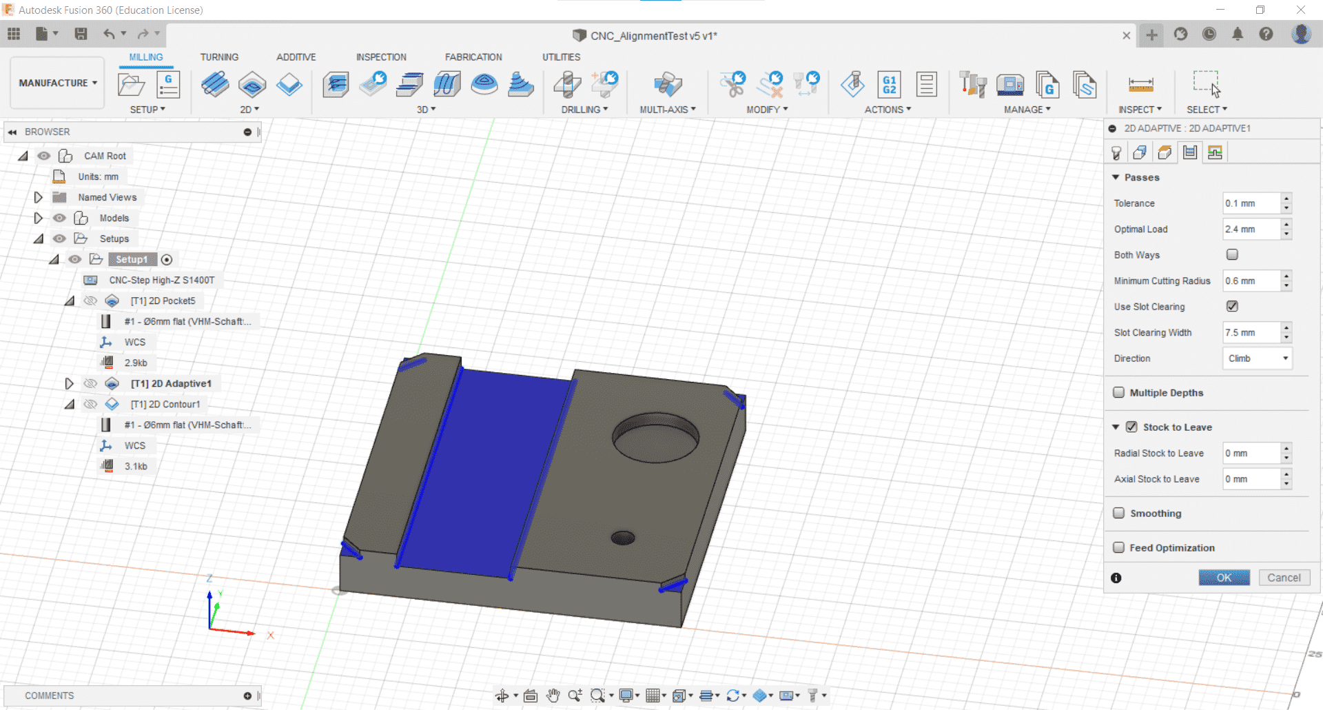
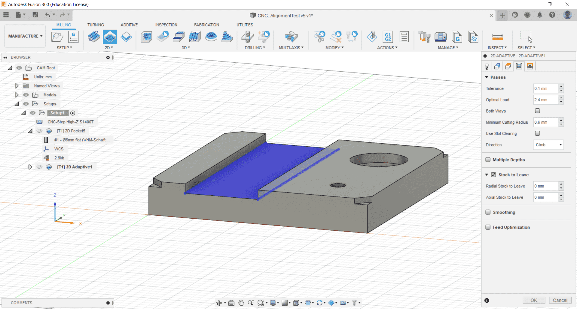
2D Adaptive Clearing
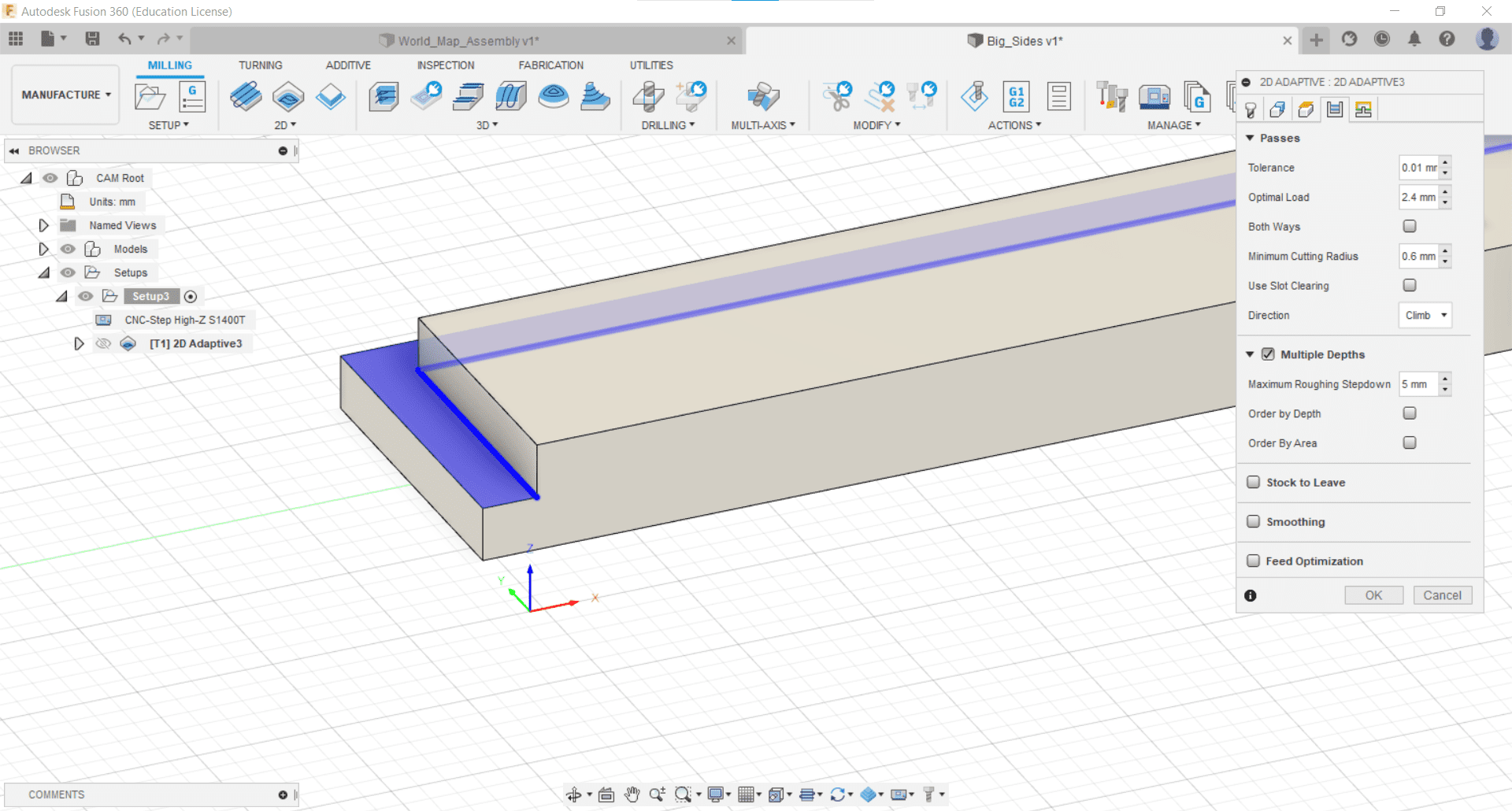
I thought the 2D Adaptive Clearing operation in the 2D tab would be best for cutting my grooves so I selected the tool with the new 80% configuration and the geometry I wanted to cut, and then chose multiple passes with a roughing depth of 5 mm.
Defaults
I kept the rest of the parameters at their default values.
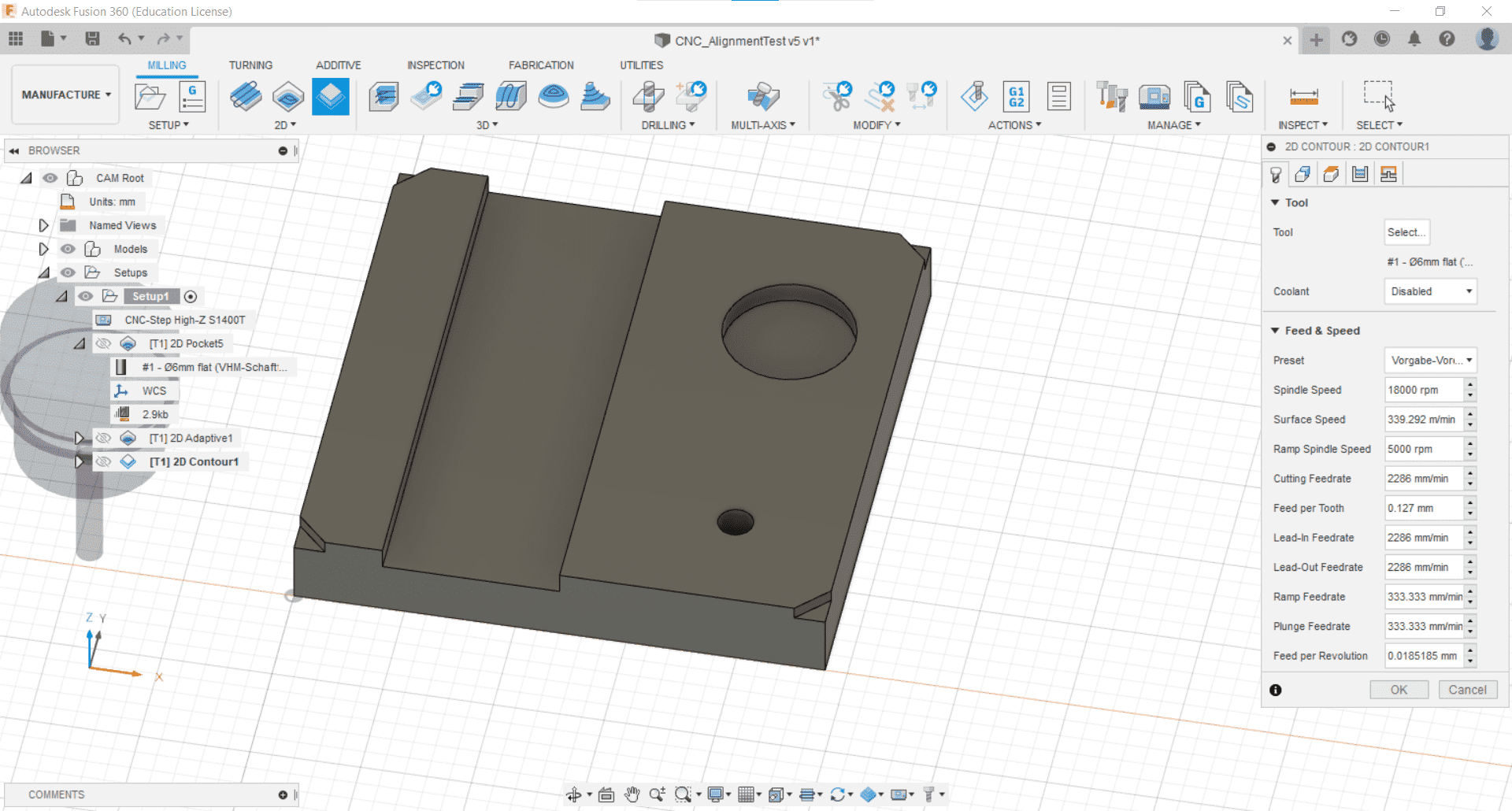
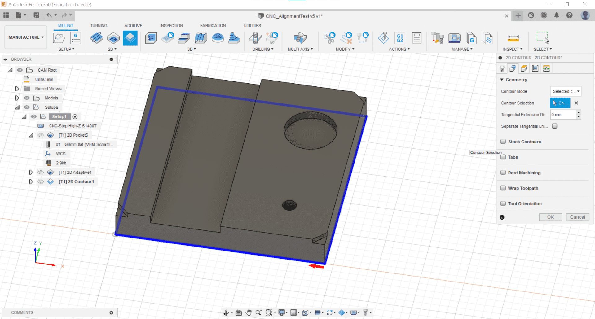
Contour Cut
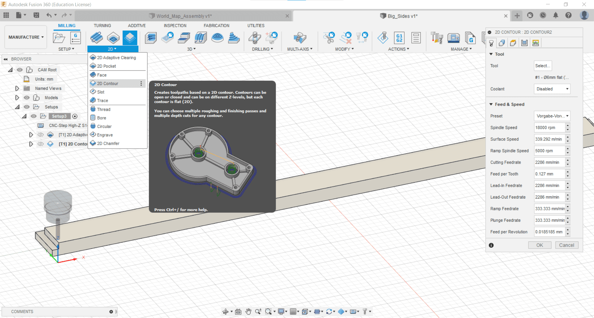
And moved on to making the Contour Cut operation from the 2D tab.
Multiple Passes
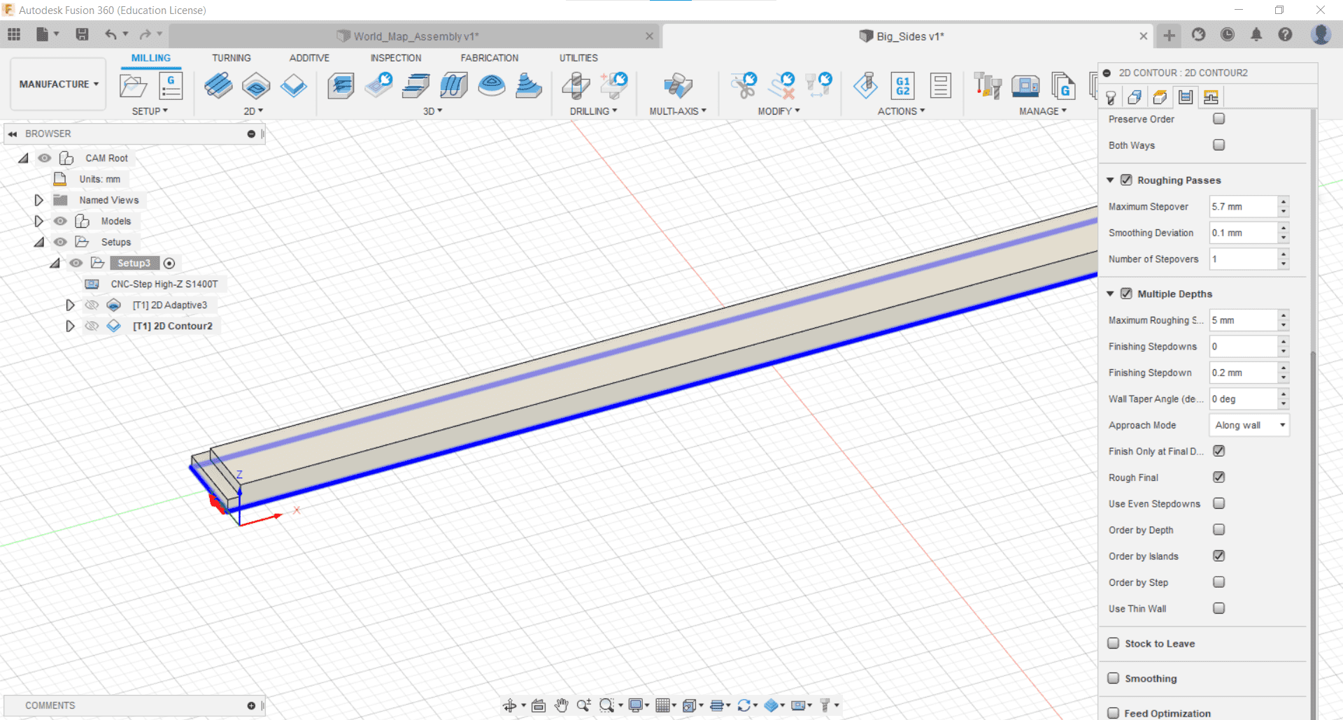
Once again, I went with 5 mm passes, but this time I also used 0.2 mm Stock to Leave in the radial direction and -0.3 mm in the axial direction. I also went with 6 mm x 1.5 mm tabs every 200 mm.
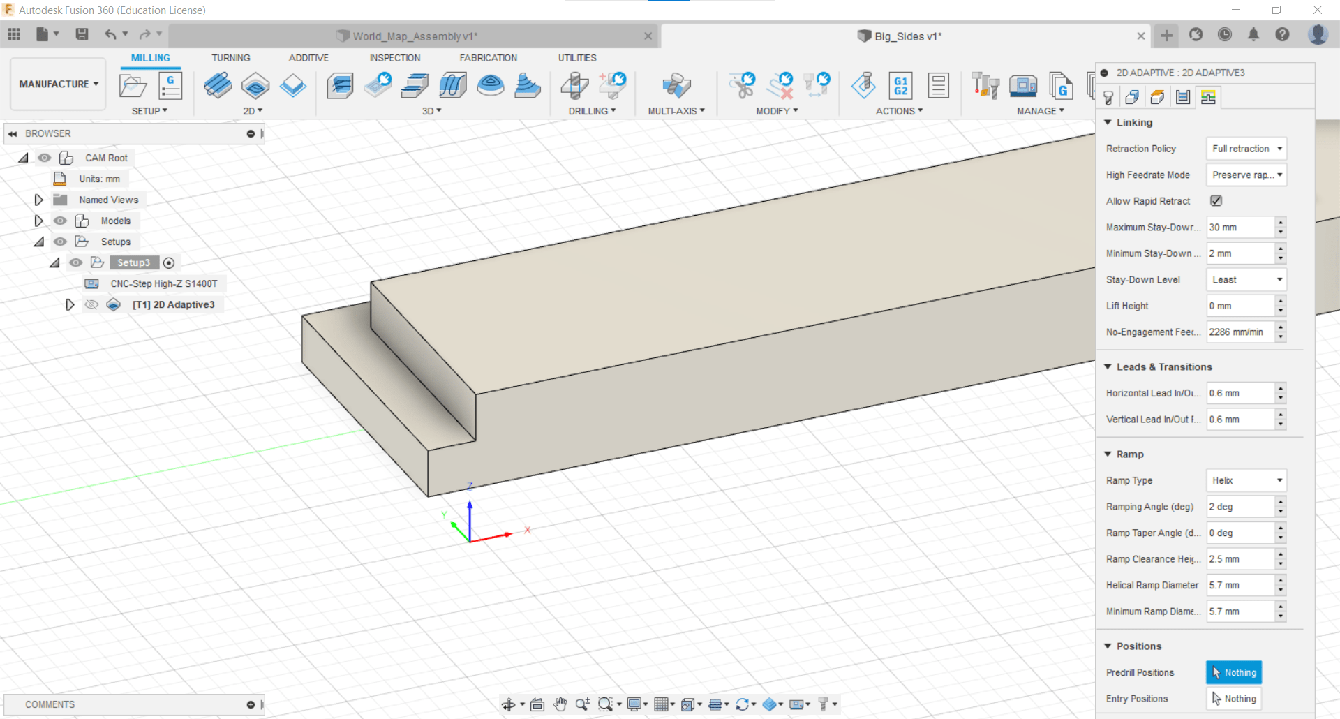
Linking
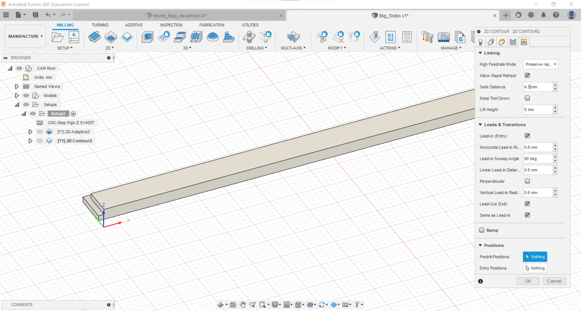
Then I changed the Minimum Safe Distance in the Linking menu to 4.5 mm so it didn't conflict with my 5 mm passes...and kept the rest of the parameters at their defaults.
Action
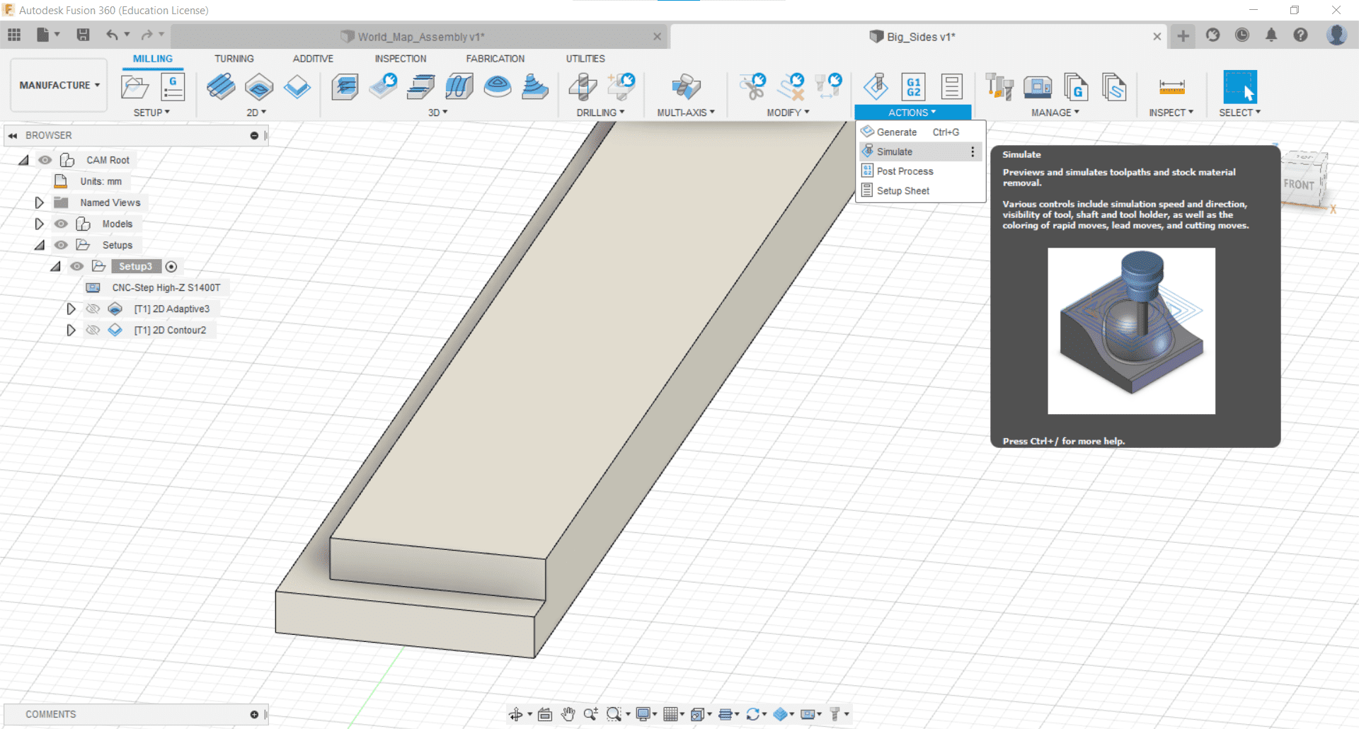
Then in the Action tab...
Simulate
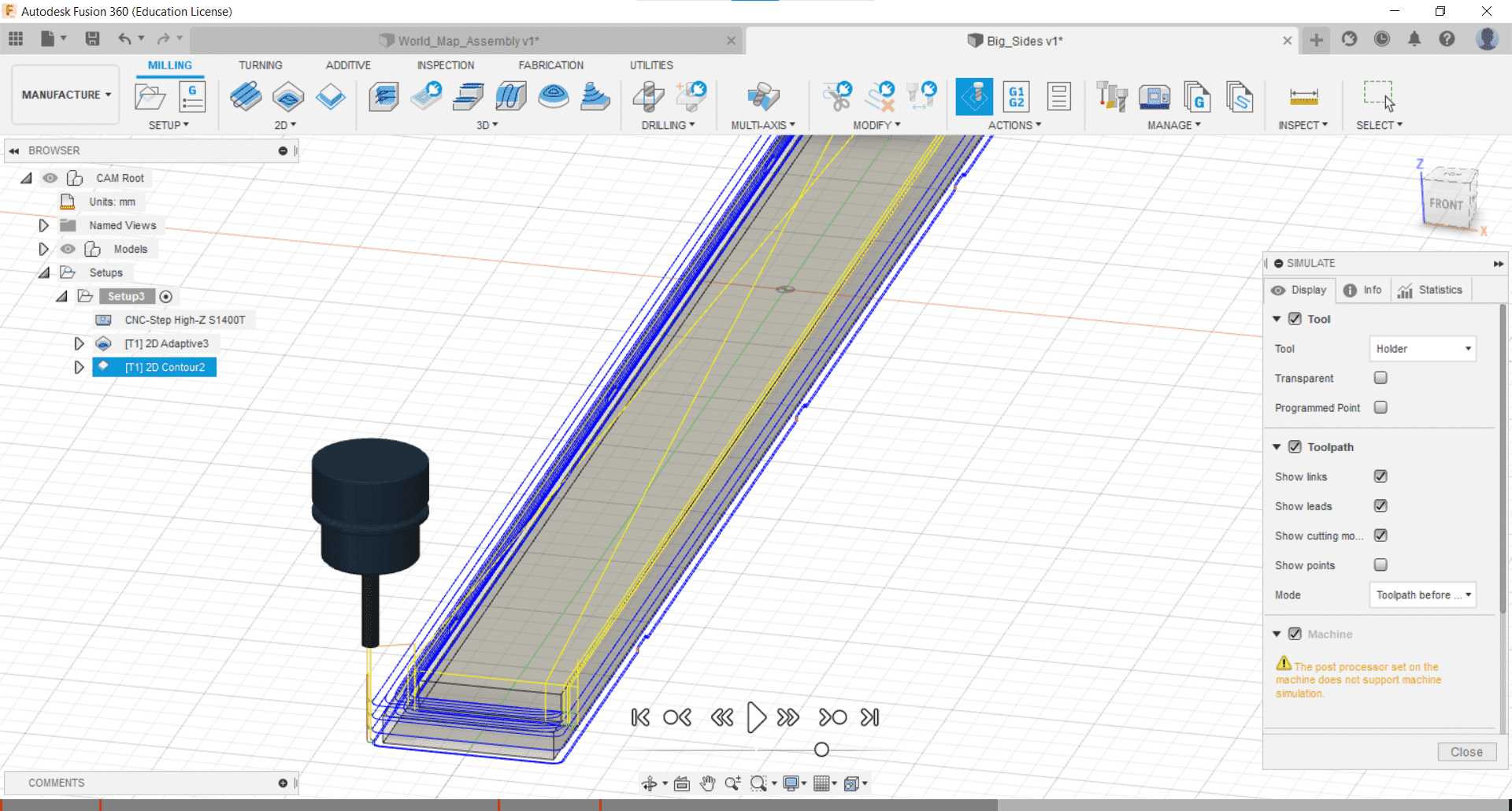
...I used the Simulate tool to simulate the tool paths.
Post Process
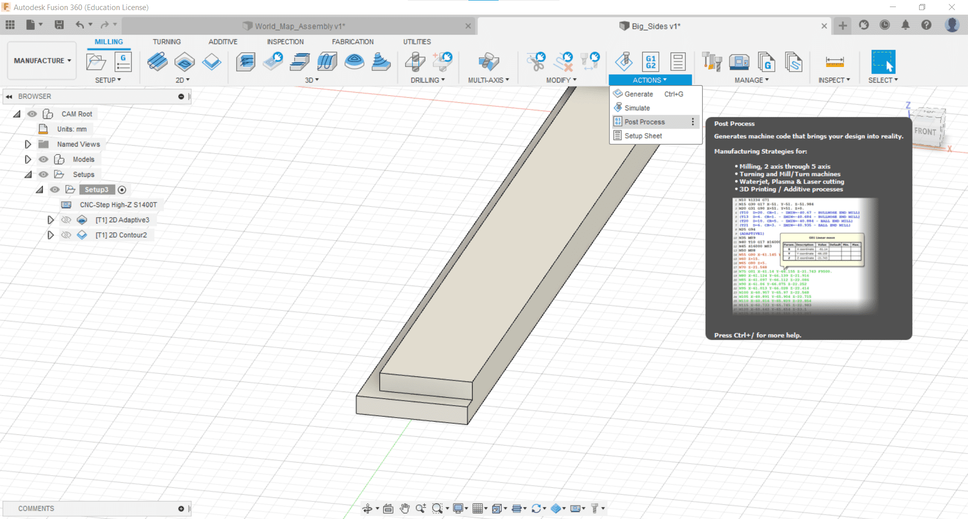
I went to the Action tab once more to to the Post Processing tool to create the gcode...
Derp
...and that's when it occurred to me that I could make CAMs for as many pieces as would fit in the bed at once and reduce my workload significantly.
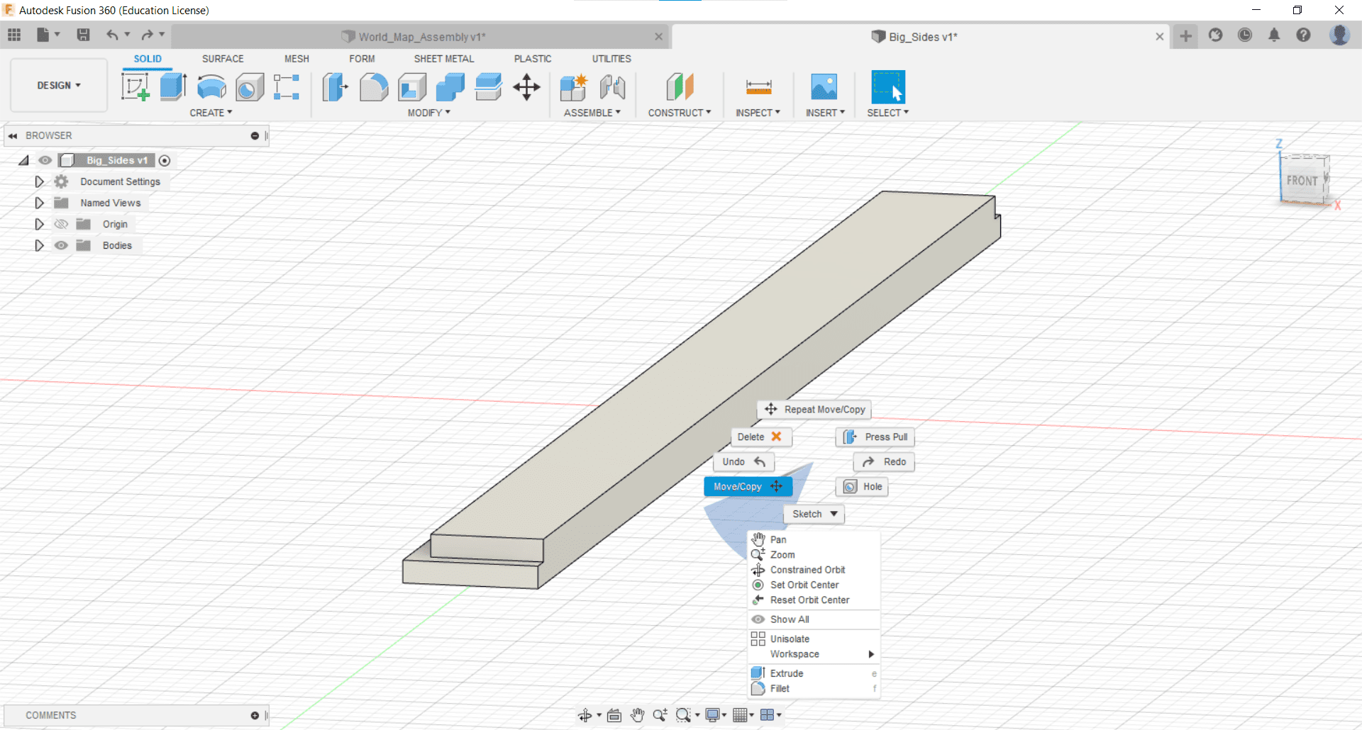
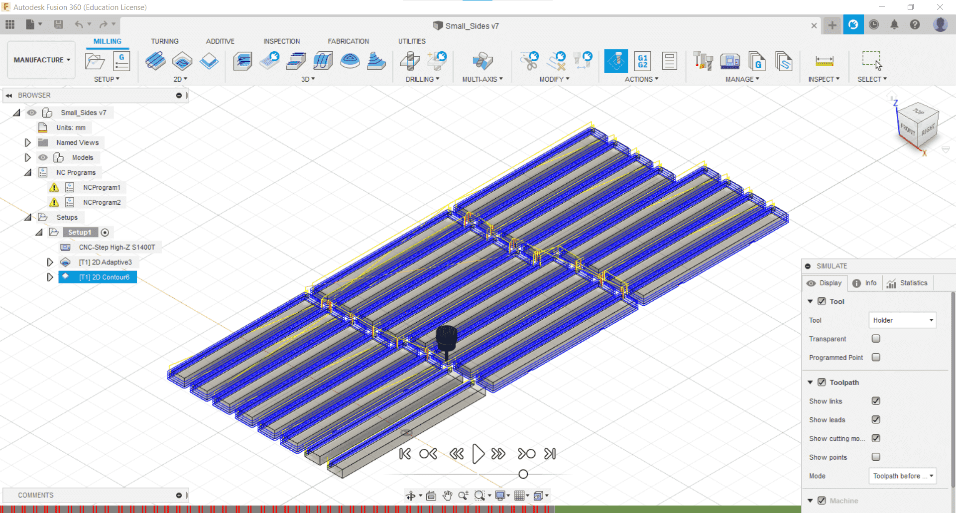
Copies
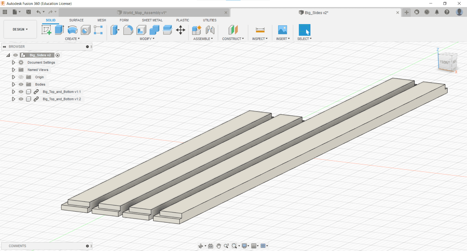
So I brought in all the parts of the outer frame at once using the Move/Copy tool (found by right-clicking the part) and by Importing Into Current Model (found by right-clicking the part in the Data Panel).
Updating Stock
And then redefined my stock to a larger piece that would fit everything.
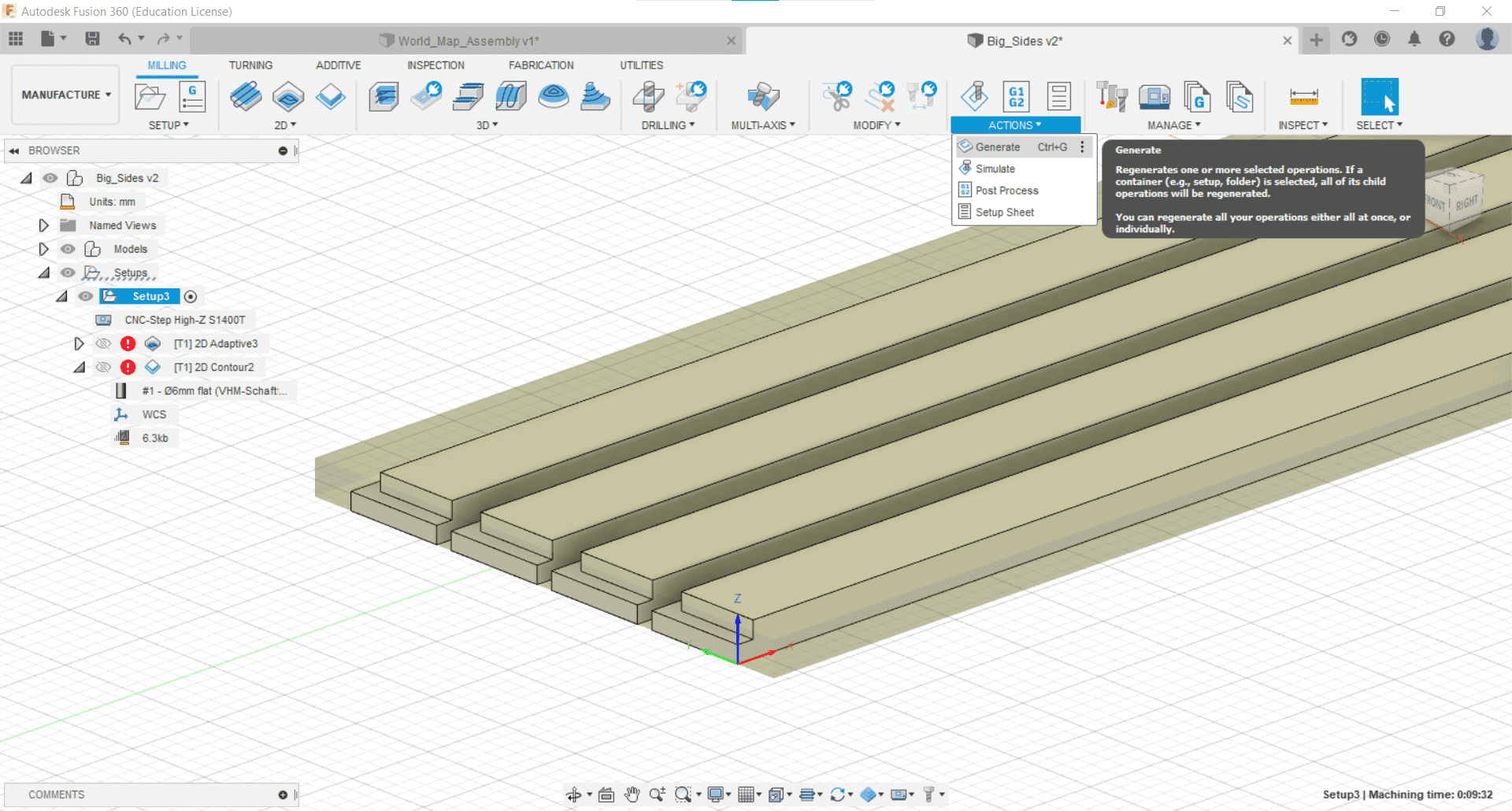
Updating Operations
The cutting operations were also easy to update. I basically just had to reselect my geometry.
Simulate and Post Process
I simulated the cut again and when I was satisfied that it was correct, I generated the gcode.
CAM for Small Frame Parts
Not Like the Others
The parts for the smaller frames had grooves on both sides, so I was going to need a CAM and a setup for each side.
Extrude the Groove Away
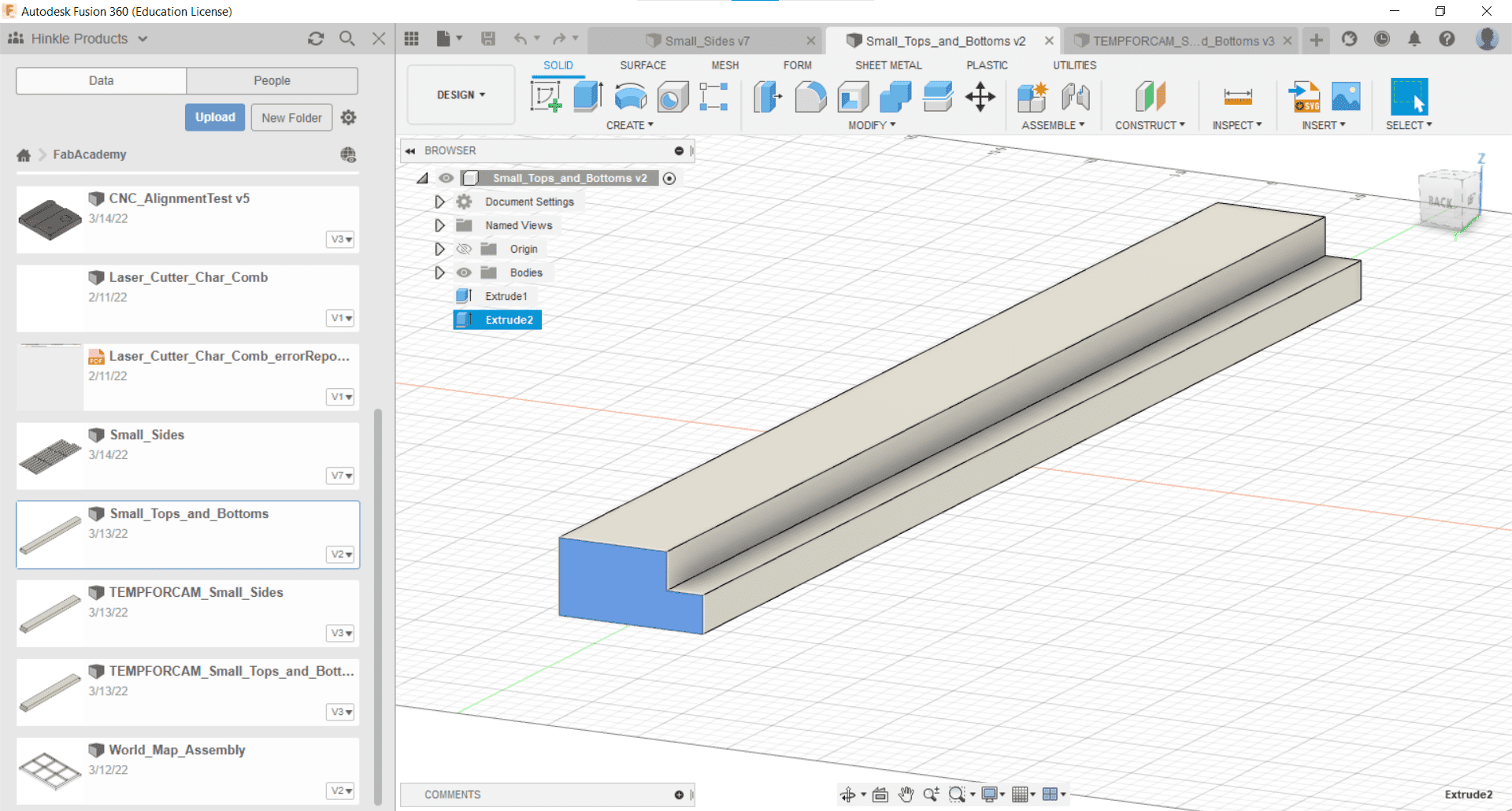
I had difficulty defining the contour cut, so I just extruded the gap since I was making two CAMs anyway.
Faces
I made the CAMs for cutting the faces of the parts in the same way I had with the frames.
Backs
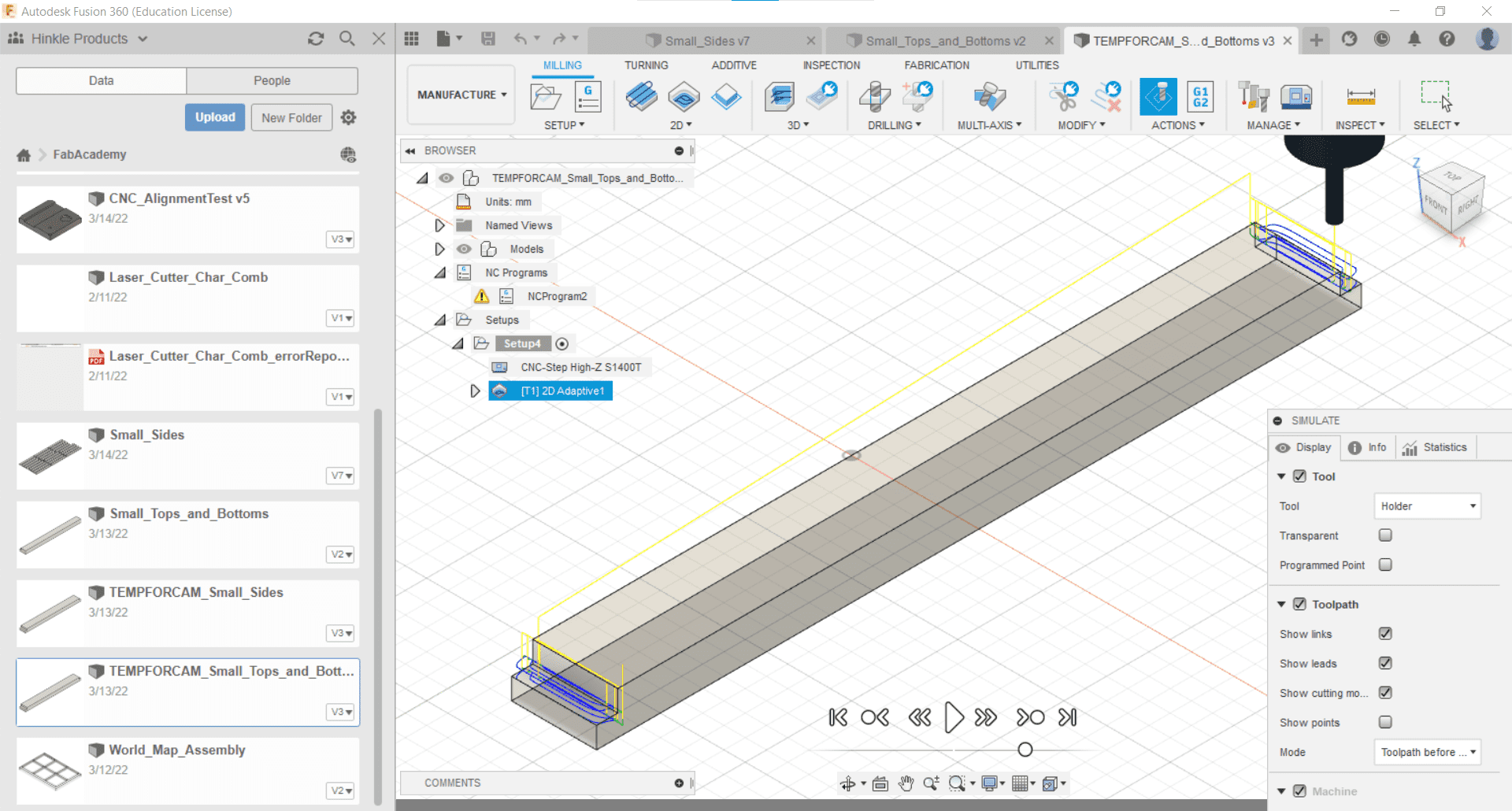
And then I made a CAM to cut the backs. This only had one part, and I would repeat the setup for all of them.
CAM for Backplate
Too Big
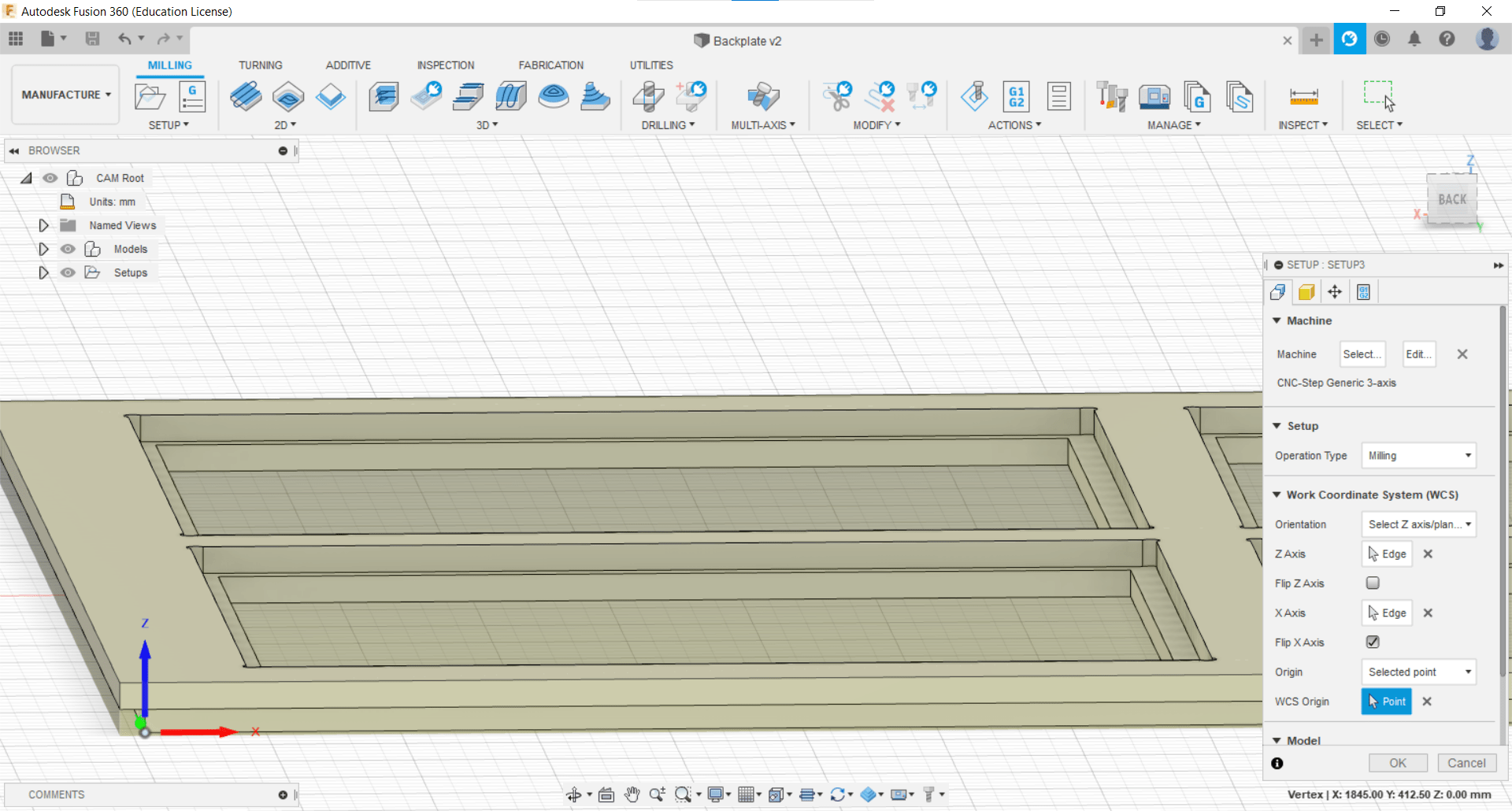
The maximum cut for our machine in the y-direction is 80 cm, and of course my part is 84.5 cm...so I had to get creative. I cut the outside dimensions using a circular saw, and then I cut the outer groove using a handheld router.
Machine Configuration
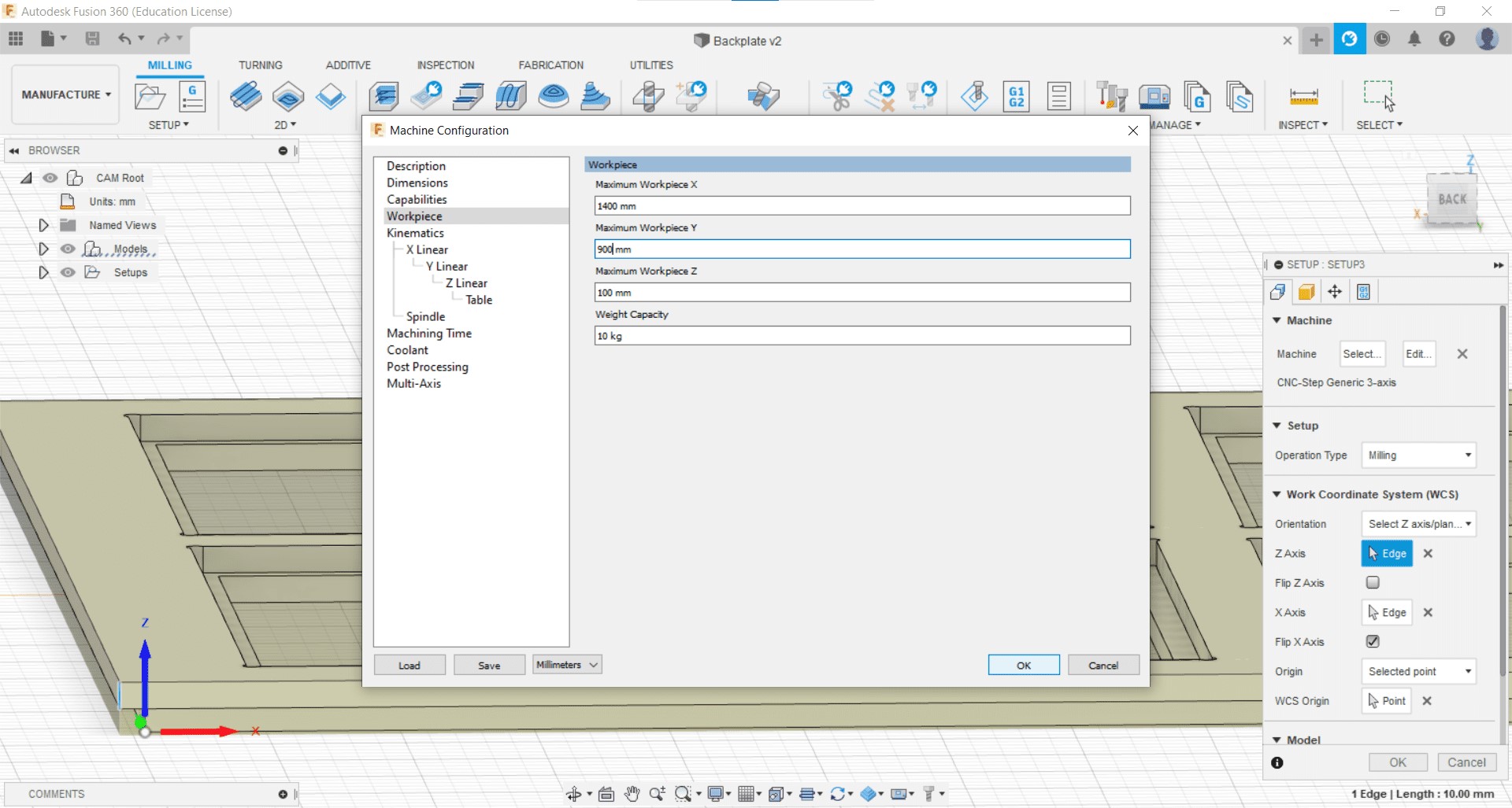
This allowed me to use the corner of the new groove as my origin and to get my inside cuts at a distance of 78.5 cm in the y-direction. All I had to do was to change the machine settings to allow a larger workpiece.
2D Pocket
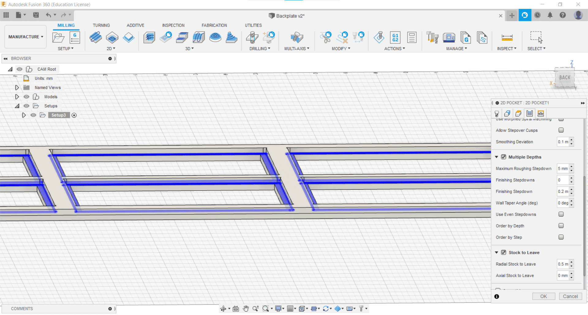
I then created the operations for a 2D Pocket cut...
Contour Cut
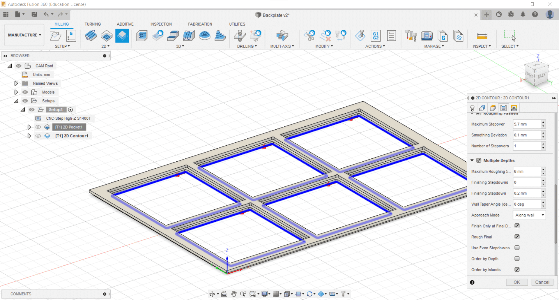
...and the Contour Cut the same as I had for the other CAMs.
Double Checking the Gcode
Fixed
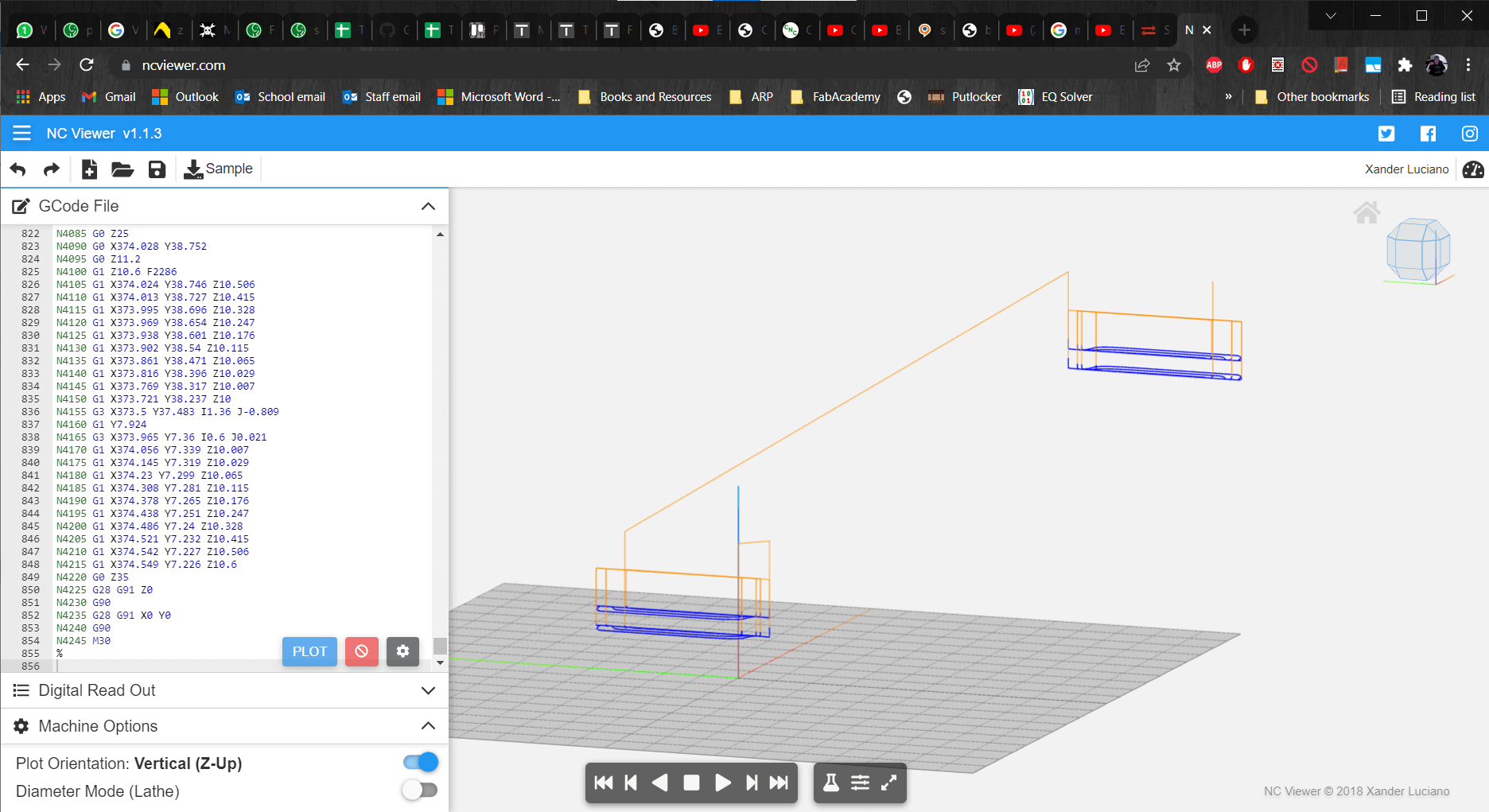
And once again, for each of them, I had to add a line moving up in the z-direction to prevent the tool from colliding with the stock in the first move.
Cutting and Assembly
Outer Frame
I started by cutting the outer frame.
So Far, So Good
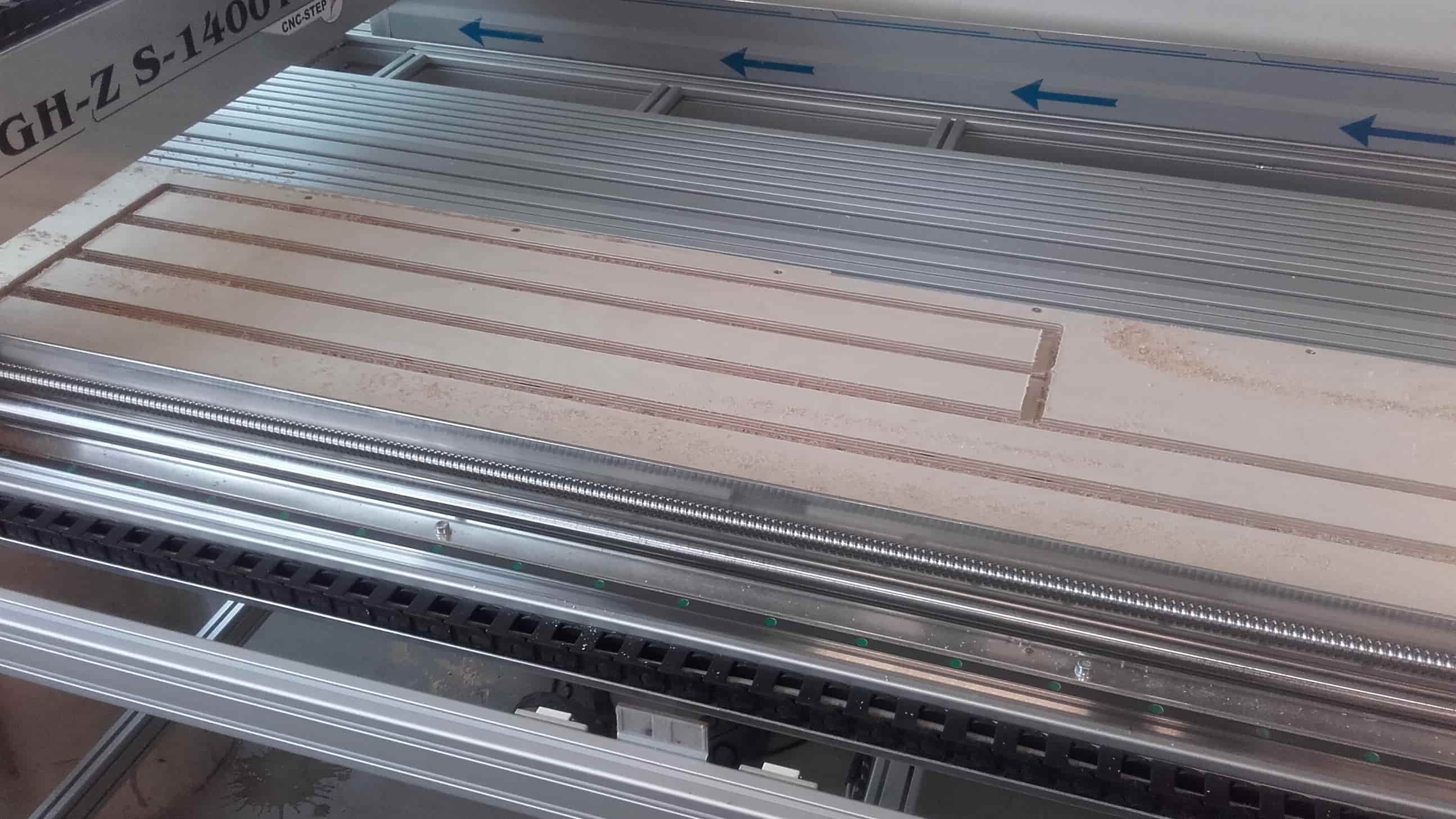
It could not have gone much better. The machine sounded happy and the parts came out nice.
Or Not
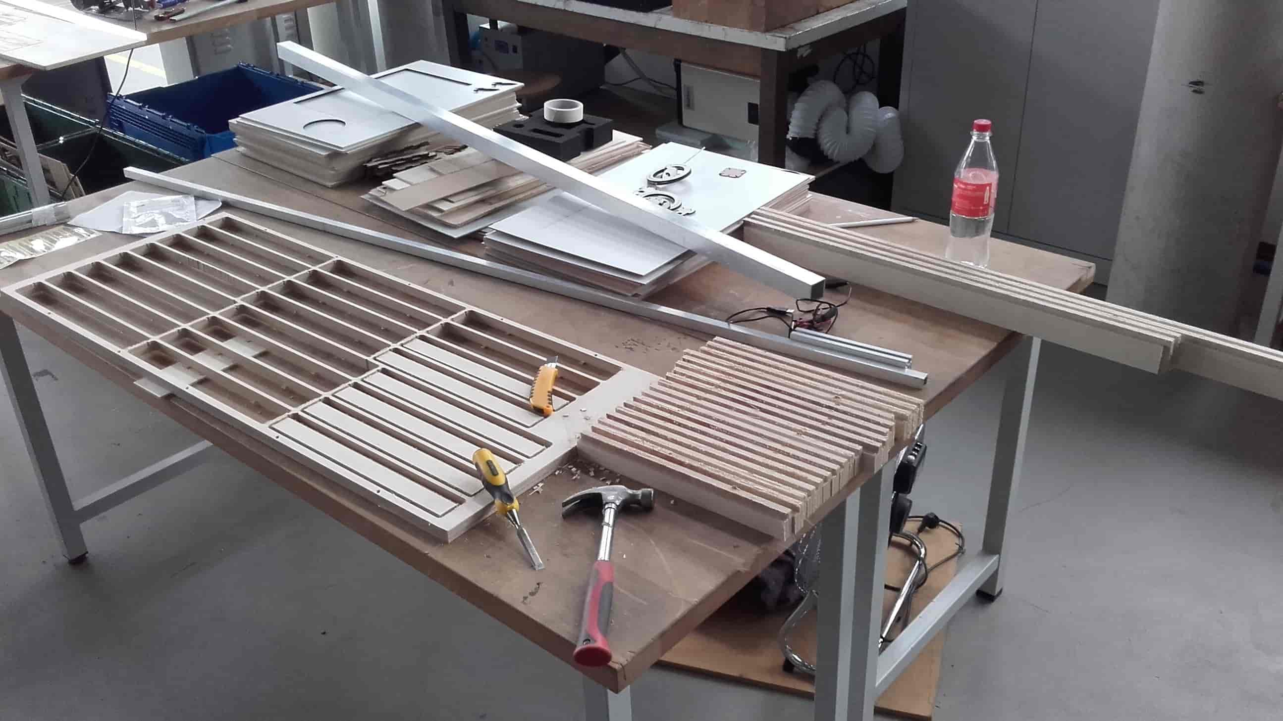
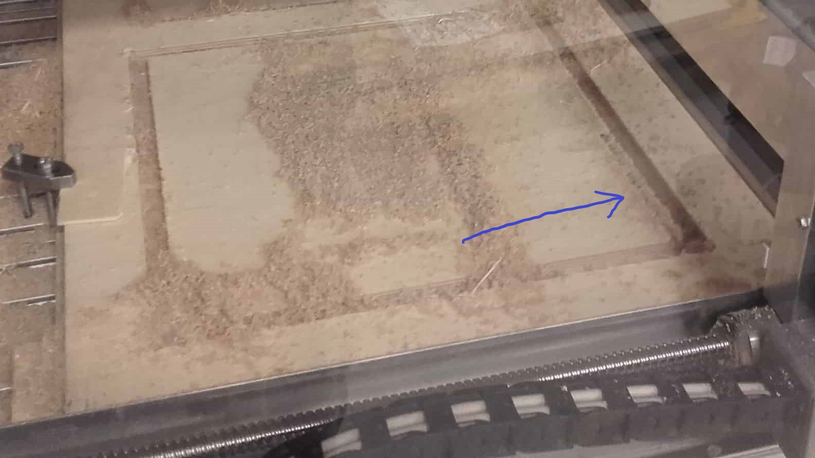
Then I cut the parts for the small frame. Even though everything about the CAMs and setups was the same, many of the tabs broke during this cut...
Not So Nice

...so the pieces moved around in the slots and several came out damaged and ugly.
Cleanup on Aisle 3
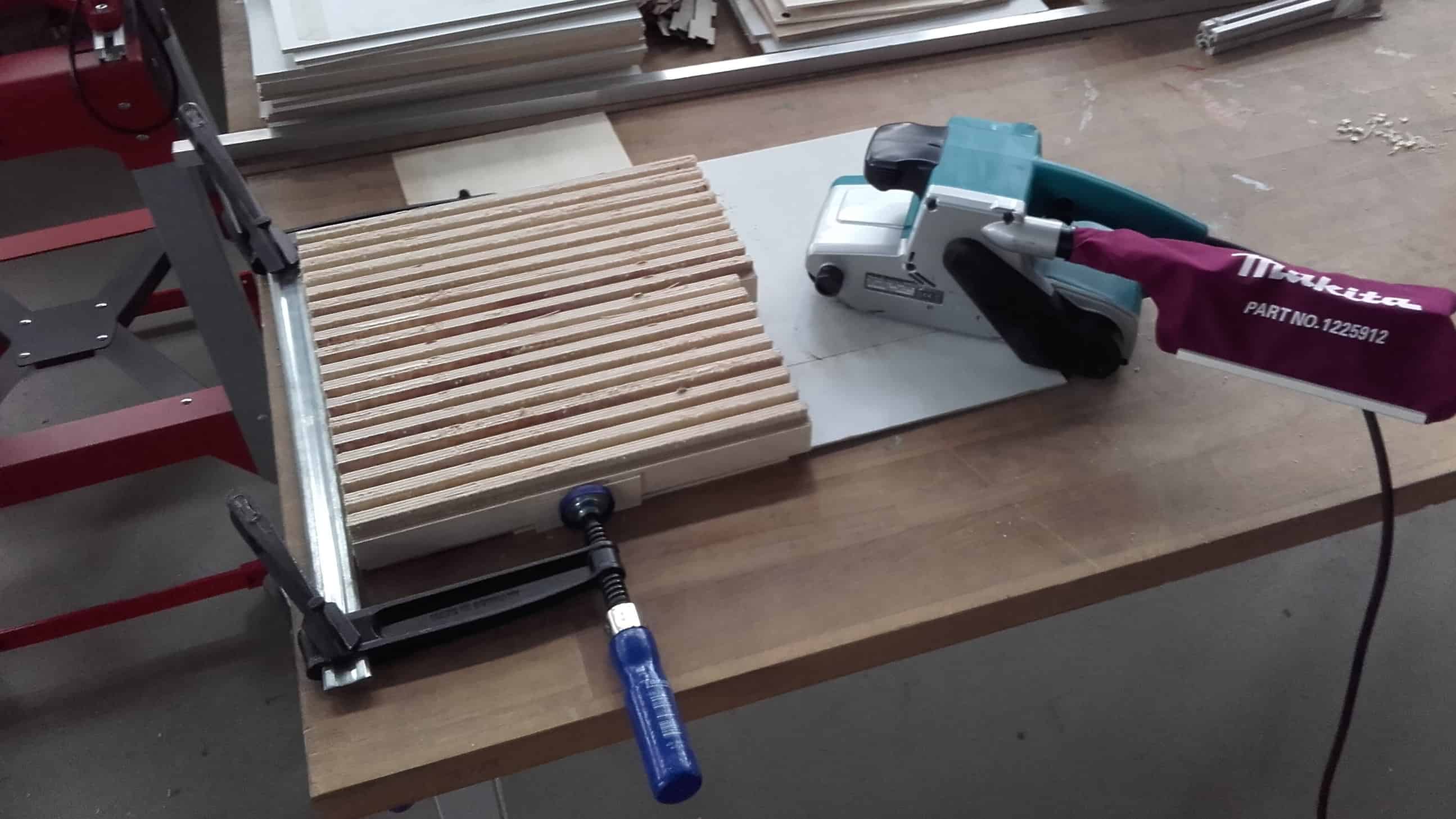
Even though they were rough, the dimensions were pretty decent so I clamped them all together and hit them with a belt sander to make them all even, and then hand sanded them for hours to make them look clean.
Cutting the Back Sides

Then I put them back into the CNC machine one by one to cut the back sides. The cut only took two minutes each so even with all the setups, the process only took a couple hours. Unfortunately, even though I repeated the process 24 times, I managed to forget to take any pictures. 😬
Milling My Origin
Since I was only cutting out the middle of the part, the setup for the backplate had to be perfect. I started by cutting a piece of sacrificial material I could butt up against and know with confidence that it was on the machine y-0. I also adjusted the tabs to be 2.5 mm high, instead of 1.5 like the other CAMs in order to avoid a repeat of the other job.
Oops
I nailed the y-axis, but even with the 2.5 hour setup on this part, I still got off on the x. Fortunately I was paying close attention and noticed it on the first cut before it cut into any areas that were permanent. I made the slight adjustment that was needed and restarted the job.
Most Good
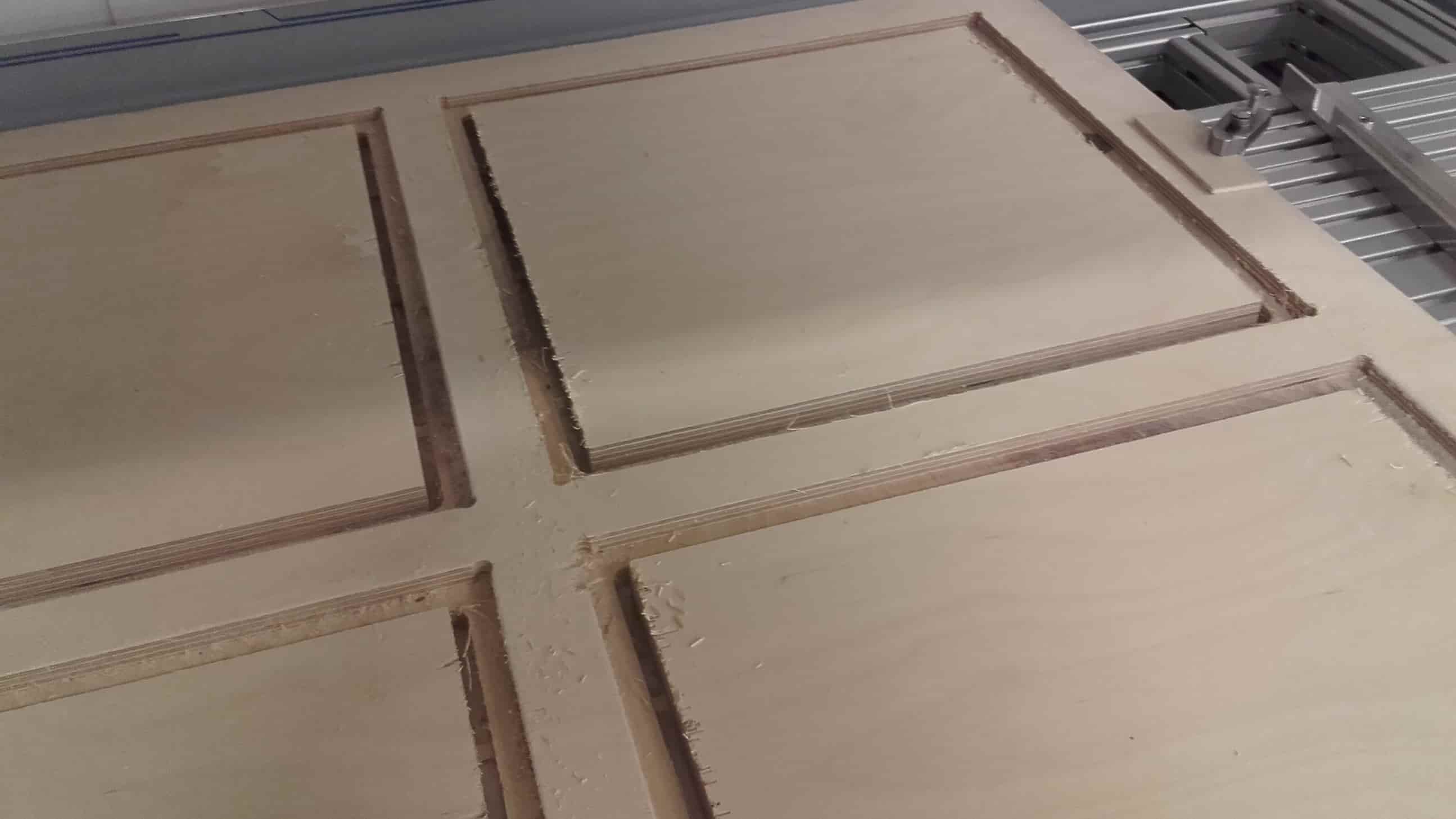
This time, everything went very well. The cuts all are exactly where they should be and the chip-out is pretty minimal.
More Sanding
I carefully cut the tabs and sanded the parts once more.
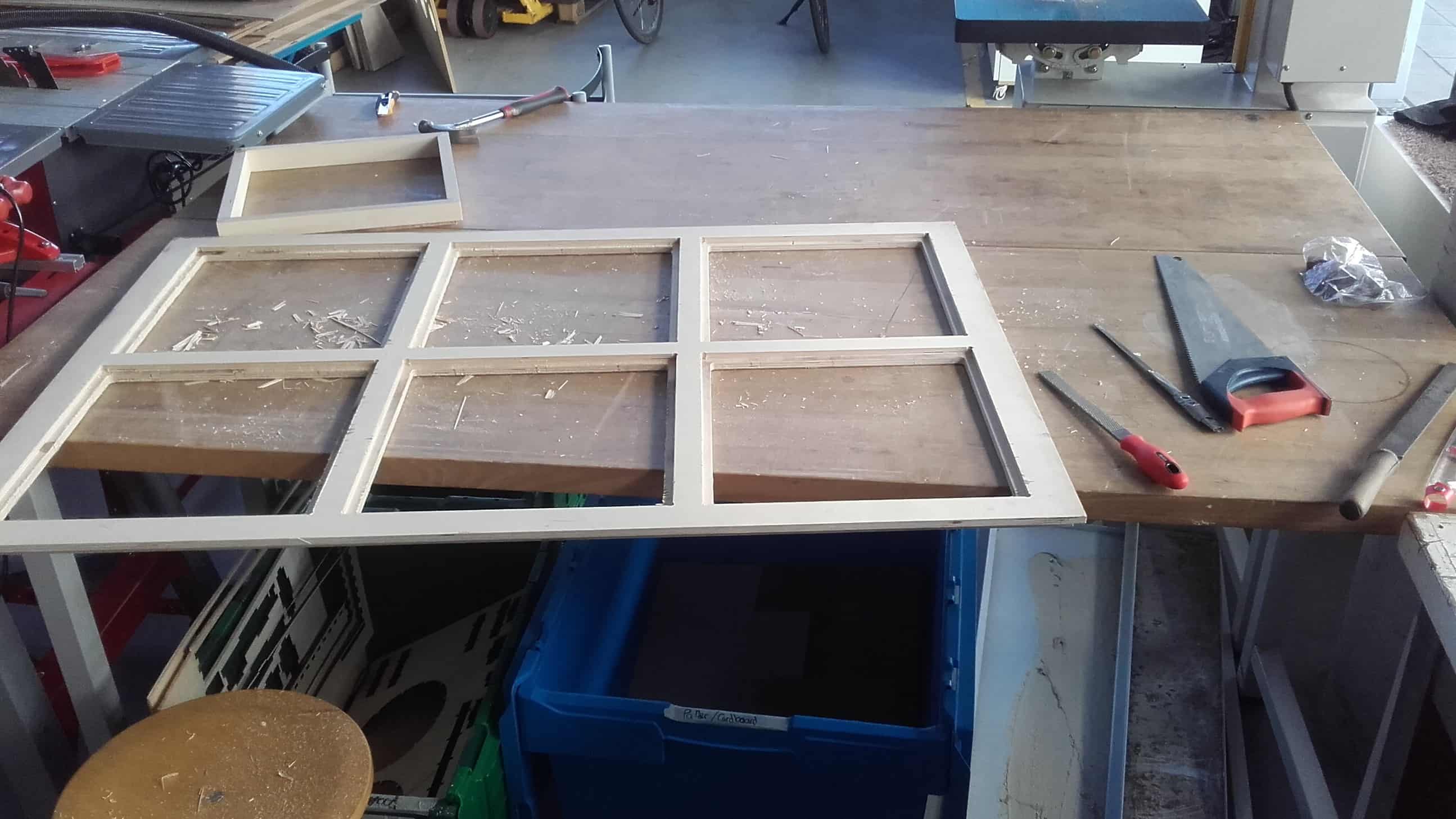
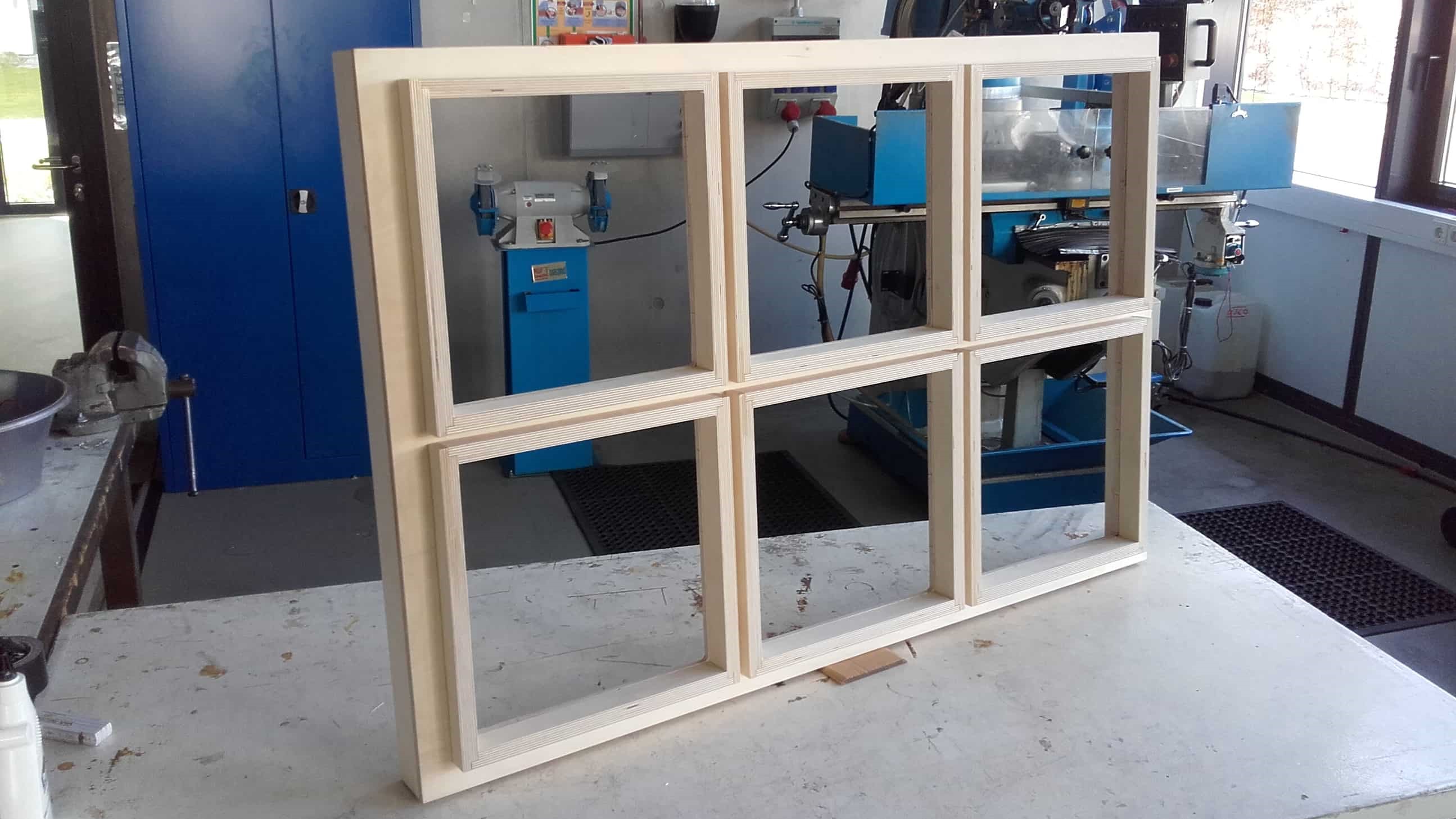
Dry Fit
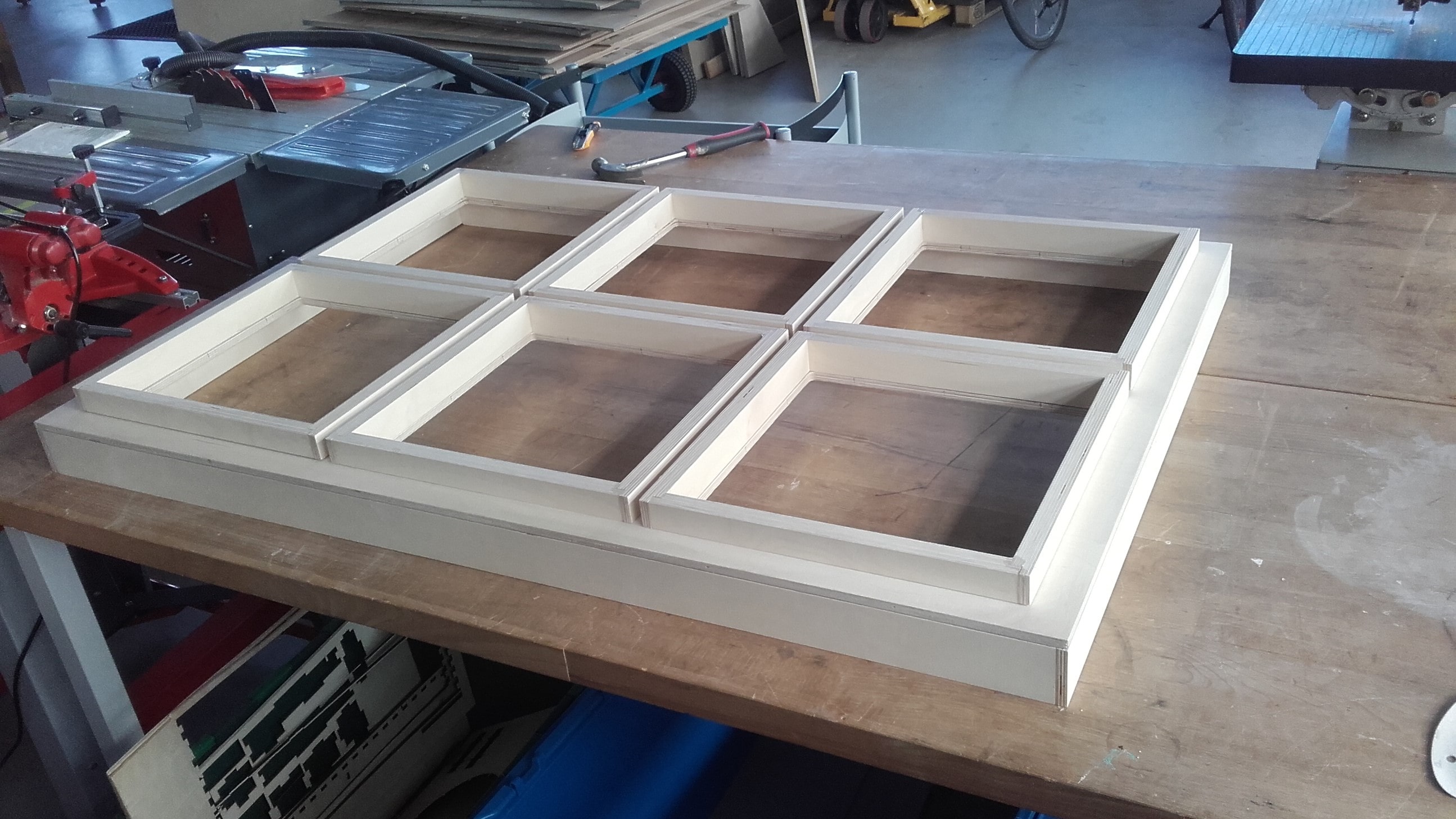
And then fit all the parts together for the first time. Overall, I was pretty pleased with how my parts overlap and coverup the chip-out from the up-cut tool. We really should get an up/down-cut one. From what I see on the internet, they make nice cuts.
Glue
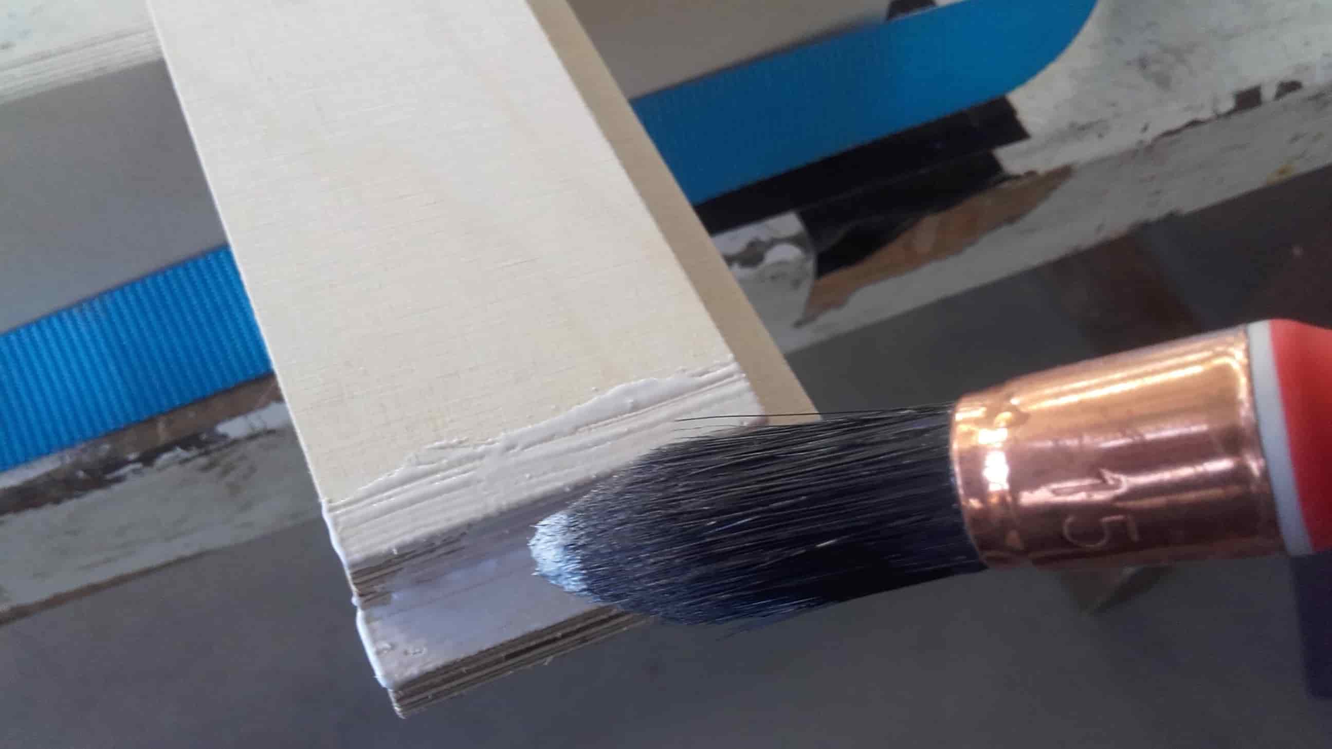
I blew off all the sawdust with compressed air and then it was time to start gluing. I carefully applied glue to both sides of every joint using a clean paintbrush.
Tie
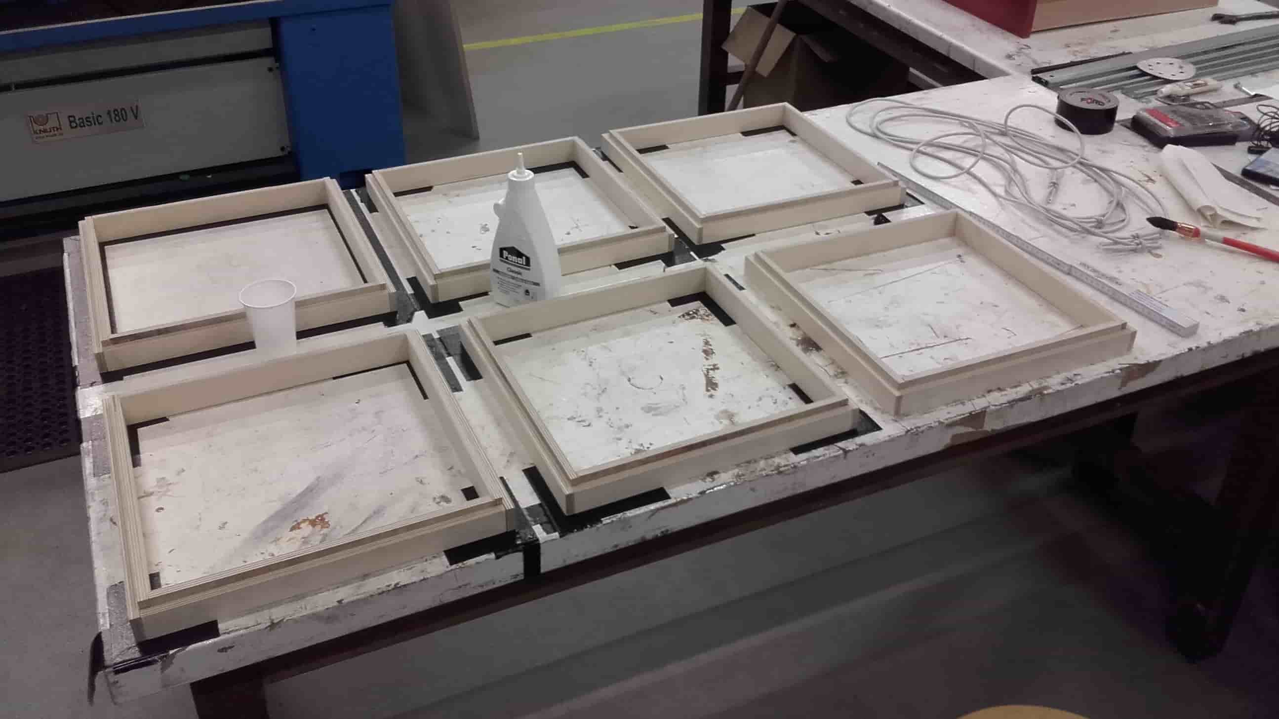
And then tied each of the small frames together using elastic bands.
More Gluing and Tying
I repeated the process using ratchet straps for the outer frame.
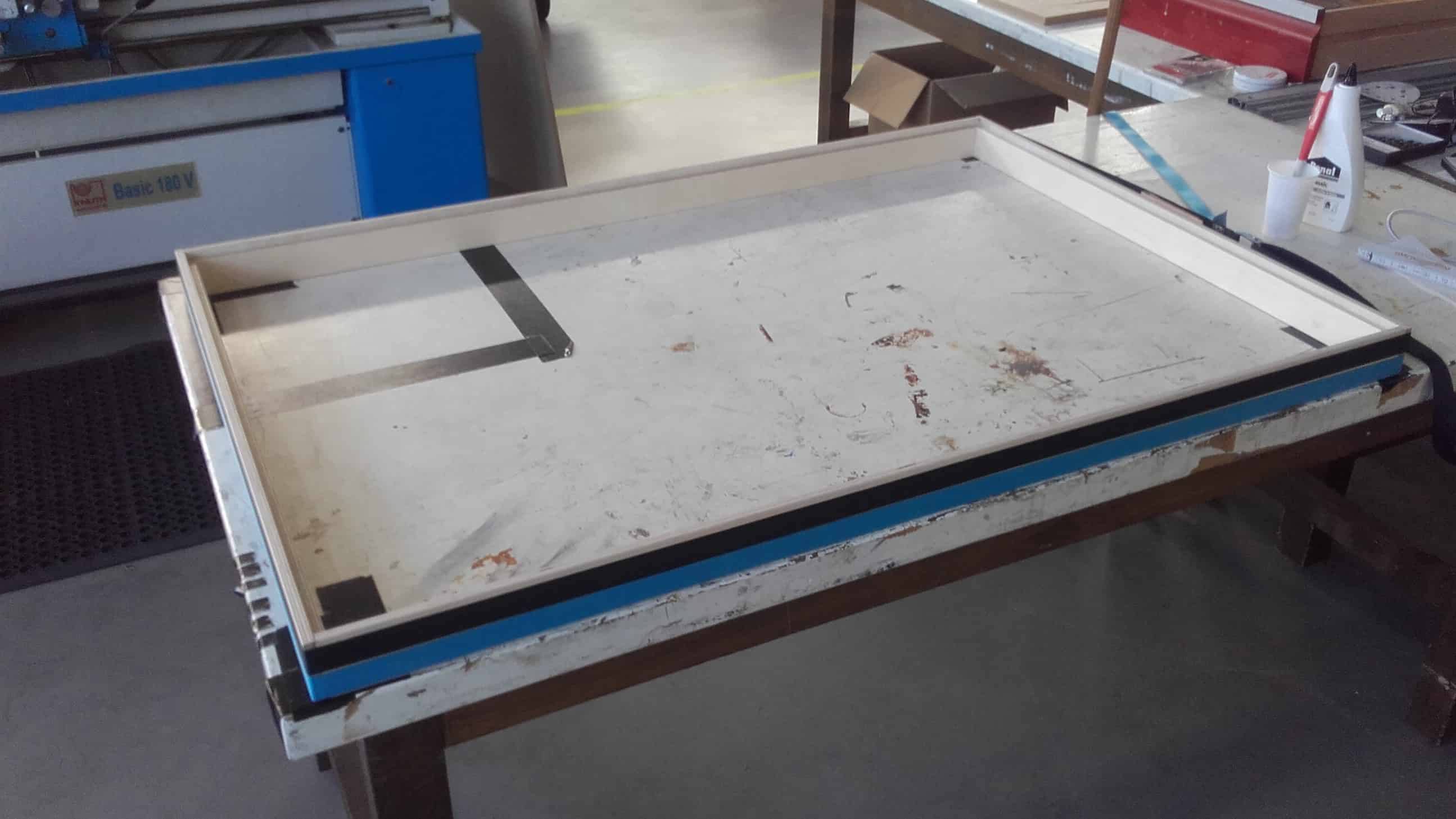
Gluing and Weighing Down
And then used various heavy things from around the shop to glue the backplate down to the frame.
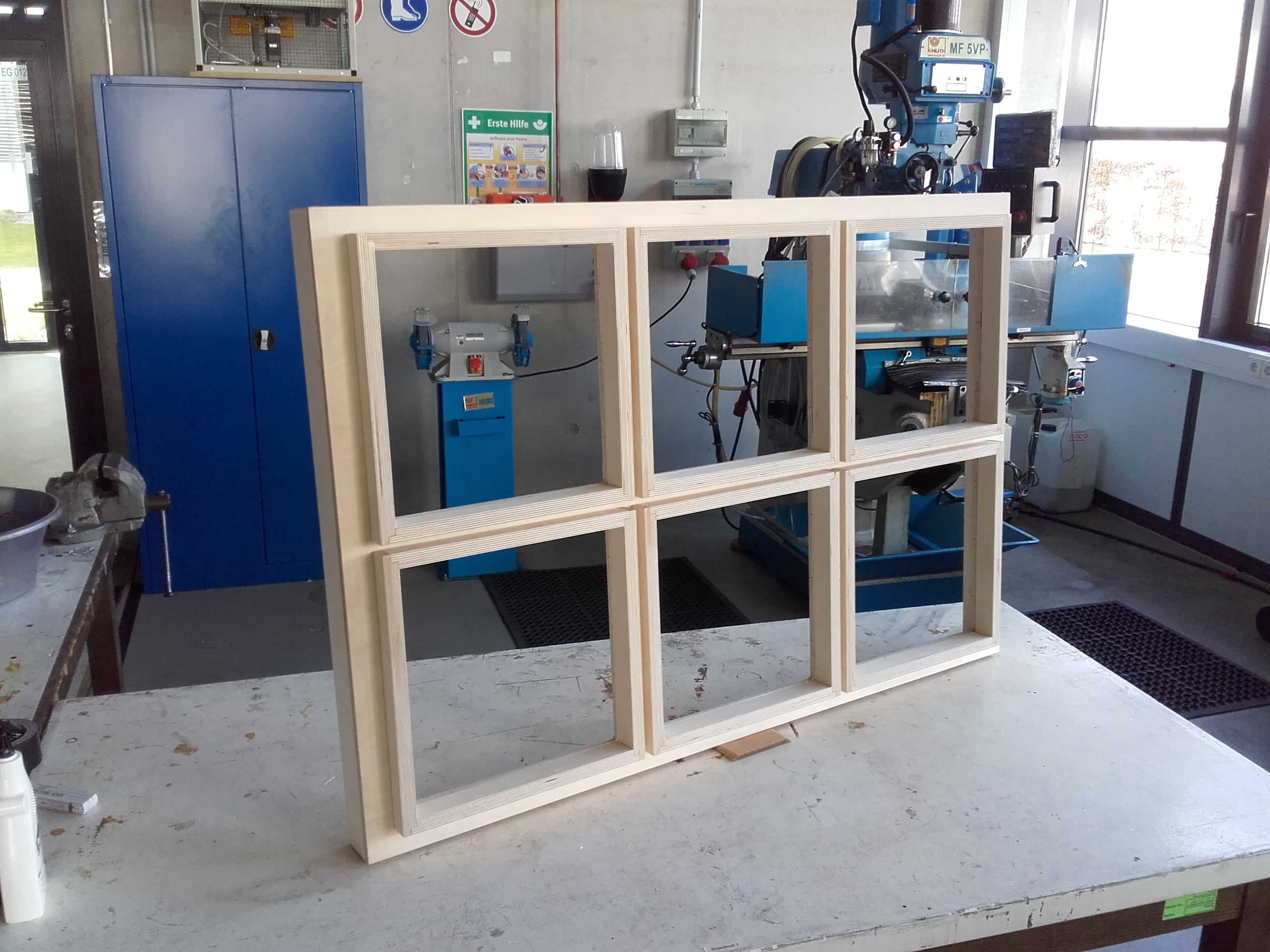
Final Result
In the end, despite the delays and struggles, the frame came out better than I expected. Time to get the electronics done so next week I can attempt to cast the topography. 😅