Computer-Aided Design
Hero Shots
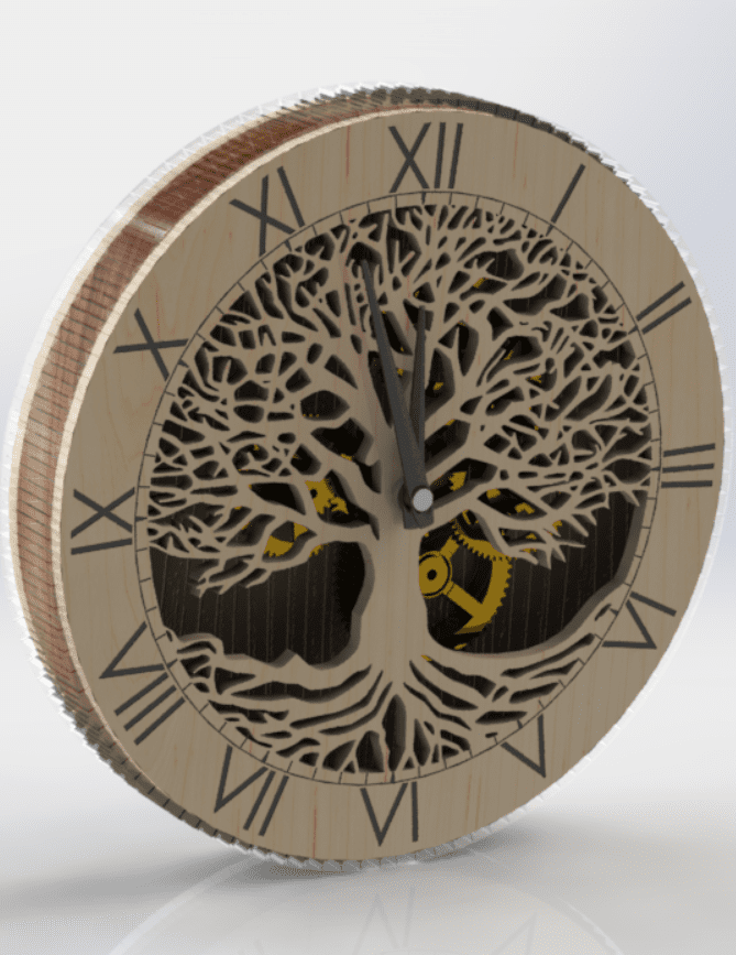
Clock Design
File Downloads From This Week
- Construx part for assignment
- Homemade corrugated cardboard texture (surface)
- Homemade corrugated cardboard texture (edge)
- Other parts can be found in Computer Controlled Cutting
Construx Assembly
Initial Reaction
This week is focused on computer-aided design in general, and parametric design in particular. I am much more comfortable with this topic, but there was also quite a bit of new information such as the distinction between rasters and vectors as well as a handful of new CAD modeling enviroment options like FreeCAD and Blender. I was also introduced to the idea of modeling using one software and simulating or rendering on other software. I don't know why it never occured to me before, but I love the idea. The assignment for this week is to create a CAD file for the final project and, of course, to document and describe the processes used in modeling with 2D and 3D software. I actually already began this last week when describing my idea for the first assignment (at least for the basic concept), but I still have quite a bit of work to do to develop the idea into something worthwhile.
After Local Workshop
The local workshop this week consisted of two parts. The first half, was focused on presenting the basic modeling capabilities of Fusion 360. The second half was about the laser cutter and designing for it since that will be the topic for next week. Although I prefer to model in SolidWorks, I am already familiar with Fusion, so the first half was a good refresher course. However, I am new to designing for laser cutting and I am excited about the possibilities. During the local workshop, I decided to focus my experimentation this week on a mini project, rather than on the final project. The idea behind the decision is to work out any kinks before applying my new skills to a project that matters more. So I decided to design a clock that could be made for next week's computer-controlled cutting assignment.
Work on Clock Project
Converting a Raster Image to a Vector
SolidWorks Test
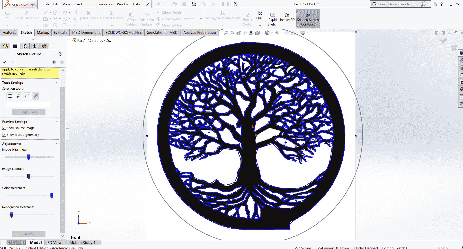
I began by finding an image that I liked for the face of the clock. The image is a raster so I knew it would need to be converted to a vector for laser cutting, but I was curious if it was sufficient to go straight to modeling, so first I tried to use the Sketch Picture tool and Autotrace to import the image to a sketch in SolidWorks. As you can see from the figure, the result was unacceptable.
Preprocessing
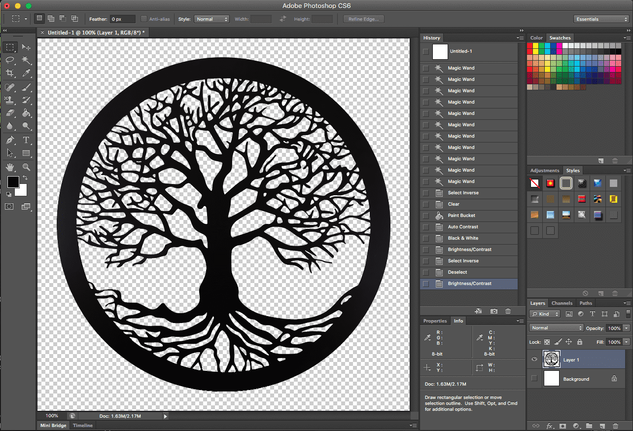
So, as I had already suspected, the image would need to be converted to a vector in order to be useful for modeling AND manufacturing. I used a combination of methods to achieve the conversion. I thought it might be easier to convert the image if it was all one color and if the background was removed, so I started with some preprocessing in Photoshop and saved the result as a png file.
Raster to Vector Conversion
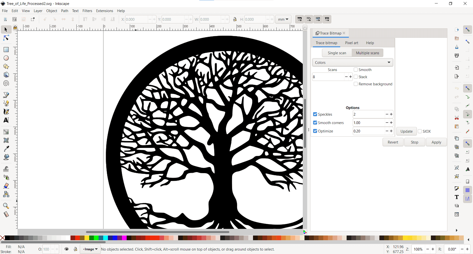
Once the image was suitable, I opened it in Inkscape. I am new to Inkscape and there is some learning curve to get over, so I "played" around with the software for about an hour and then decided to get down to the task at hand. Using this handy guide, I was able to convert the raster to a vector without any problems using the Trace Bitmap tool. I chose to differentiate by "colors" and to scan with multiple passes. I would have preferred to use an SVG file, but SolidWorks prefers to interact with DXF so that's what I chose.
DXF Import
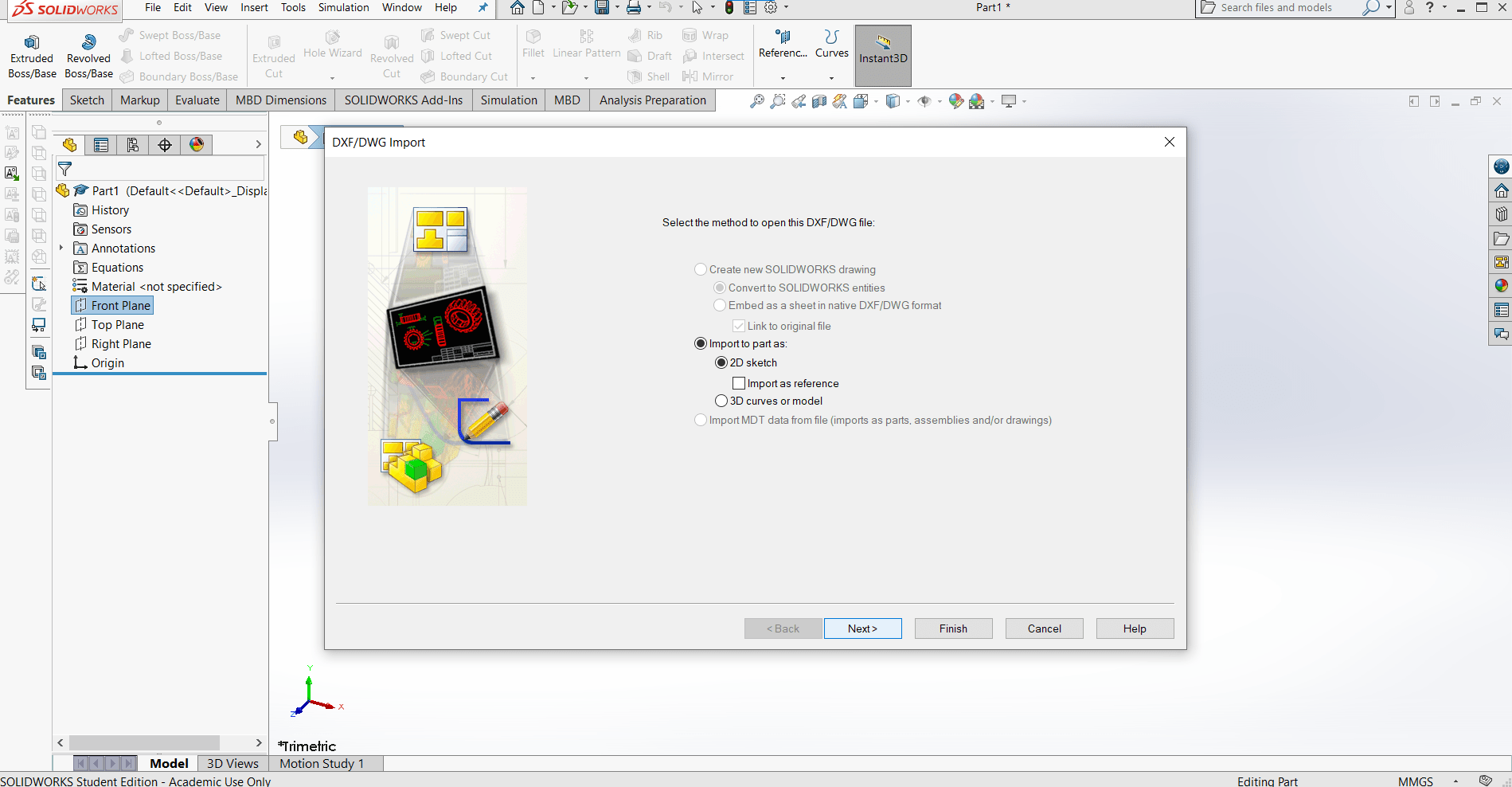
I have never tried to import a DXF into SolidWorks before so this took me a bit of trial and error, but I quickly learned how to insert it into a 2D sketch for a part. I scaled the image to my desired dimensions, and I was finally ready to begin modeling.
Modeling in SolidWorks
Generating the Part
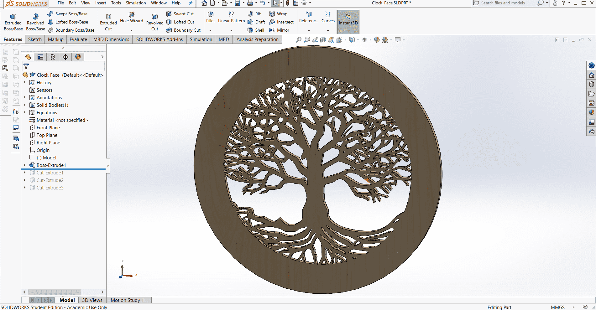
First I made a few minor adjustments to the sketch of the image such as enlarging the outer ring to be large enough for the clock numbers and then I extruded it 5mm. I believe we have 3-ply 5mm plywood with a birch veneer in the lab, so that is the material I will use for this clock.
Adding Details
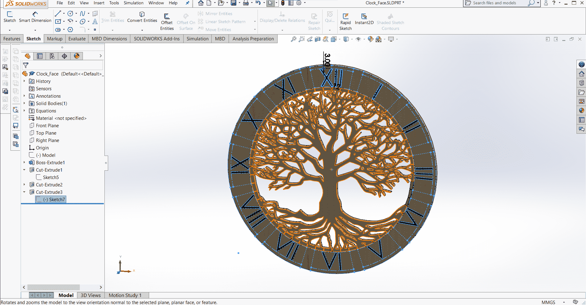
Using the Circular Sketch Pattern and Text tools in another sketch, I laid out the areas I want to engrave rather than cut. These areas include the tick-marks for each minute and the numbers. I went with Roman numerals here because I am very fancy. 😄
Side Part
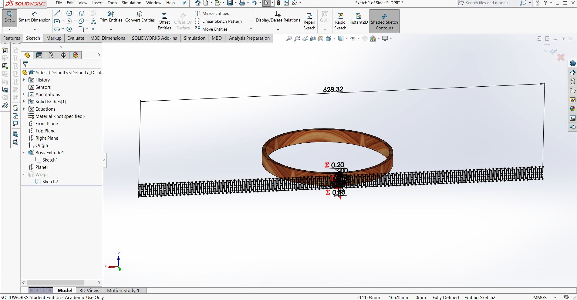
The main body was made by simply extruding a cylinder according to the desired depth of my clock. To add the cut details, I created a new reference plain and then created the sketch using the Linear Sketch Pattern tool. I used the Wrap feature with Deboss selected to remove the material from the cylinder.
Outer Acrylic Part
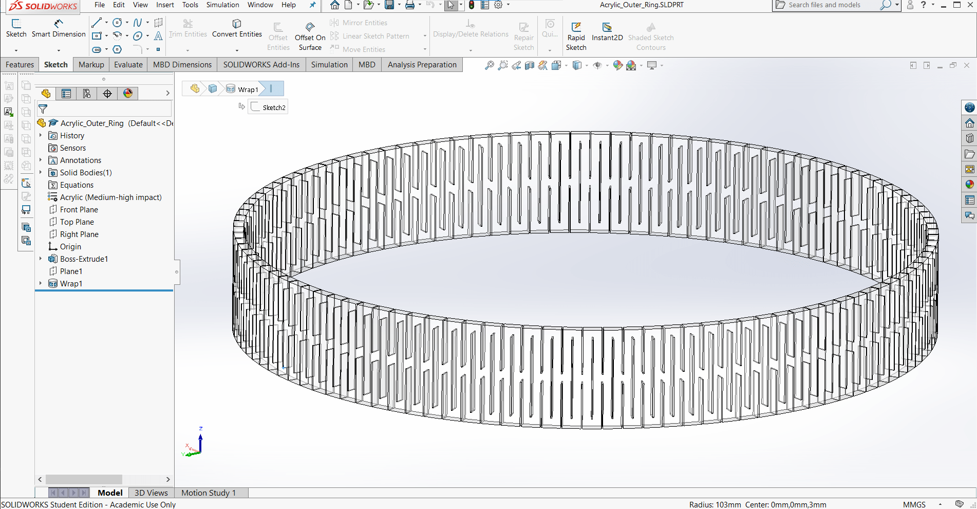
Although the fabrication will be different for this part than for the wooden one, this acrylic part that holds the others together, is made in the same way as the side part.
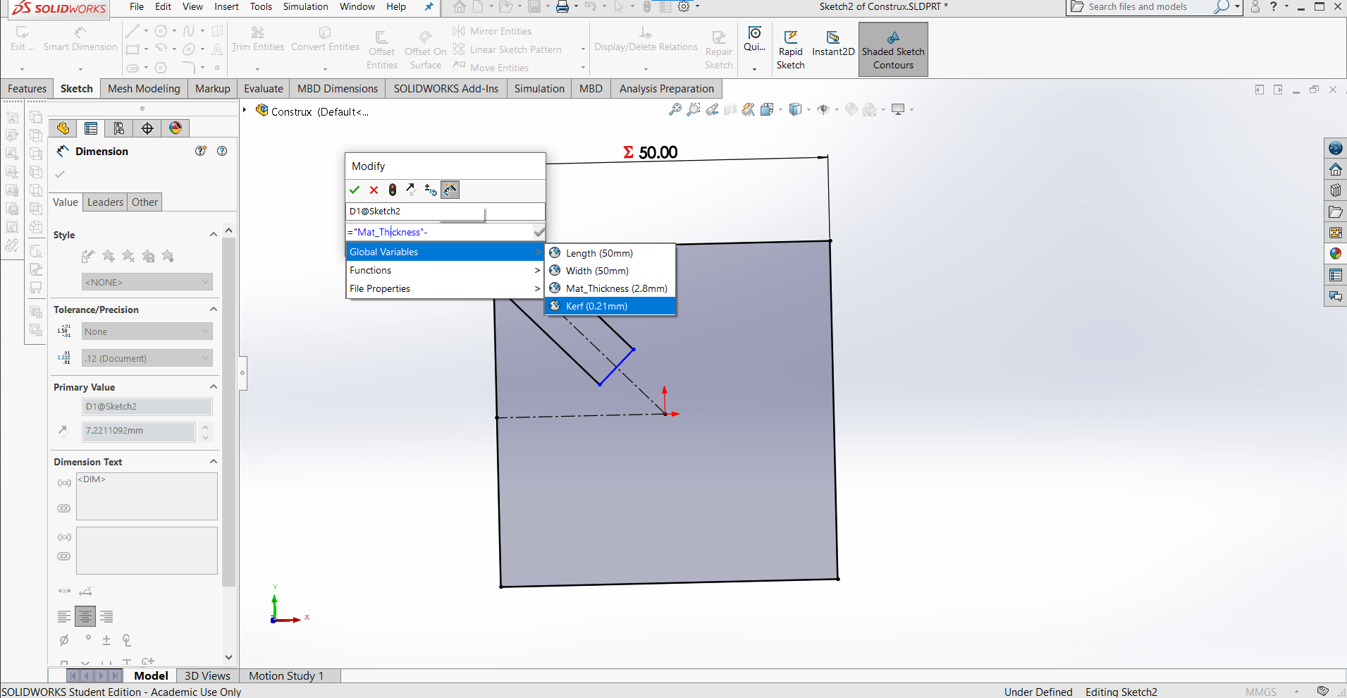
Parametric Design
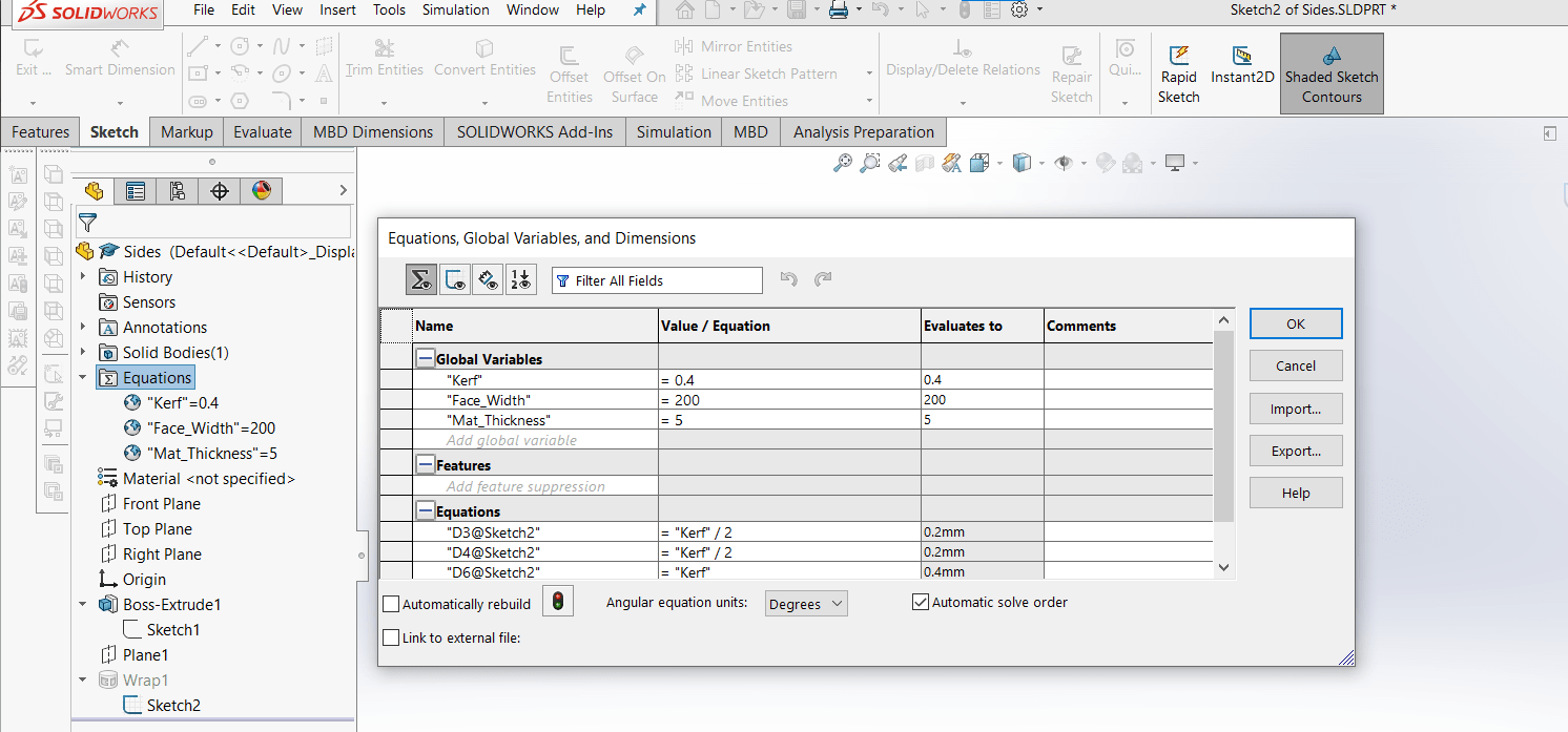
I used three global parameters for this model: "Face_Width," the overall width of the clock face; "Kerf," describes the overcutting done by the laser since it is not a zero-thickness line; and "Mat_Thickness," describing the thickness of the material. I'd like the acrylic to be less thick than the wood parts, so I may define another thickness variable later.
Clockworks
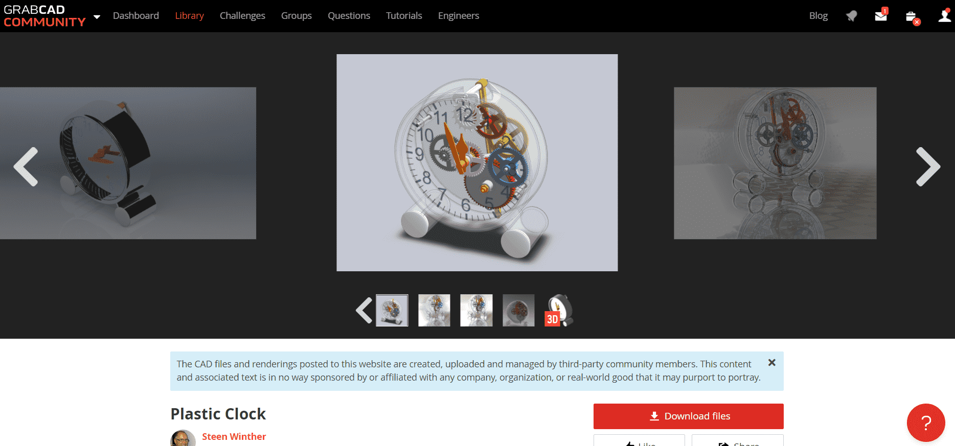
For the clockworks, I turned to grabcad. I found a model of a cool clock that had something like the gear arrangement I was envisioning and downloaded the model.
Adding and Changing Detail
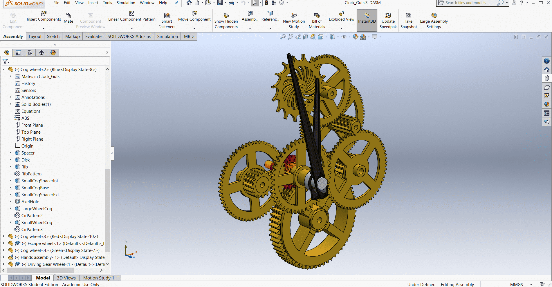
I removed the housing and the parts of the clock that would be unnecessary for battery powered motor operation rather than the spring powered, pendulum design in the original model. I also wanted the gears to be polished brass and I changed the look of the hour- and minute-hands to a sleeker design that fits my clock better.
Assembly
I work in and out of assemblies a lot while CAD modeling. The clockworks and the parts I designed are two separate assemblies since I am not sure if I will buy those parts or make them at some other time...perhaps for another FabAcademy weekly assignment.
Redoing the Assignment
Back In Solidworks
New Sketch
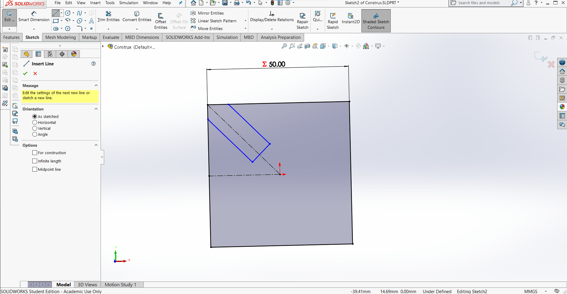
I began with a new sketch in SolidWorks. I made the basic square shape and the slot using the Line tool.
Adding Relations
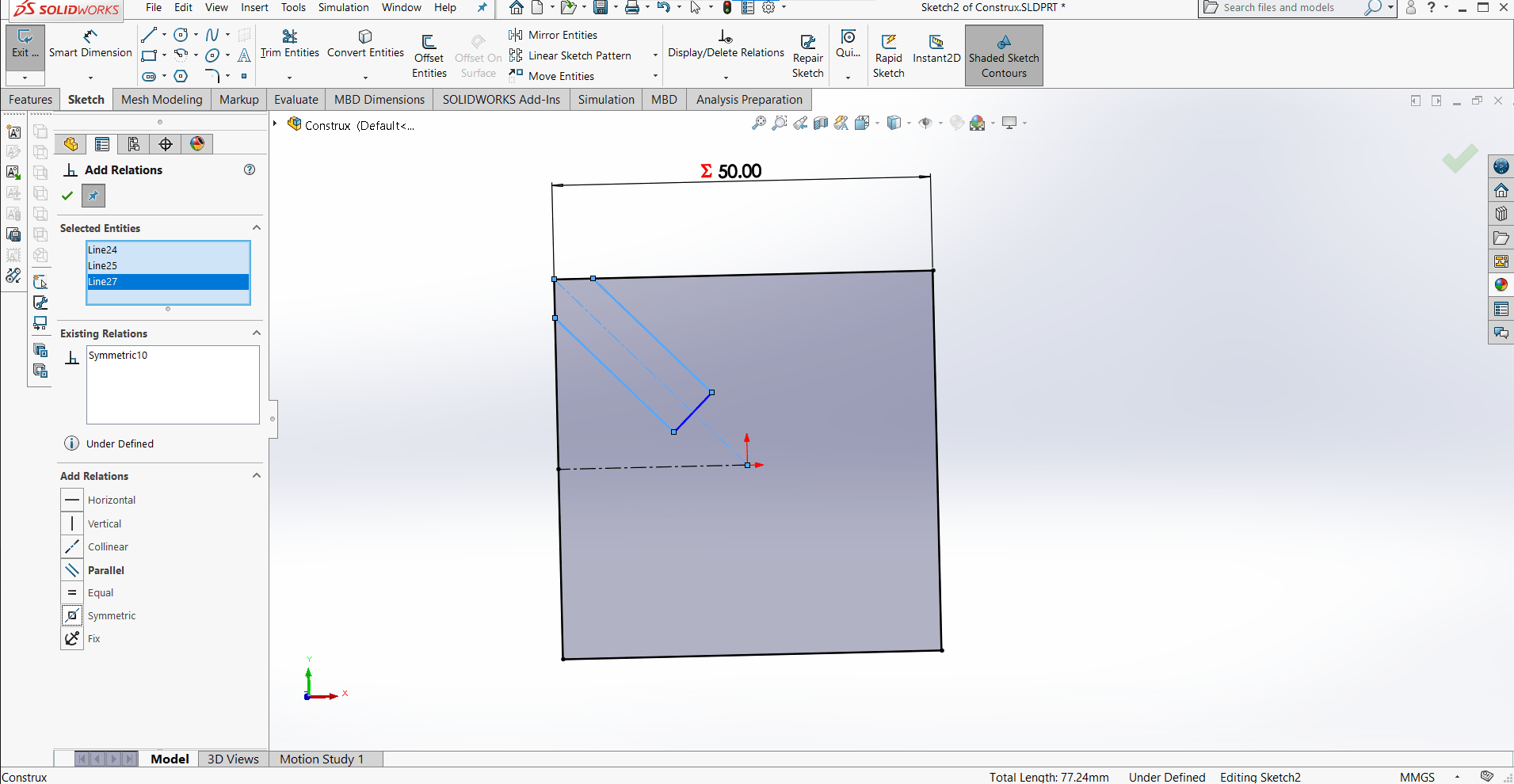
I added relations to keep everything centered on the origin to make it easier to mirror and mate later.
Parametric Design
And I kept everything parametric so the whole model will update if a single variable, such as the kerf, is changed.
Fully Defined
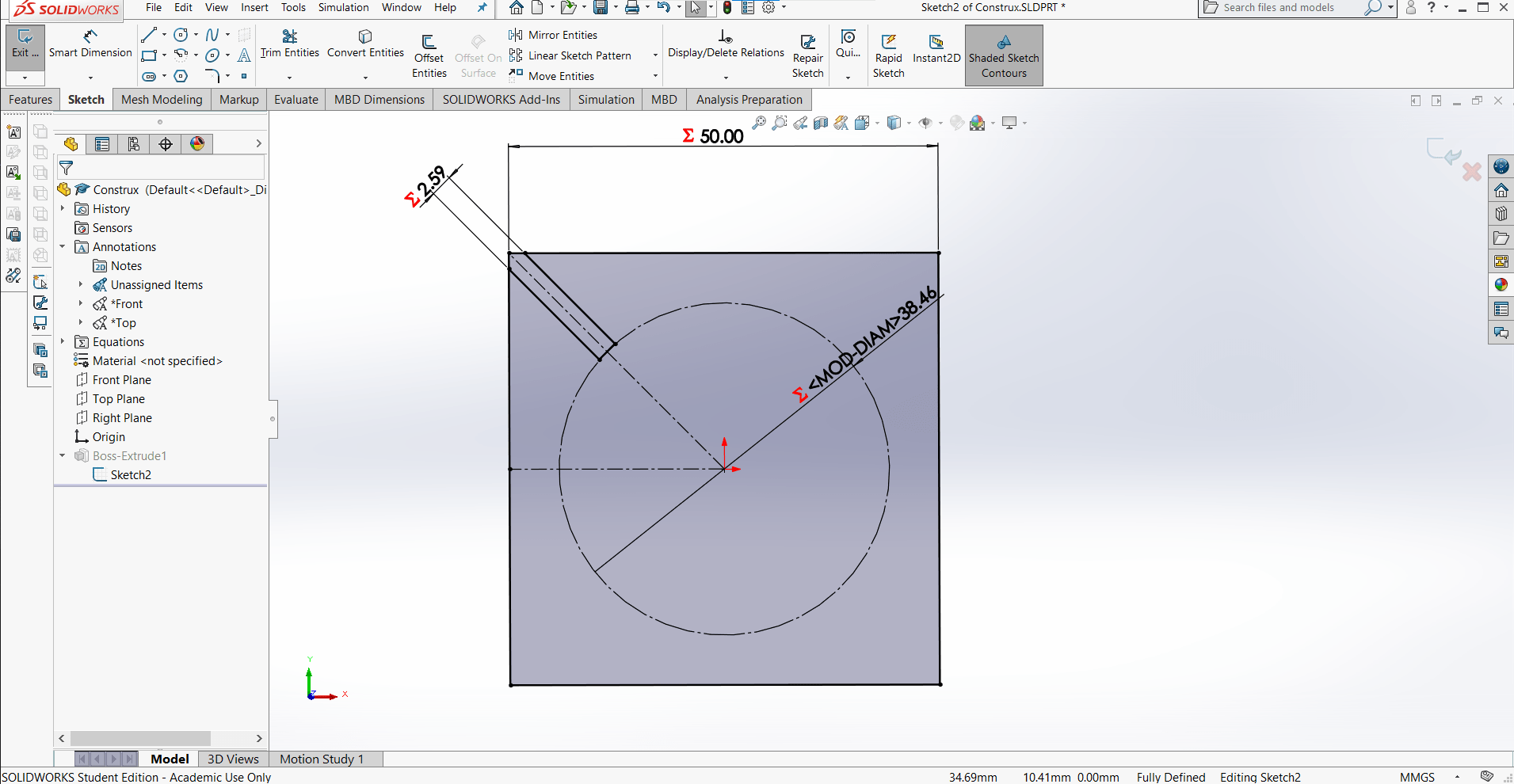
I added the dimensions for the slot...
Circular Pattern
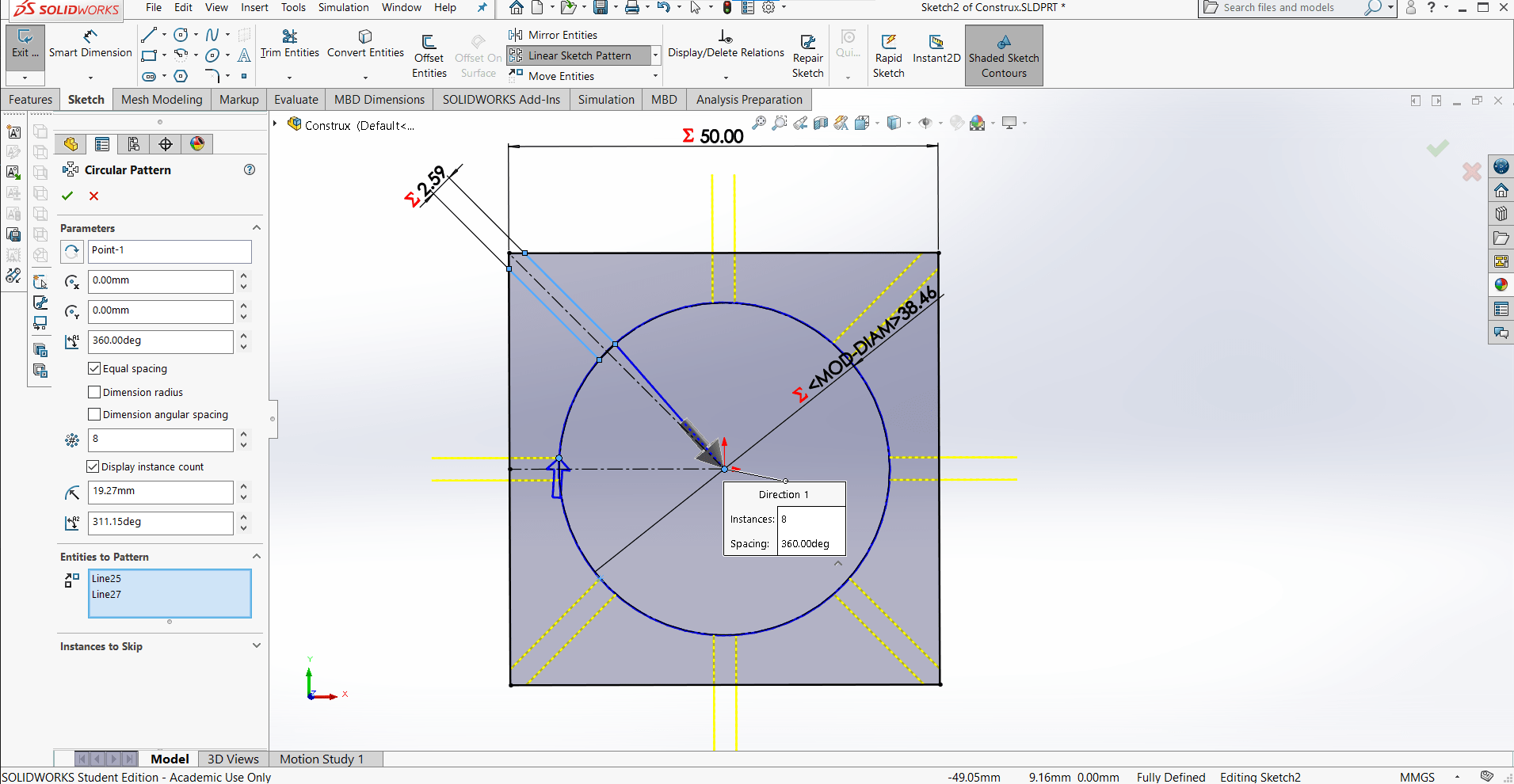
...and then created a Circular Sketch Pattern so the slot would be repeated on every edge and corner of the square shape.
Trimming
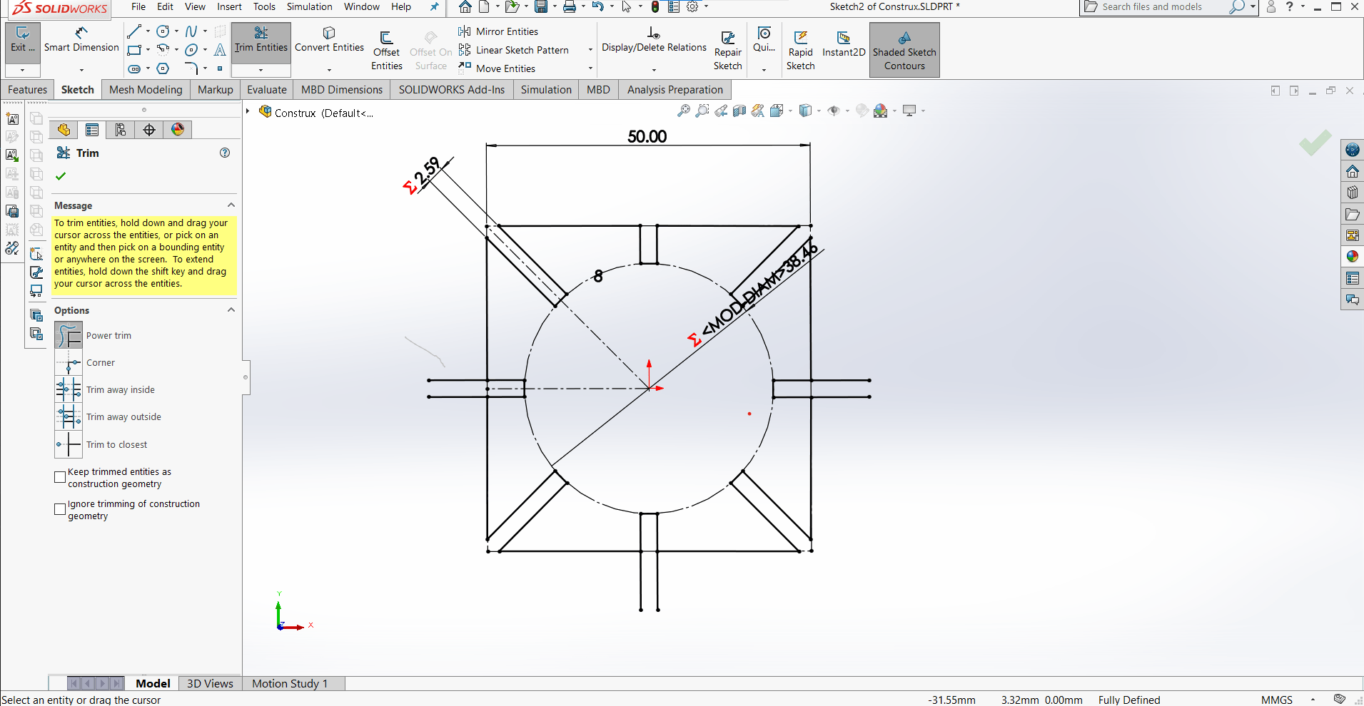
Then I trimmed off the bits I didn't need with the Trim Entities tool...
Boss Extrude
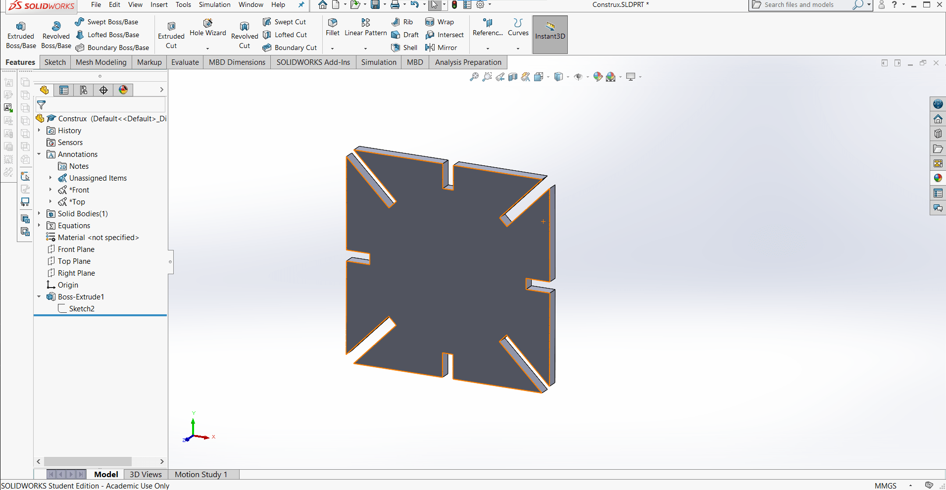
...and extruded the shape into the third dimension with the Boss Extrude feature. Instead of chamfers, this time I decided to try out fillets.
Fillets
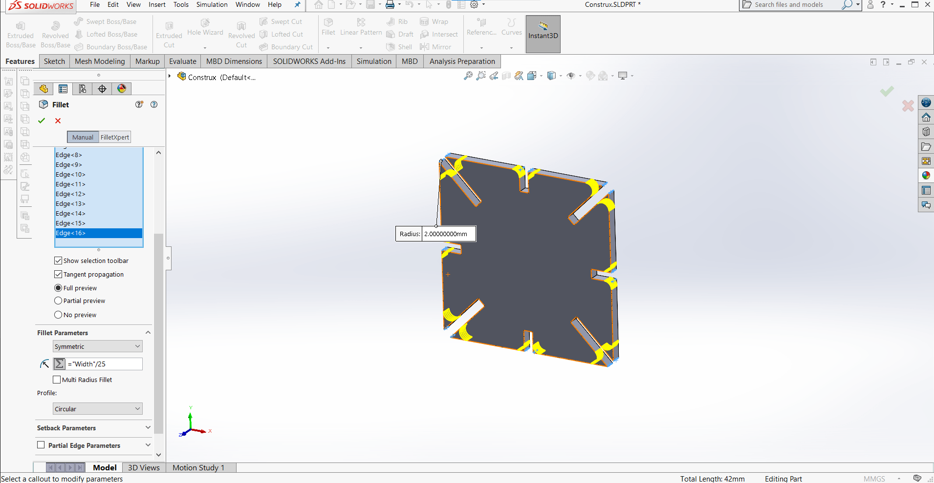
I could have created them in the sketch, but SoldiWorks doesn't allow you to link a sketch fillet to a global variable, so I decided to use the Fillet feature on the extruded part so I could keep the fillets parametric as well.
Assembly from Part
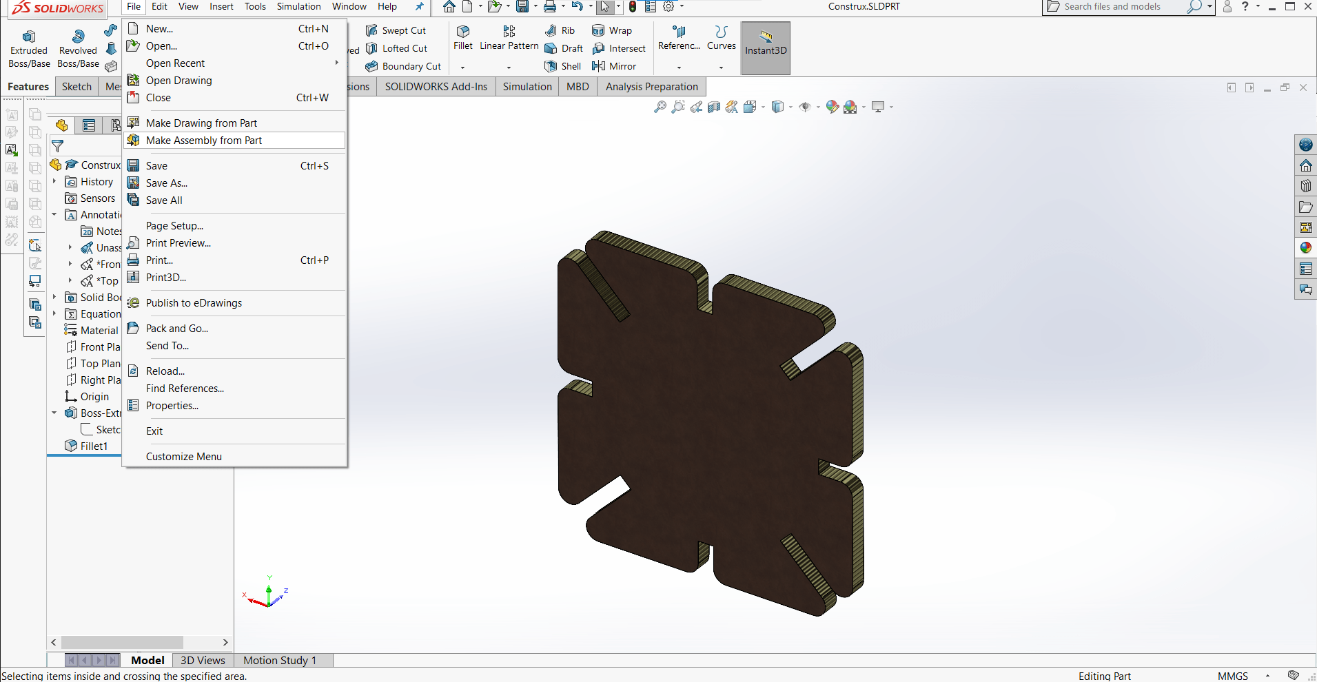
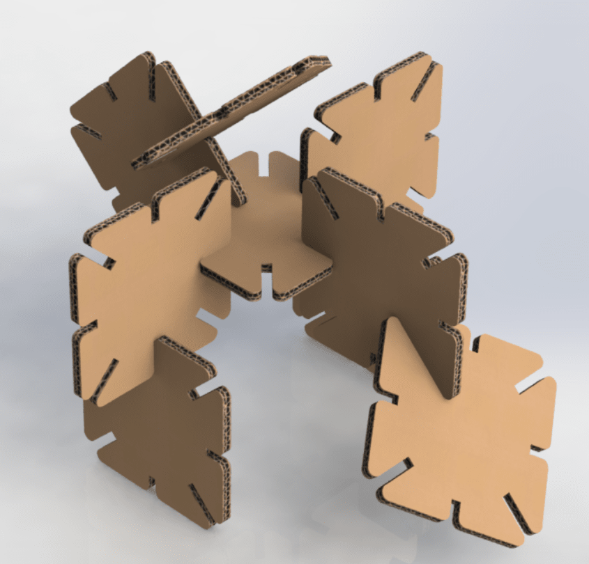
Once the part was finished, I wanted to show how it would connect, so I made an Assembly from Part.
Spawning Duplicates
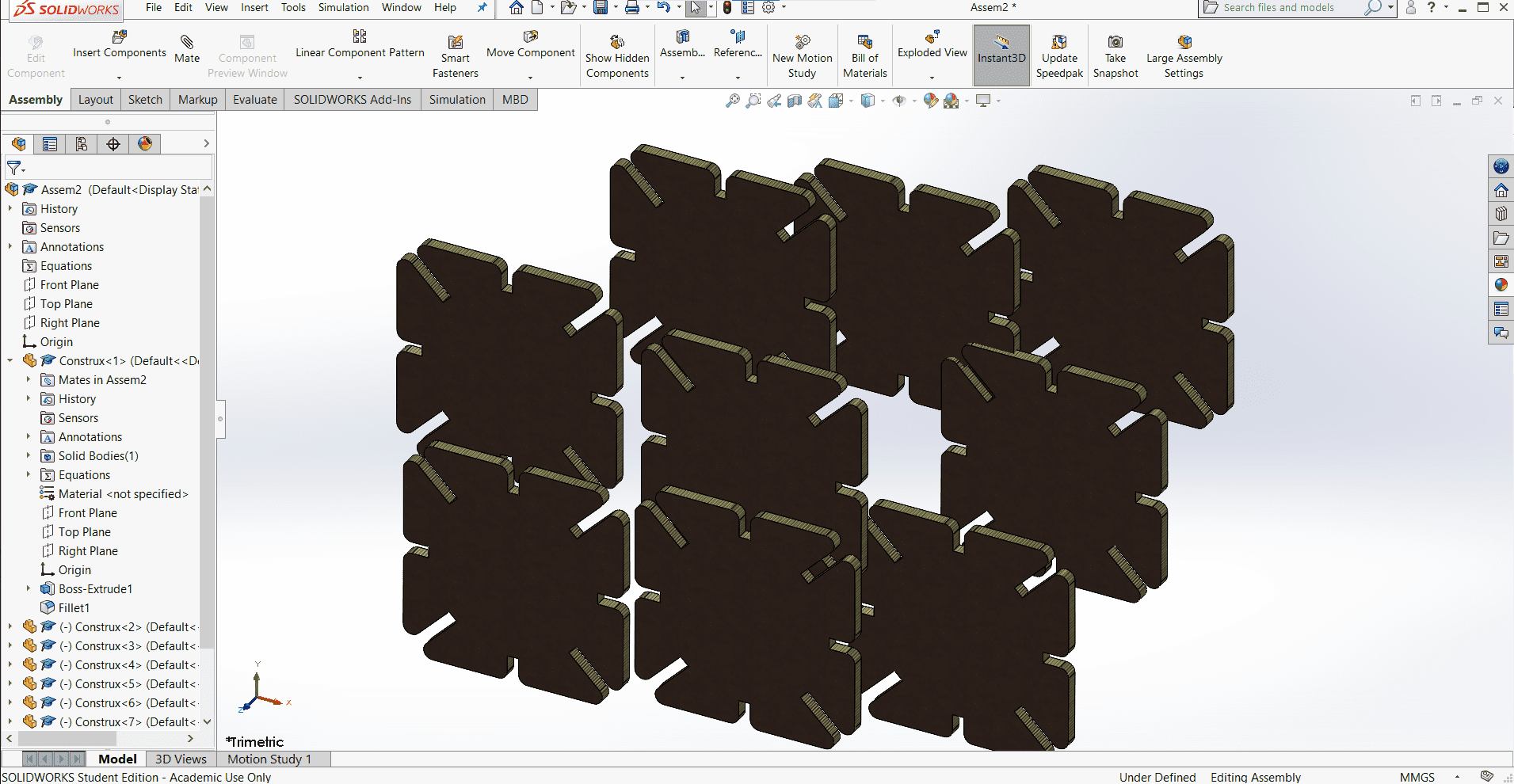
In the new assembly, I created a bunch of duplicates using Ctrl+Click...
Mating
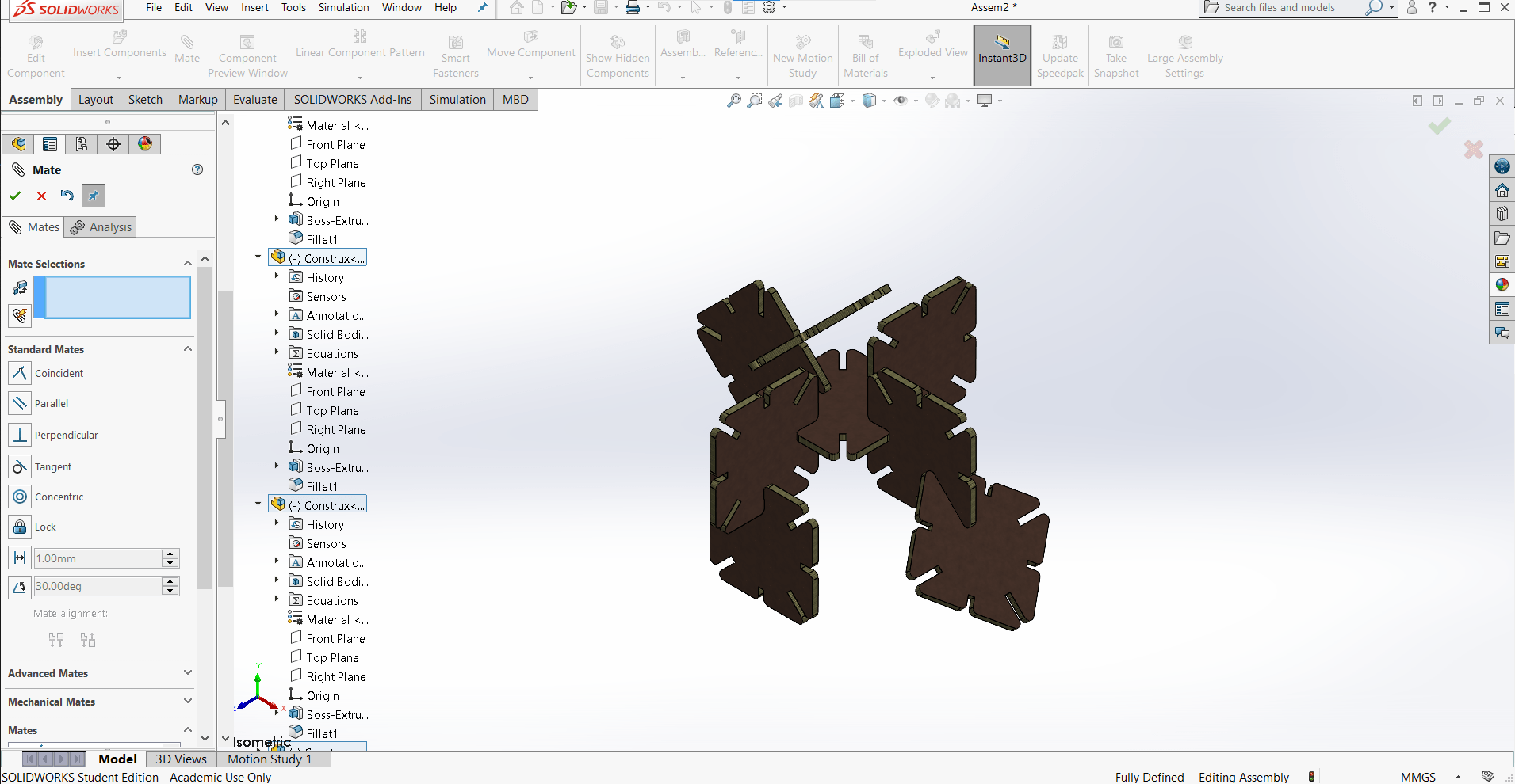
...and then started mating them together using their primary planes whenever possible.
Appearances
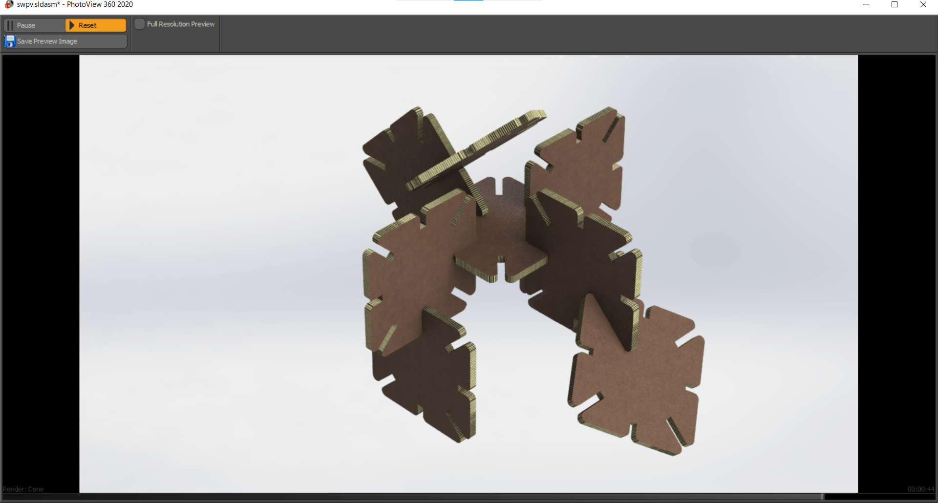
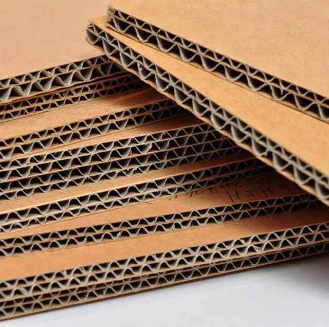
For a final render, I wanted the part to look like corrugated cardboard since that is the material I intend to cut it from, but SolidWorks doesn't have a texture for cardboard.
New Appearances
So I set out to make my own. I bagan by finding some images of the cardboard I wanted and then cleaned them up in Photoshop. It is difficult to convert jpgs (the image I had) to ..P2M files (the default filetype SolidWorks uses for appearances and the only type allowed for renders in Photoview 360) so I came up with a hack to be able to save the new appearances. SolidWorks allows you to use a jpg as an appearance in an assembly file (not a render), and it also allows you to save your appearances when saving an assembly...and one of the file type options during saving is a .P2M file. So, it is possible to use SolidWorks as the tool to get around their own silly filetypes. Just in case it they are useful to anybody else, I have included the appearance files that I made. They can now simply be added to the directory of materials for SolidWorks. Program Files\SOLIDWORKS Corp\SOLIDWORKS\data\graphics\Materials...
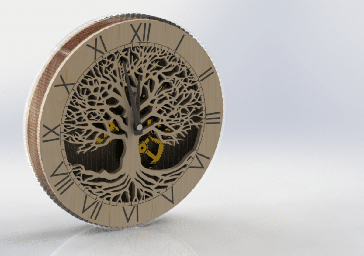
Finished Product
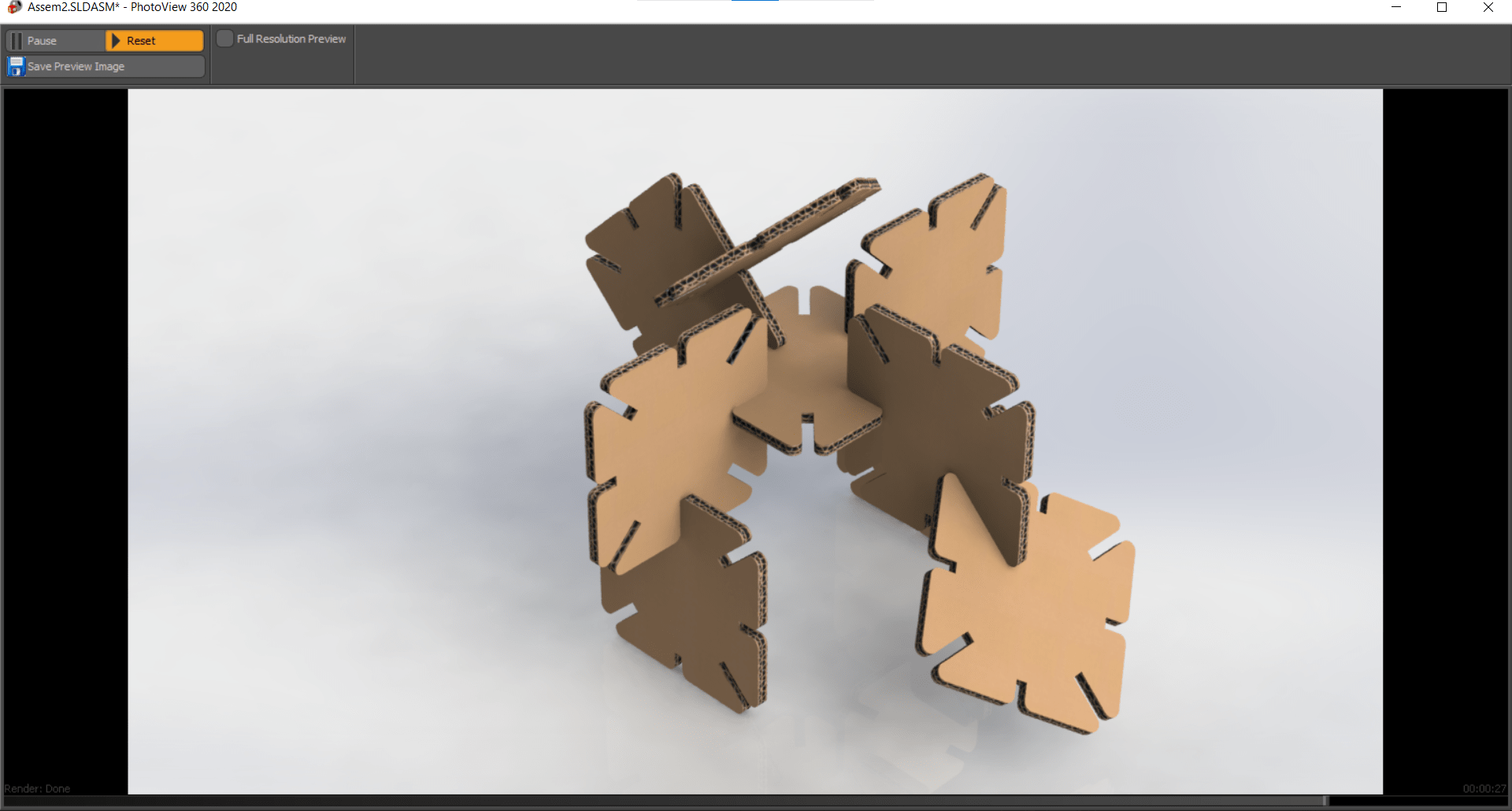
Finally finished, here is the render of the assmebly with the new cardboard appearances.