Interface and Application Programming
Hero Shots
Click Here for Our Group Assignment
My Interface
Initial Reaction
This week is all about interfaces and applications...or at least that's what I think it's all about. Once again, I was pretty lost during the lecture. Neil is impressively knowledgeable; I just have no experience with all the acronyms, and these lectures are starting to feel like alphabet practice. The assignment for this week sounds easy enough; we have to create an interface to control an input or output device that we made, but I know from experience with these projects that they are rarely as easy as they sound. Our group assignment this week is to experiment with as many interface building tools as possible. As usual, that's not very clear. I'll definitely be going for the low hanging fruit once again for this topic.
After Local Workshop
Feeling good after the local workshop. Marcello spent a few hours introducing us to the Anaconda Navigator, JupyterLab and Tkintwerkthingy. We learned the basics of how to make simple widgets like buttons and how to create entries that require inputs as well. Then he showed us how we could combine the widgets into more complicated widgets. We finished the class with him showing us how to use our widgets to control a microcontroller.
Making a GUI
Basic Widgets
TK Library
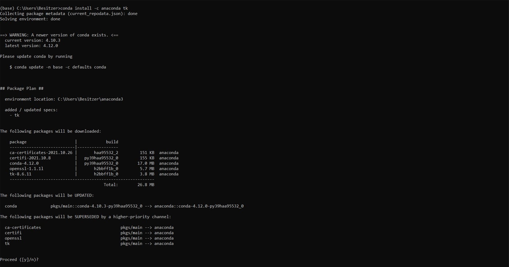
I started by downloading the Anaconda Navigator and Prompt and then I used the prompt to install the tk library with the conda install -c anaconda tk command.
JupyterLab
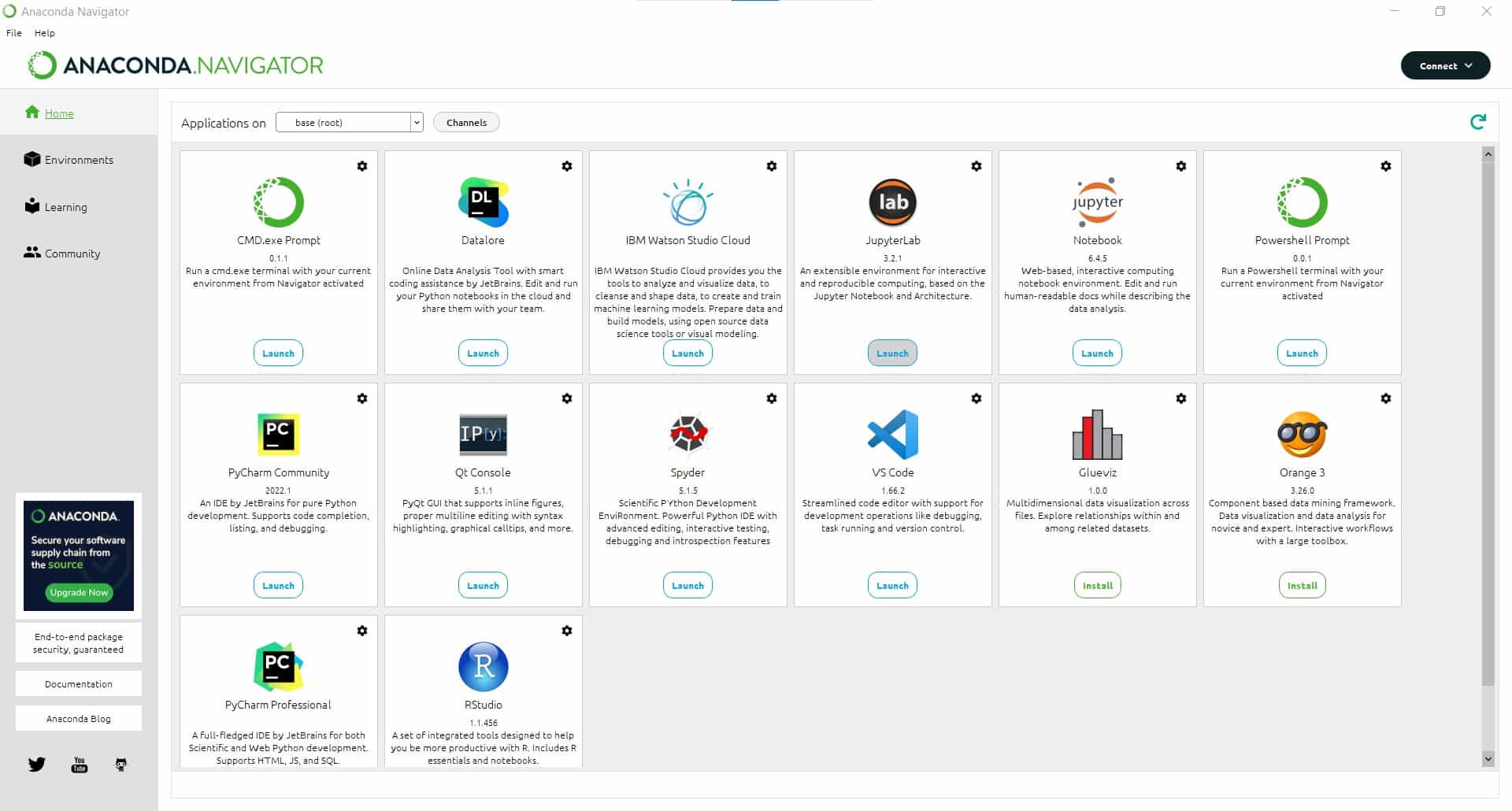
Next I opened up JupyterLab from the Anaconda Navigator and started experimenting.
Basic Widgets
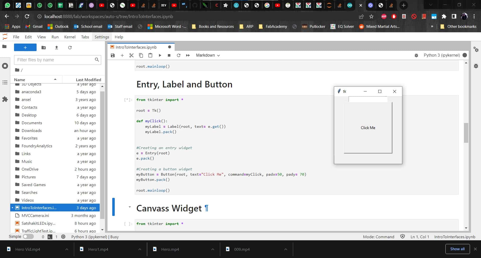
Using Marcello's notes from the local workshop as a reference, I was able to recreate the basic widgets we made. I was able to get most of them working without any real difficulty.
Controlling an Arduino Uno
Physical Pixel
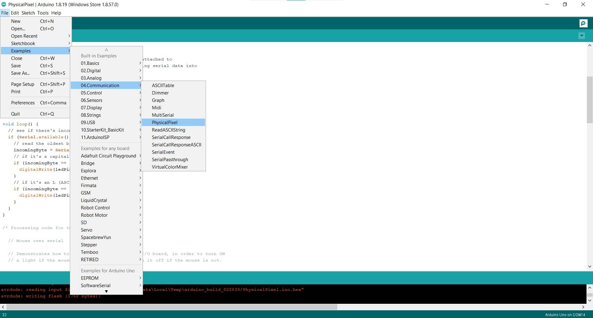
For the widget to control a board, I got into the Arduino IDE and opened up the Physical Pixel code from the Communication examples.
Test with Serial Monitor
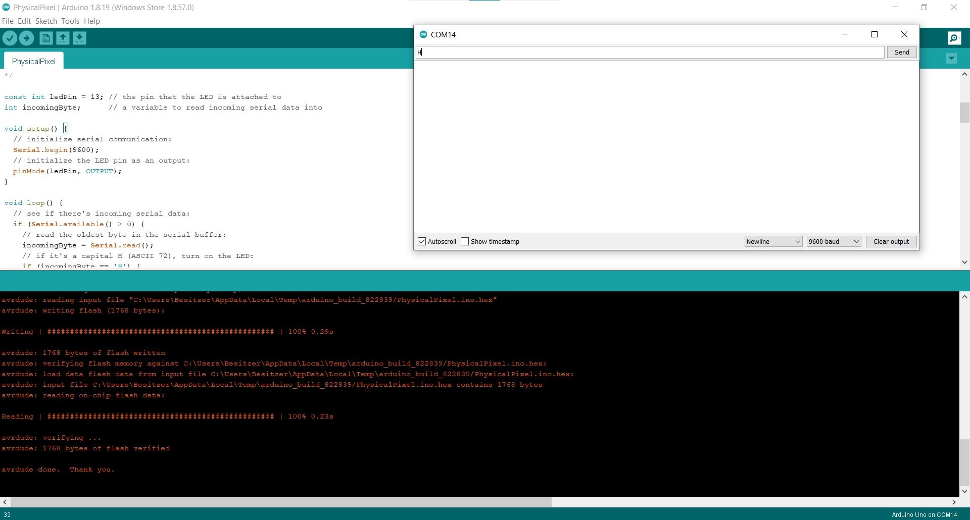
Before trying to control the board with my new little GUI, I wanted to double check that everything was working on my Uno.
So Far, So Good
I uploaded the program and tested it using the serial monitor. When I put in "H", the LED lit up, and it turned back off with "L". Good News.
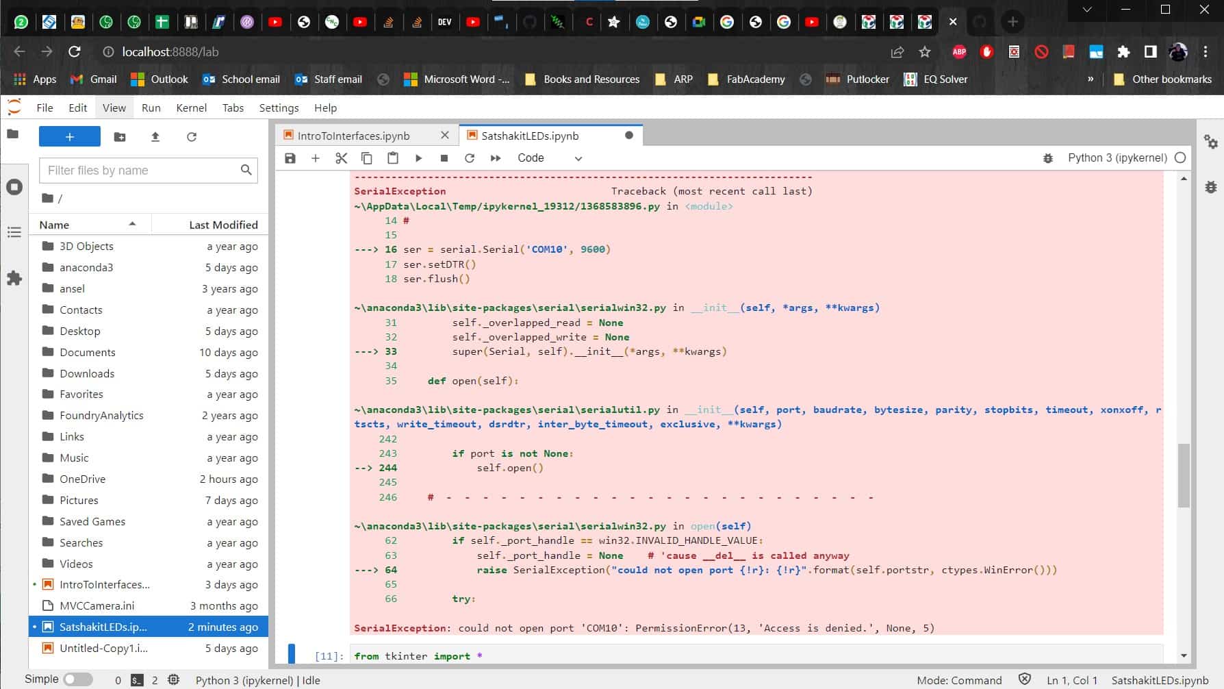
Error
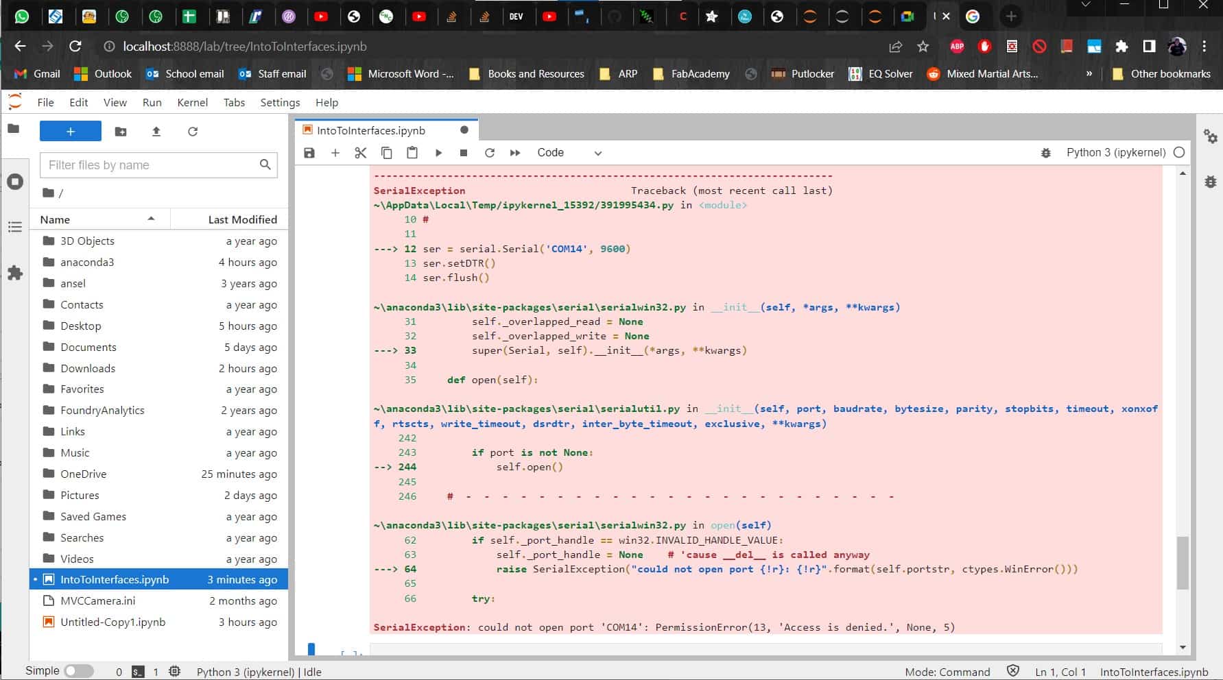
Unfortunately I kept getting an error when I tried to run the GUI code to control it.
Solution, Sort of
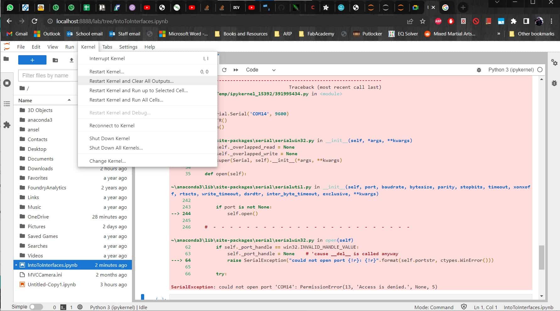
After consulting with the local experts in the lab, I discovered that I had to restart the kernel in the GUI, re-upload the code to the Arduino, and then run the GUI code again.
Better Solution
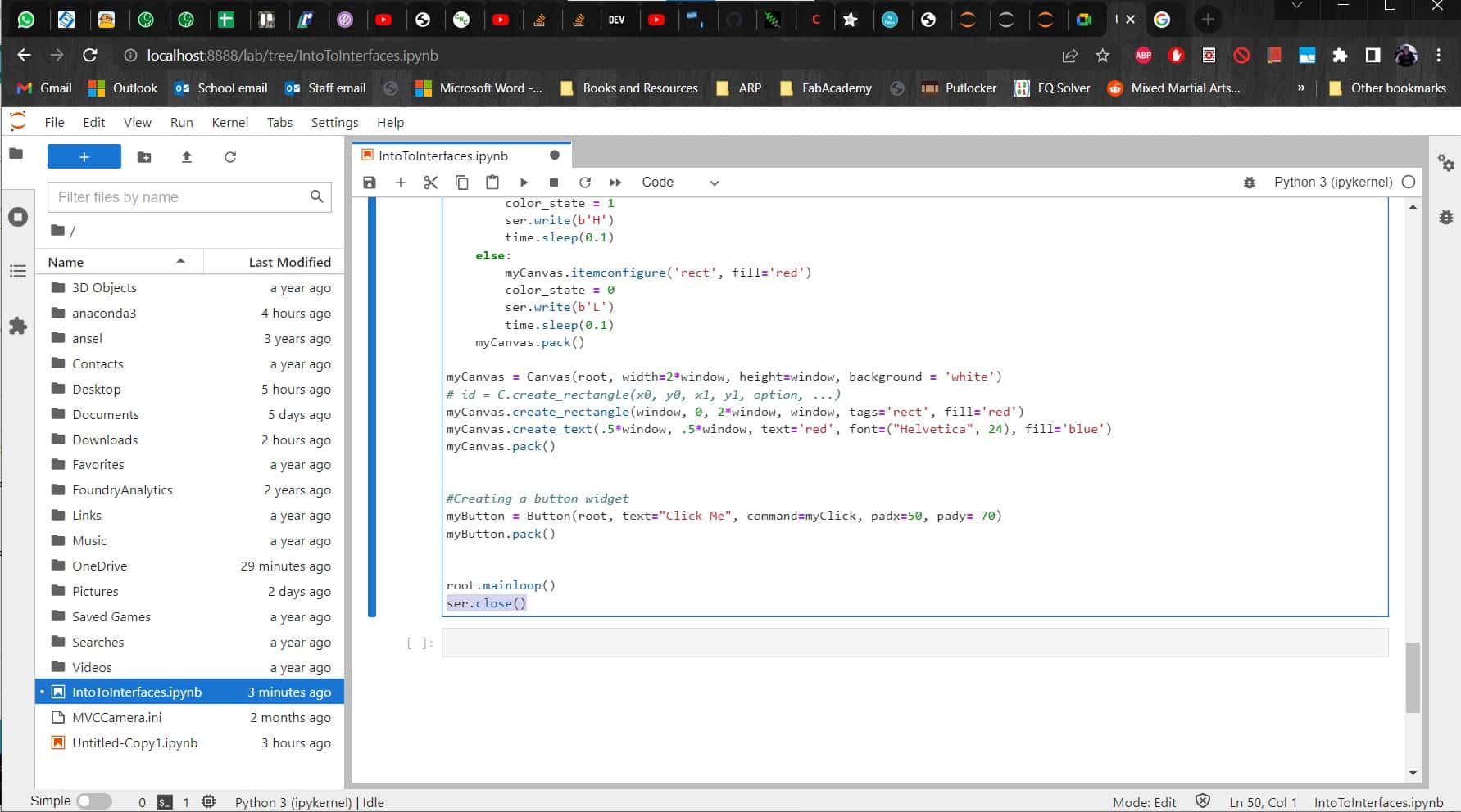
I could have accepted having to do it once, but it wanted me to repeat the process every time I ran it again. Tedious. Fortunately Leen taught me about a very useful command to close the serial port after the loop. ser.close()
Success
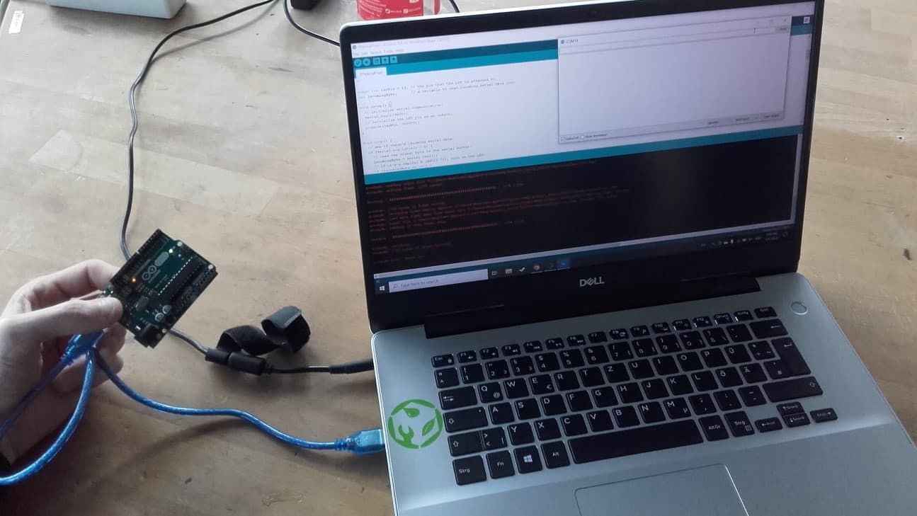
Finally, the programs were working correctly and I could activate and deactivate the LED on the Arduino using the buttons in the GUI on my laptop. Very satisfying.
Controlling the Satshakit
Labels
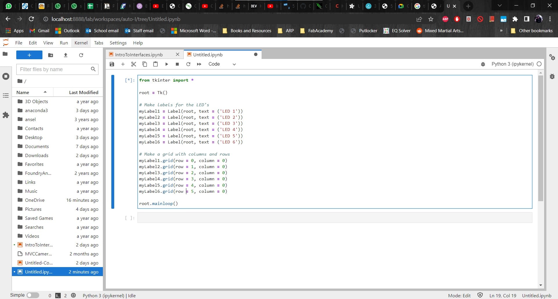
It was time to start working on the code for controlling my Satshakit. I started by making labels and adding them to a grid.
Stealing From Examples
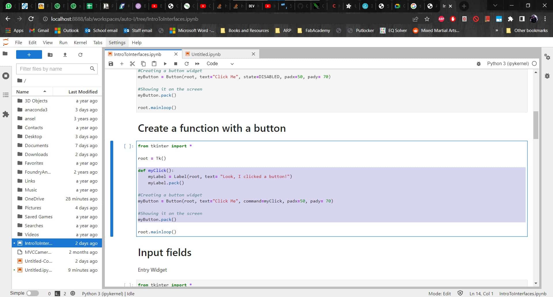
I also copy and pasted some of the examples from Marcello for things like buttons and clicking functions.
Another Error
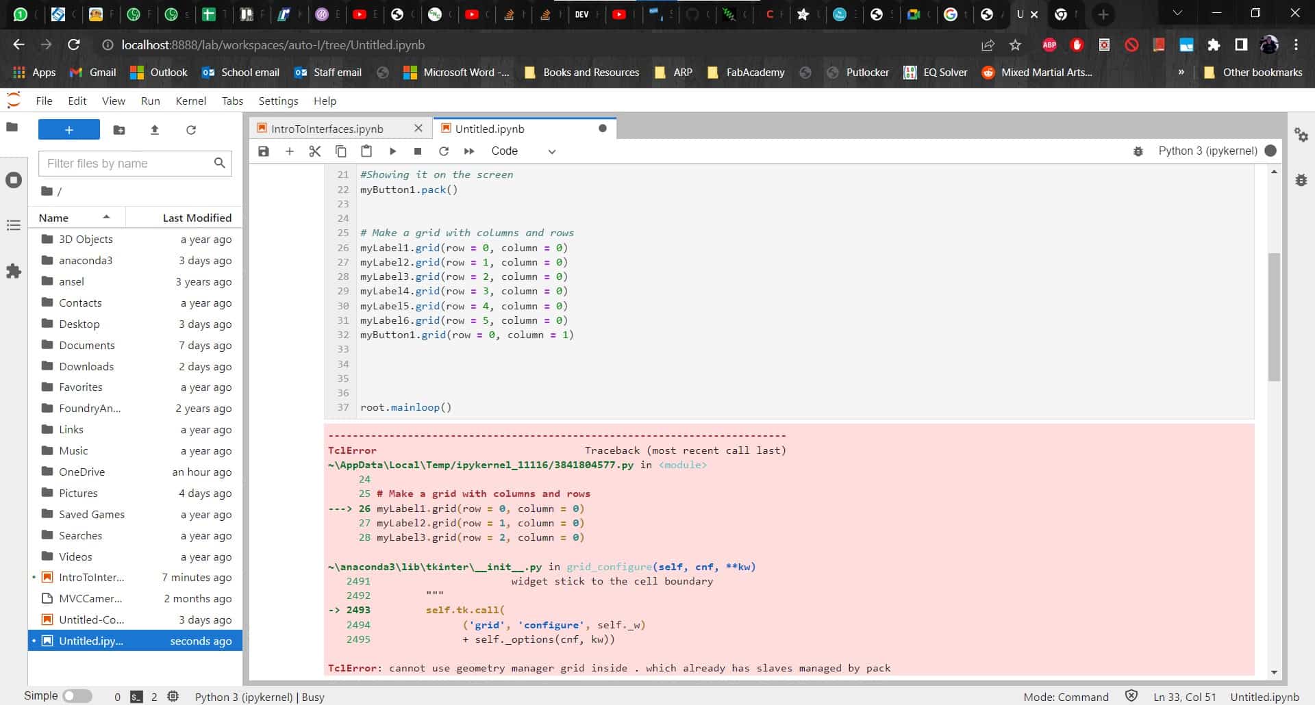
I tried to run it just to make sure that all the easy stuff was working, but I encountered another error right away. After some consulting on StackOverflow, I discovered that you cannot use .pack() with a grid system.
No More .pack()
...So I decided to get rid of the .pack() and to just use the grid. Thankfully that worked.
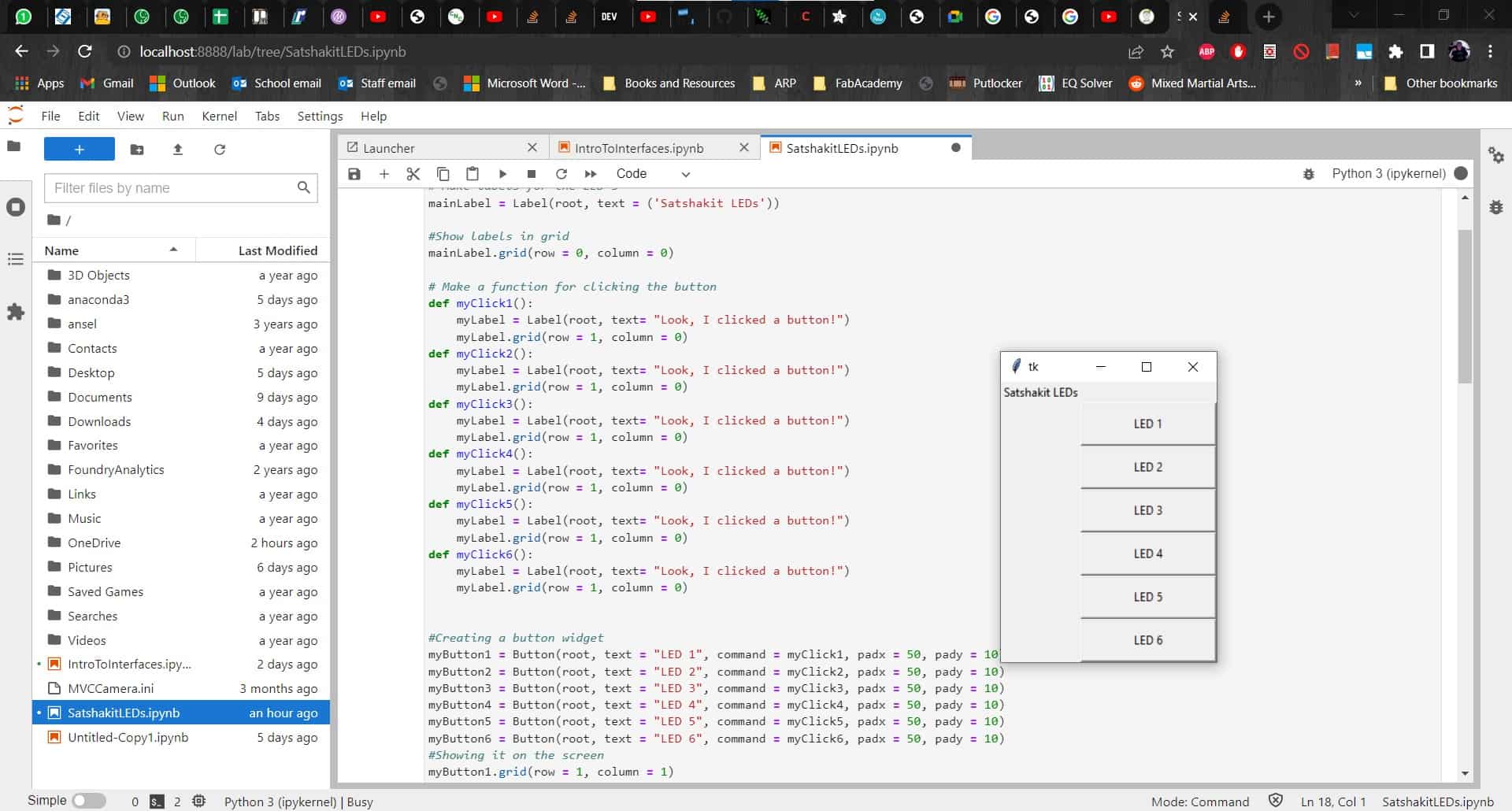
Button Functions
Eventually I decided to lose the labels altogether and to just use text on my buttons to serve the same purpose. For the button functions, I needed some way to separate the buttons in the code so they could do different things. Instead of each button sending only H or L, I decided to add a number to each corresponding to the LED I wanted to light up.
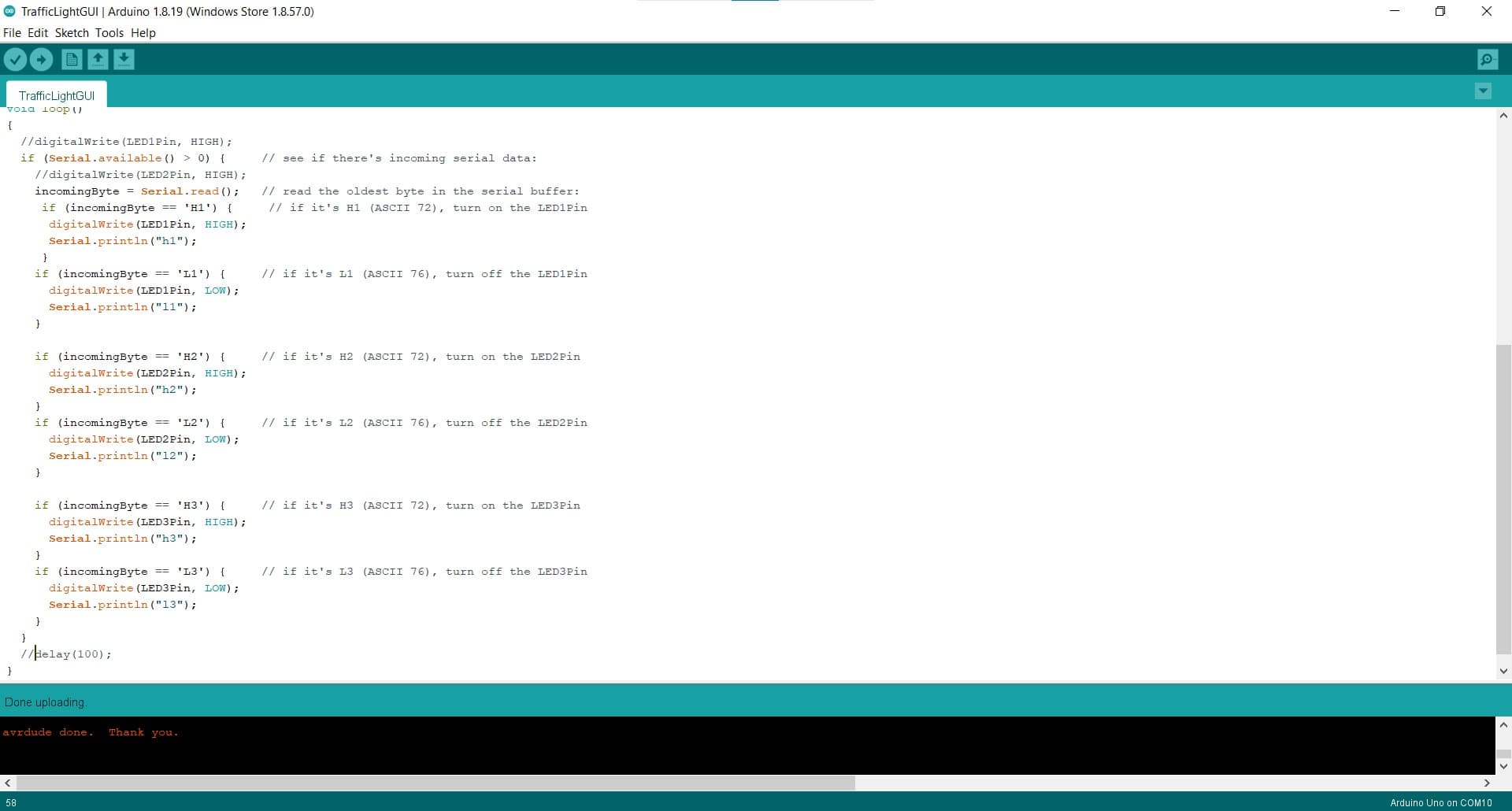
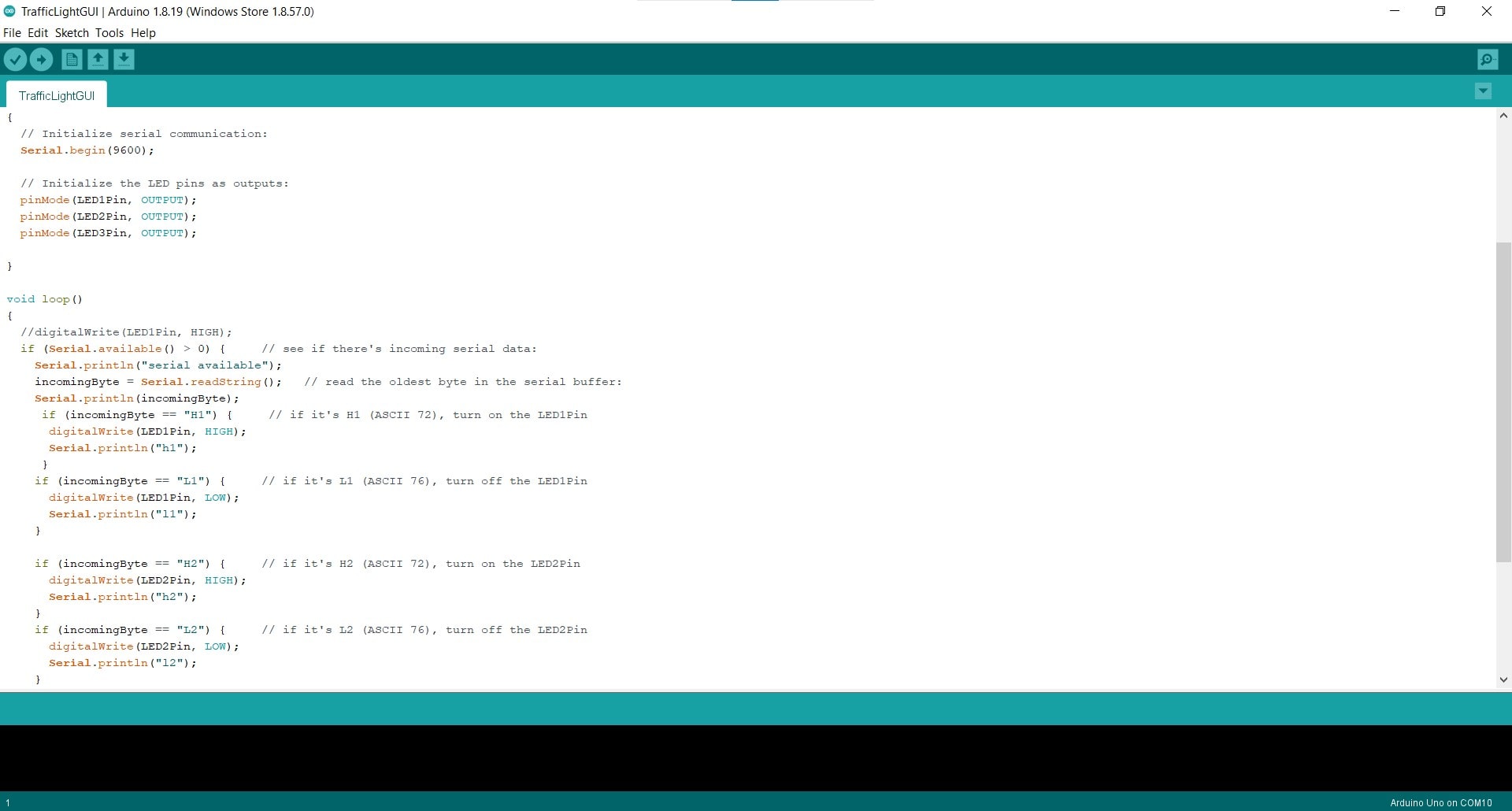
Expanding the Arduino Code
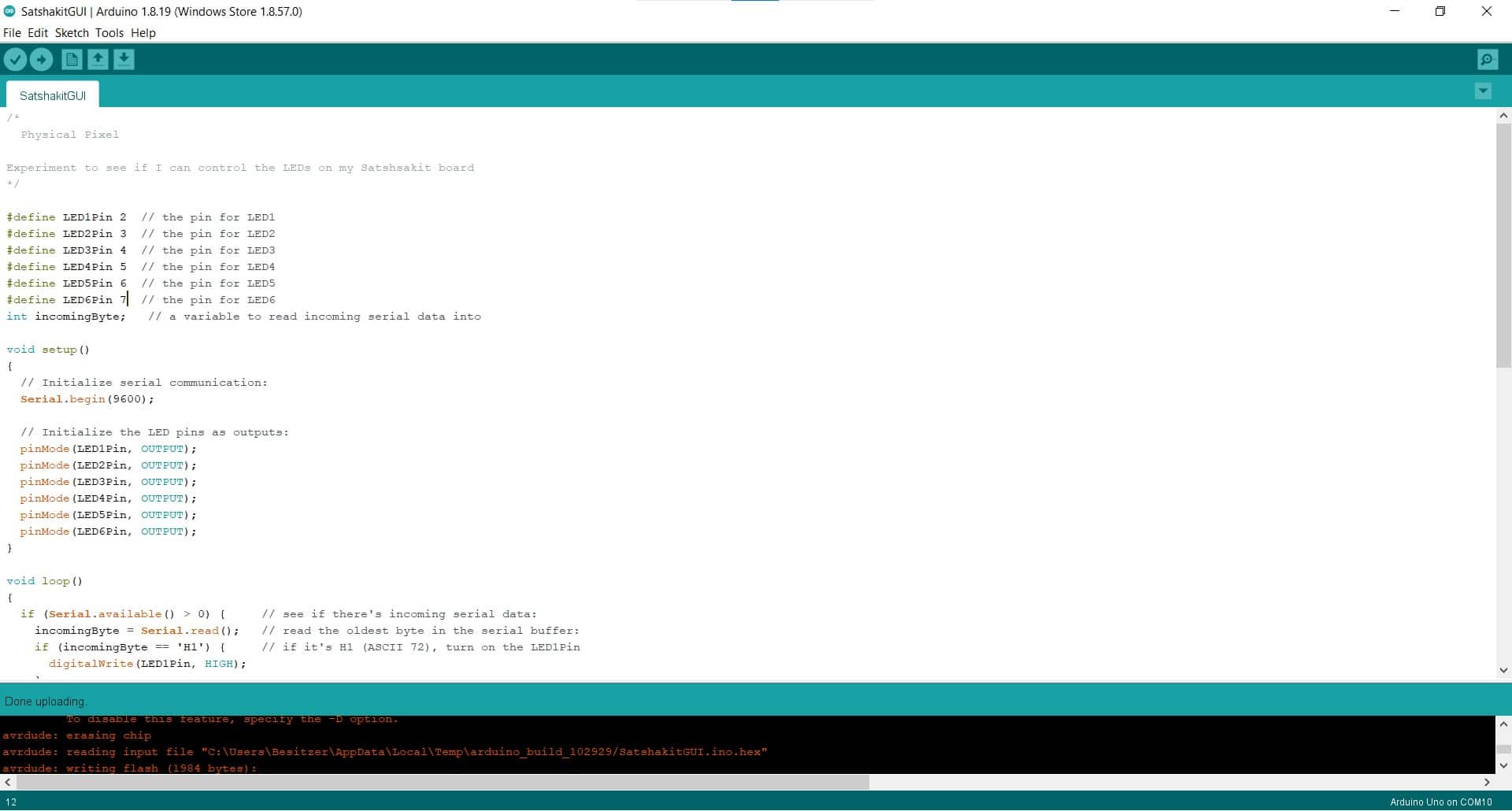
I also made similar changes in the Arduino code as well as expanding the program to activate all six LEDs, instead of only one.
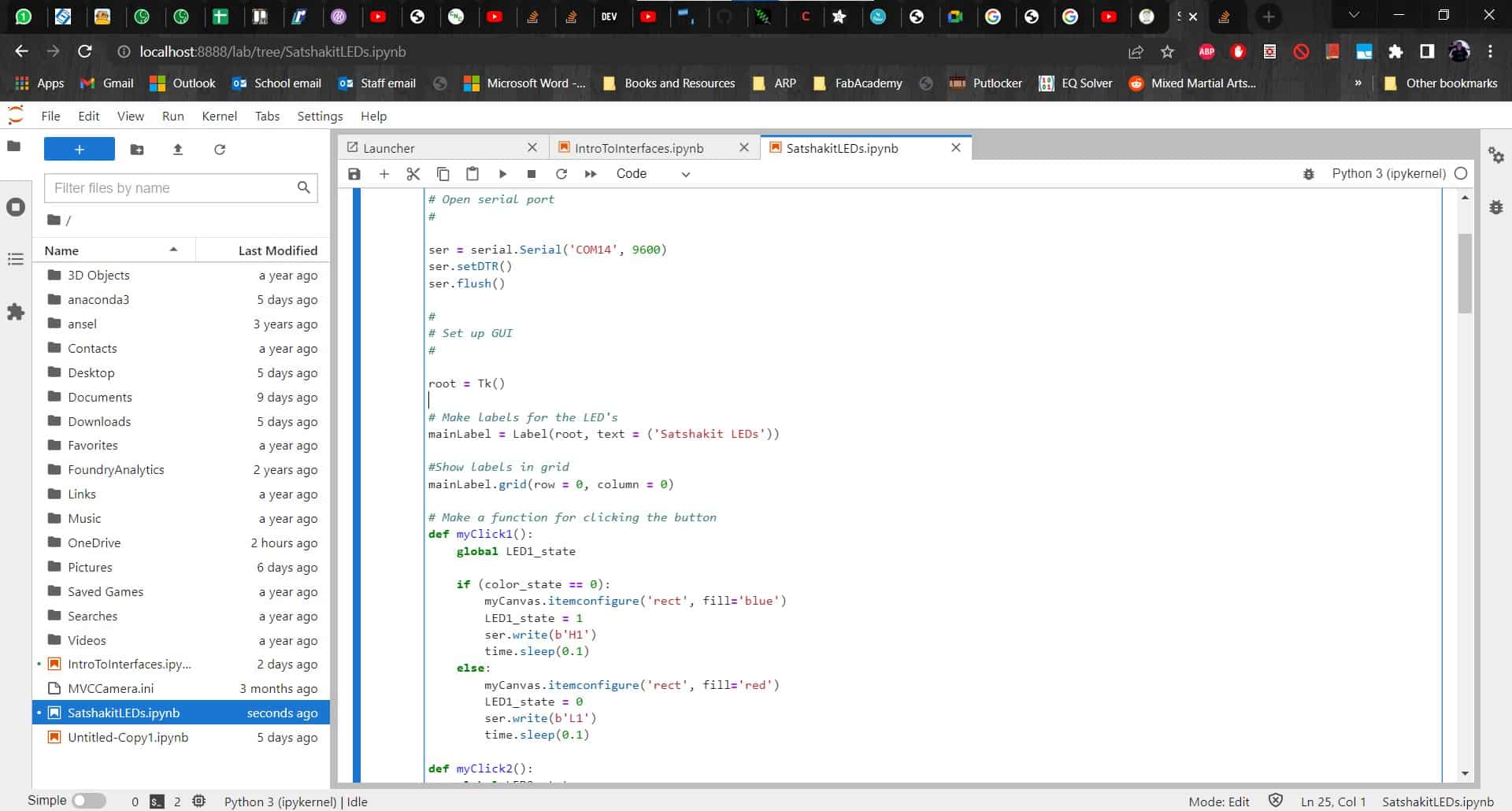
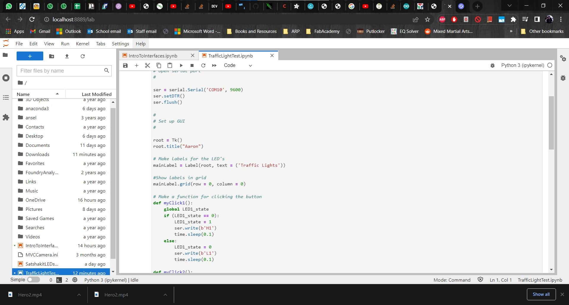
Click Functions
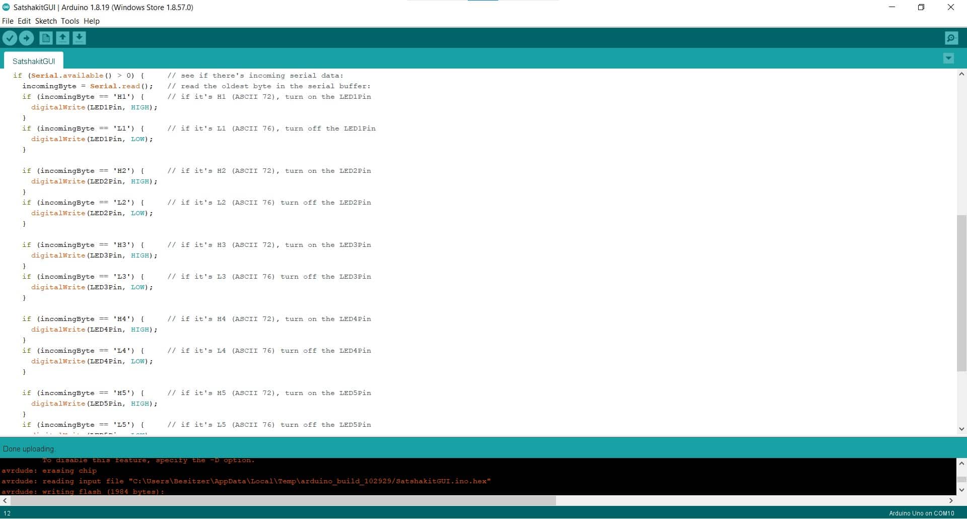
I kept the structure of the functions very simple to begin with. If serial data is available, the program reads that data into a variable and then compares that variable to the activation strings.
More Errors
Unfortunately, the code wasn't working. I kept getting errors no matter what I tried.
Adding Serial.println()
With Leen's help, I added some lines to the code to give myself some clues as to what was going wrong. I basically told it to print a message whenever it enters the loops, so I could see which loops were working and not working
String instead of Integer
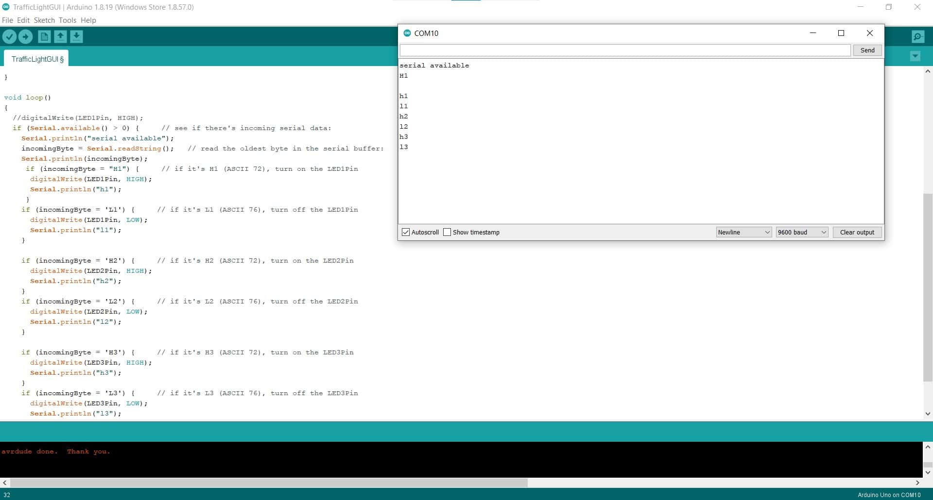
The first thing I had to fix was to make the incomingByte variable a string instead of an integer since I now wanted it to understand that H1 went together as a string instead of two separate inputs. Of course, this generated even more errors until I discovered I needed to use the Serial.readString() command since I had changed the type.
"Quotes" for Strings
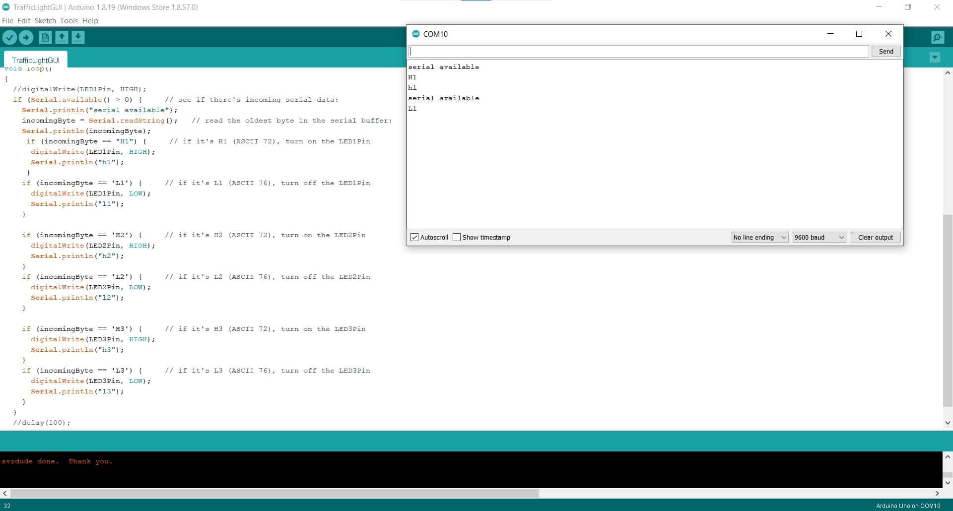
I also learned that I needed double quotes for the comparators instead of single quotes, since the syntax is different for strings. It took some time, but finally, the code for the Arduino was working.
I Shall Not Pass

I had solved all the little problems with my code, so I could finally learn about my biggest problem -- I had no way to communicate with my board directly via a serial connection. In the past, I was able to use the Arduino ISP to send serial data to my board, but now the serial port on the Arduino was busy listening for data from the GUI. To complete my mission for the week, I would need an FTDI cable...and we didn't have one in the lab...and it was already Tuesday evening.
New Plan
New Output Device
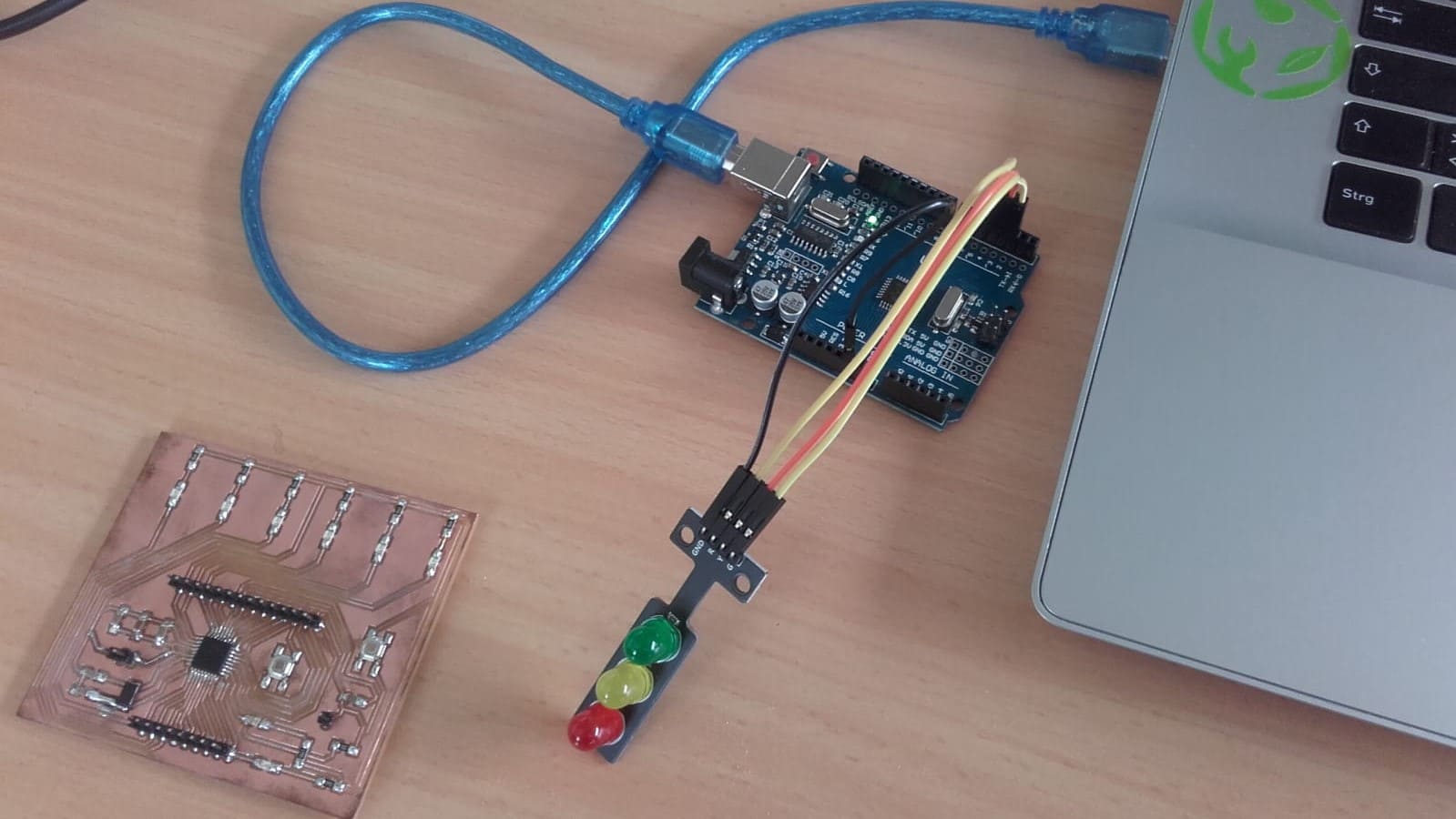
I wanted to be able to submit something for this week, so I went to the supply cabinet and grabbed a traffic light LED module.
Cutting the GUI in Half
Since I was already set up for six LEDs, I basically just had to cut all my code in half to make it work. I started with the GUI.
Same for the Uno Code
And then I repeated the bisection for the Arduino code.
Success
Finally, both programs were working and the output device was responding to my inputs from the GUI. It was really frustrating to not be able to make it work with my Satshakit, but I should be able to borrow an FTDI cable tomorrow and I will keep trying to make it work. In the meantime, it was satisfying just to see the lights coming on and off.
New Satshakit
OG Satshakit
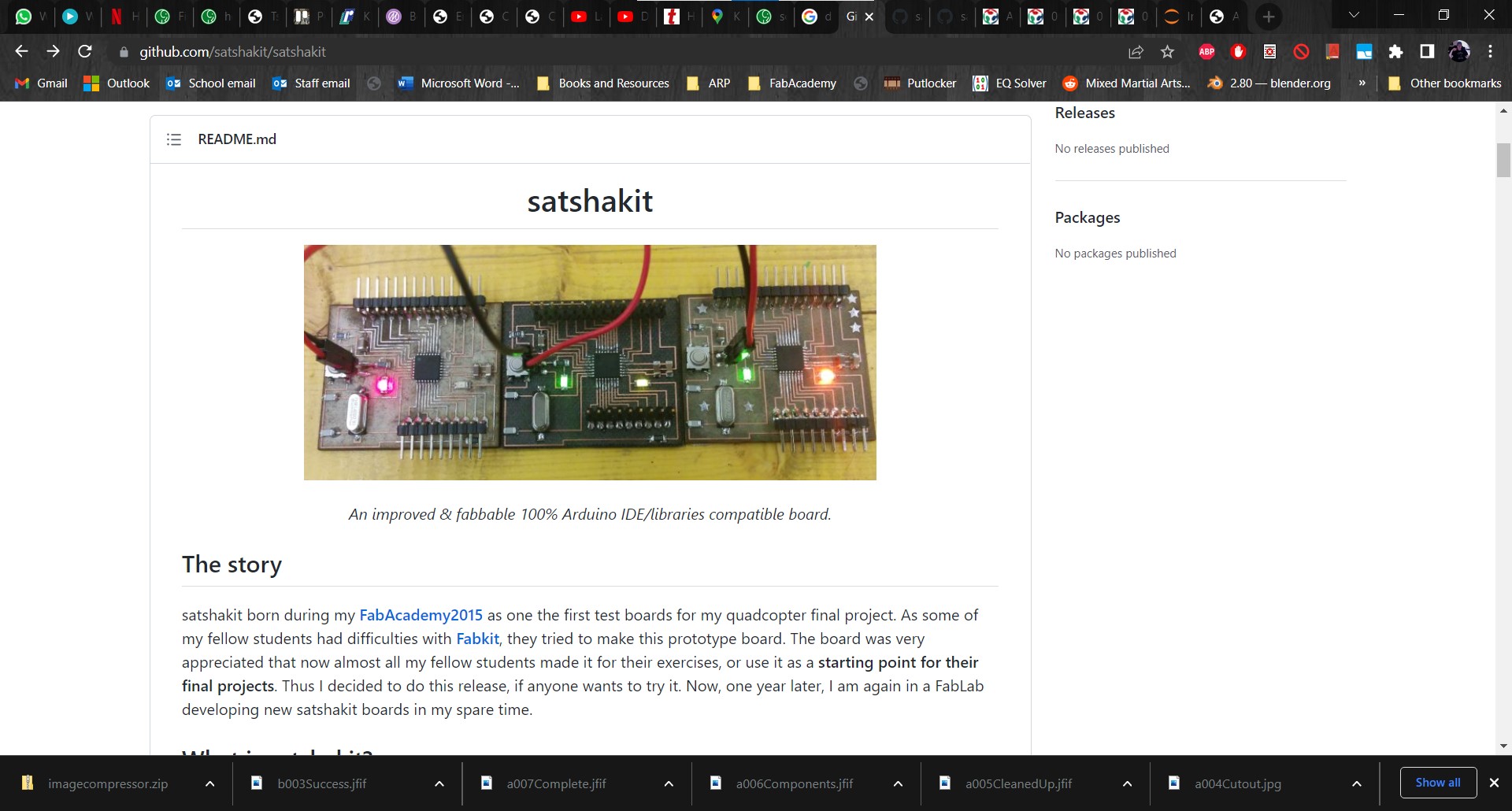
My Satshakit is now deep in the bowels of my final project and at this point, I don't want to pull it out of there for this assignment. So I decided to make another one. I don't need the extra button or LEDs this time so I just decided to build the original one as designed by Daniele Ingrassia.
Setting Up the Traces in MODS
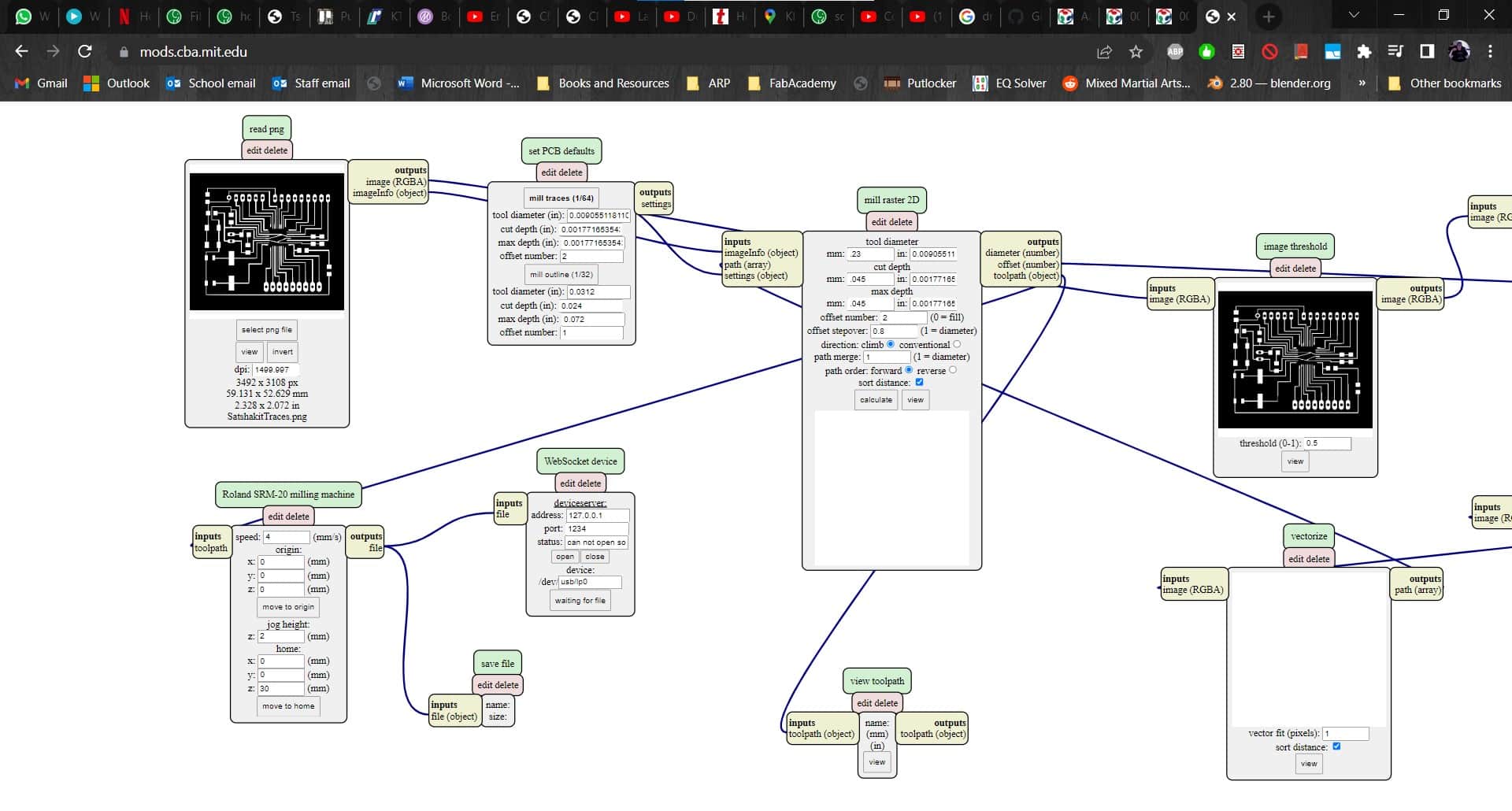
Using the png files from the Git Repo, I opened MODS and started changing the parameters. I wanted to cut the board on the Roland so I pulled up the appropriate server program and added a save module. Then I set the cutting parameters using the same values as I used for my FabISP programmer.
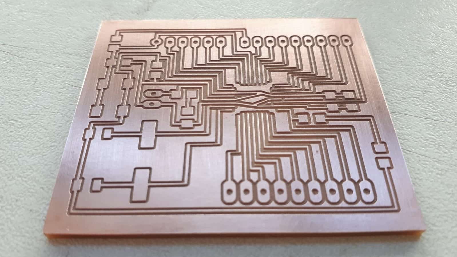
Cutting the Traces
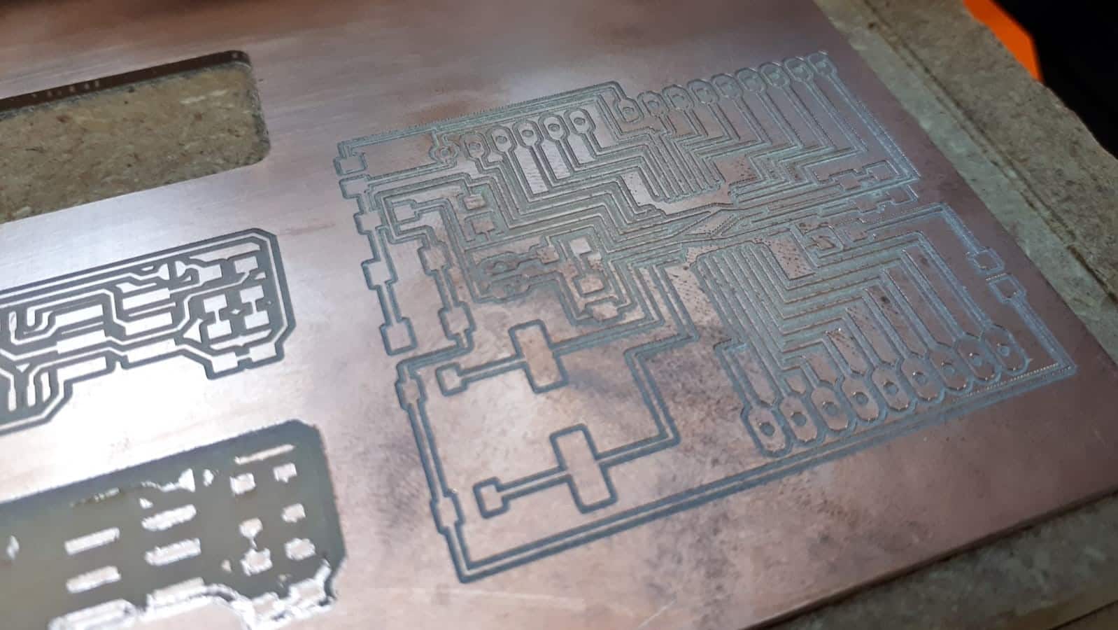
The traces came out great.
Setting Up the Cutout in MODS
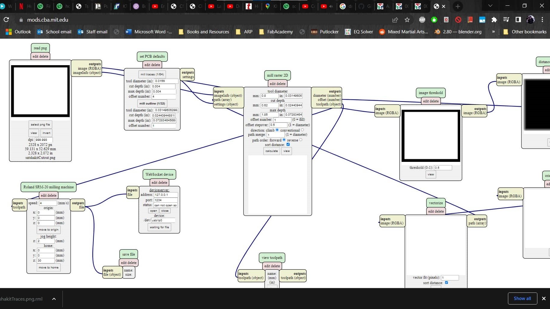
So I repeated the process with the cutout.
Cutout
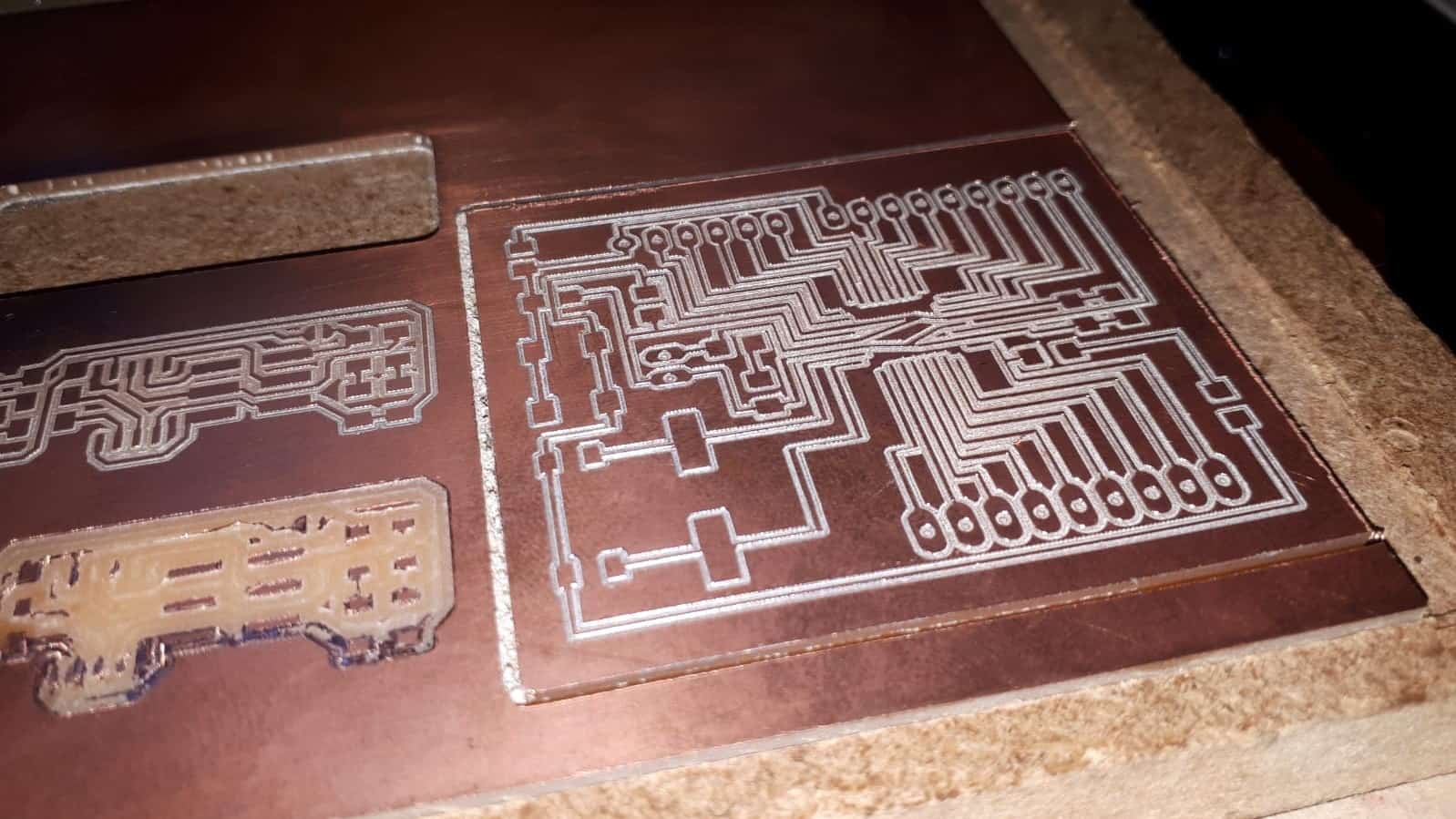
Which also came out with no problems.
Result
I was pleased with the result.
Components
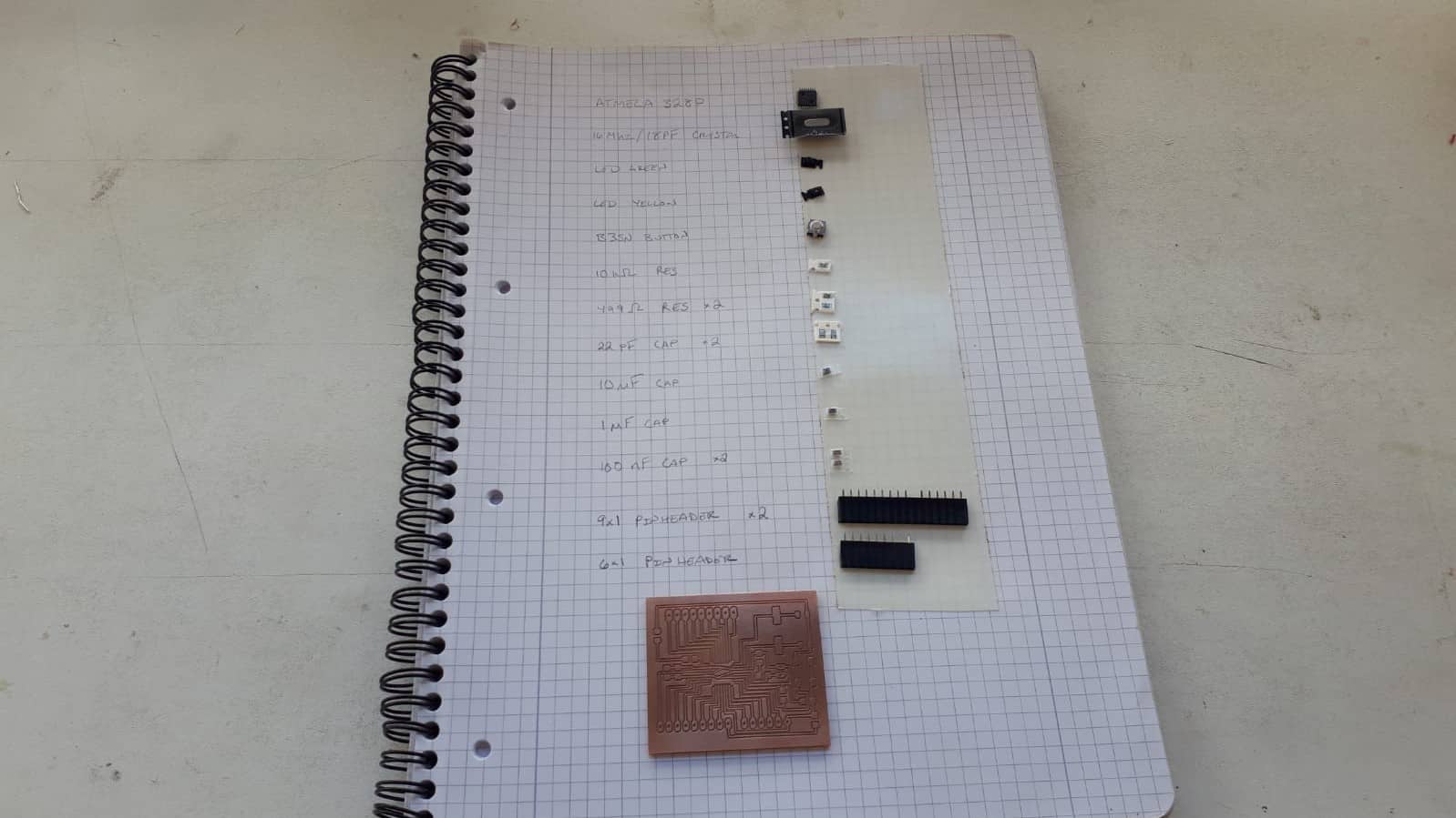
Next, I used the method I was taught to collect the components I would need to populate the board.
Finished
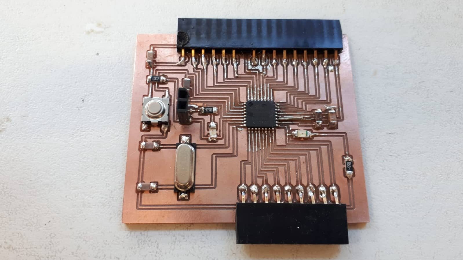
One of the traces got destroyed while soldering so I had to add another jumper, but the board came out pretty nice overall.
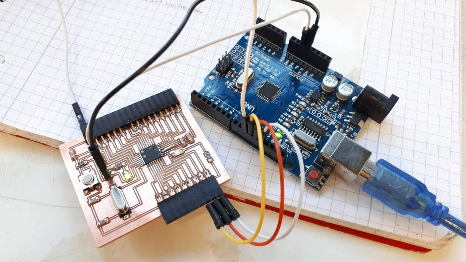
Arduino as ISP
For the sake of convenience, I used an Arduino Uno as an ISP programmer once again.
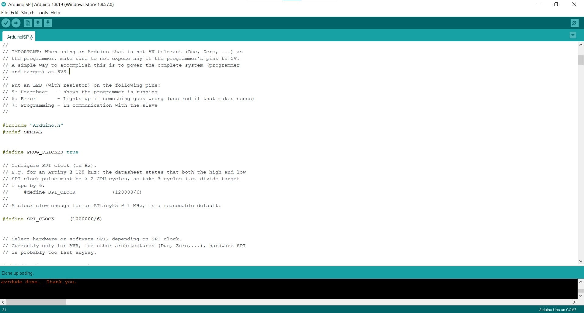
Uploading Example Sketch
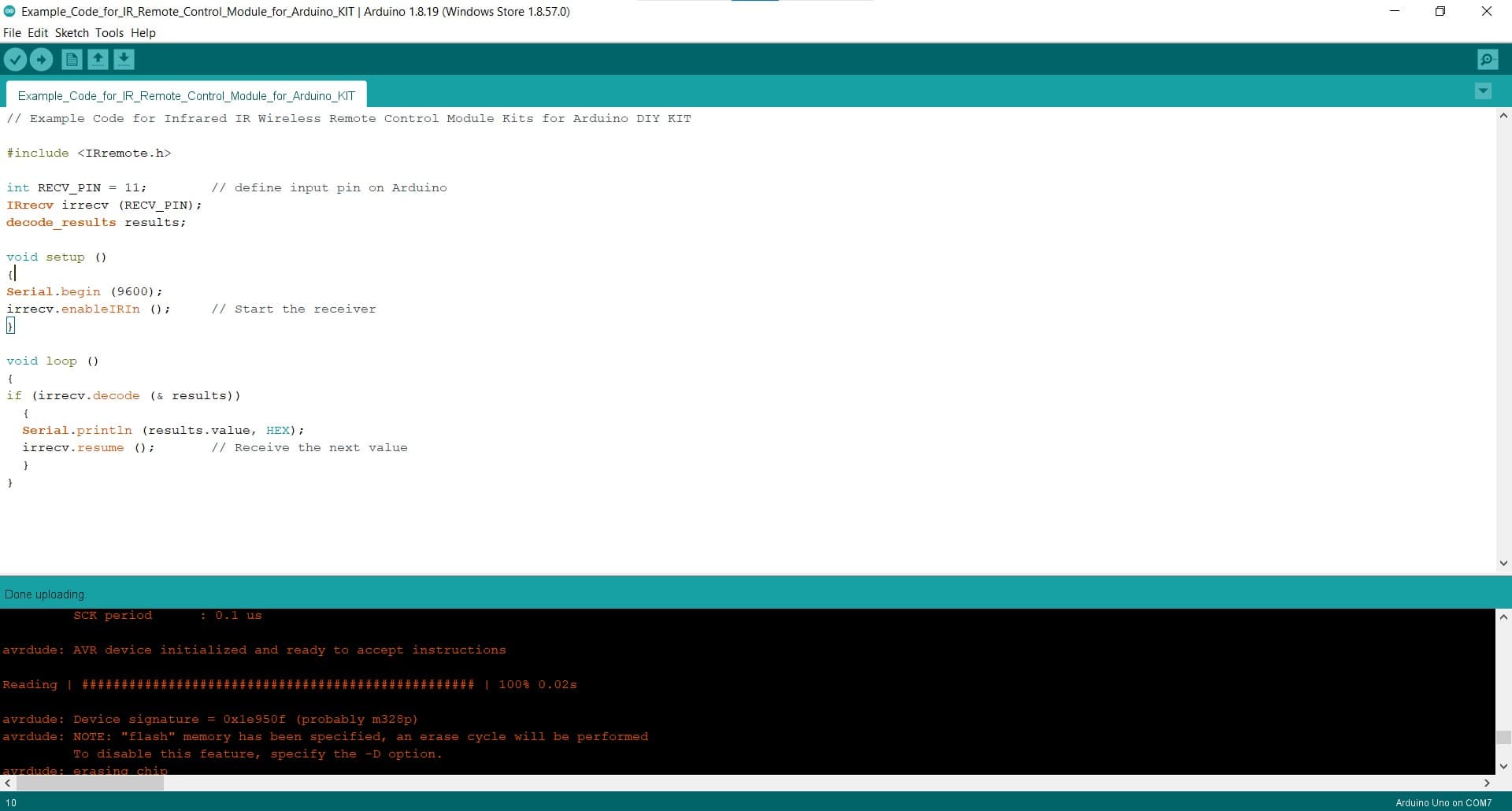
I had a little sketch up for a remote controller so I just decided to upload it to make sure the new board was working.
Success
The upload went without a hitch so I took that as evidence that my mission for the day had been successful and I went home.
Or so I Thought...
Unfortunately, that was the last (and only) bit of good news concerning that board. The next day, nothing worked the way it was supposed to. I did a lot of trouble shooting using my USBTinyISP programmer, using the Arduino as an ISP programmer and using an FTDI cable without a programmer. I even tested the chip and the crystal using an oscilloscope to make sure they were working properly. At first the crystal was not giving any reading in the oscilloscope so I replaced it on the board with a new one. The new one actually showed a voltage when powered so I was hopeful that my problems were solved, but in the end, everything was the same and the problems persisted. The main problem seems to be that there is some kind of a mismatch related to the device signature...but I don't really understand what that means and I'm not smart enough to make sense of the online help on this topic. It's just too far down the rabbit hole for me. So in the end, I decided to open up my final project after all. I wasn't very happy about it, but at least I knew that board worked, and I would only need to disconnect the pins that are necessary for the ISP and FTDI connections.
Never Mind the Rat's Nest
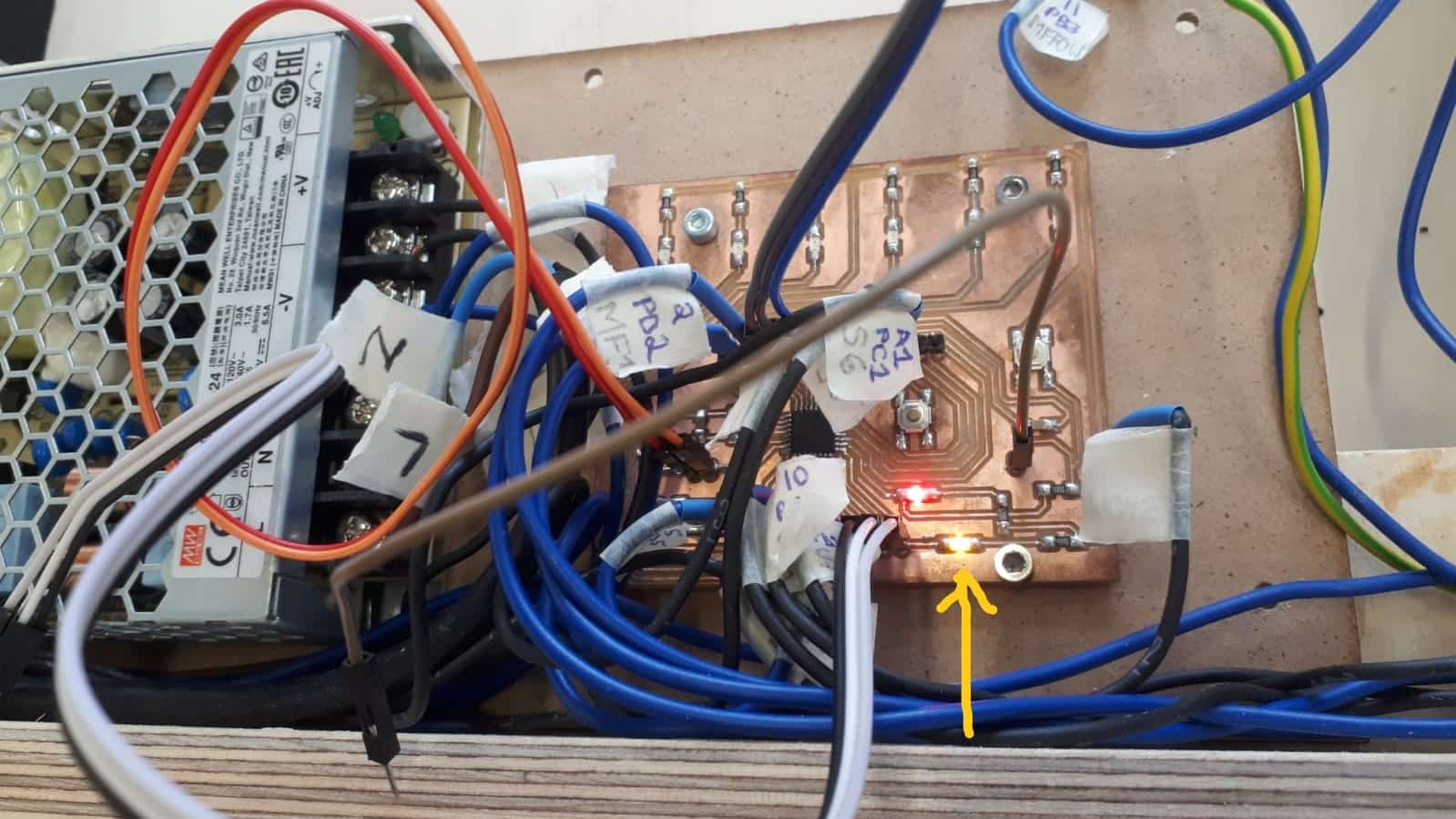
Most of the connections on the board are for the final project and can be ignored. I decided it would be enough to use the app I made to activate and deactivate the LED at pin 13.
Hero Video
Be sure to turn up the volume to here the narration. It's an ugly video, but it shows the application I made working to control a board I made. #AssignmentComplete