Input Devices
Hero Shots
Click Here for Our Group Assignment
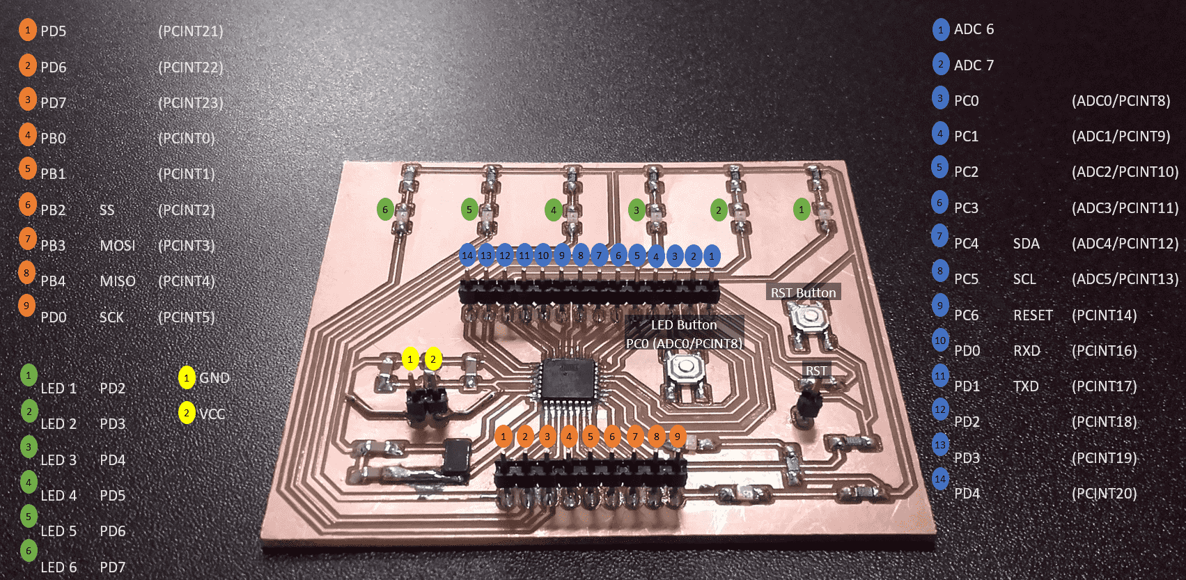
My World Map Circuit
Initial Reaction
Surprisingly, I am feeling ok about this week. I thought I would be lost, but I actually have a bit of experience with a few input devices so I wasn't as confused as I expected. Neil briefly discussed several input options as well as showing us numerous examples of the different options in action and how they can be used to serve various functions. The assignment this week is to add some input device to a circuit board that we made. We also have a group assignment to play with some input device and see the output. The group assignment sounds easy enough...and I am hoping the work I have been doing on my final project will pay off this week.
After Local Workshop
Once again, the local workshop was short, but informative. Marcello gave us a brief walkthrough of I2C and how you can use very humble microcontrollers to control relatively extensive arrays of sensors using the SDA and SCL lines. Then he showed us how to implement several of the basic sensors using Python. I still have to build my circuit for my final project so technically I think I could get away with using the buttons I have already chosen as my input devices for this week's assignment, but I would like to play with some of those ultrasonic proximity sensors so you could turn on the map just by gesturing near it. I am hoping to have my electronics for my final project finished or nearly finished by the end of this week.
Adding New Inputs to My Final Project
Playing With Ultrasonic Sensors
New Plan
As usual with these electronics assignments, I started by reading. We have a bunch of HC-SR04's in the lab, so I found the datasheet and started learning about how they work. While learning and thinking about the sensors, I decided to change the plan for the inputs of my final project. I was originally planning to operate everything with buttons, but since coming up with that plan, I have been nervous about having to push buttons on the side of the map, causing the whole thing to rotate on the wall. So, I have decided to replace those pushbuttons with ultrasonic sensors. With this new plan, now the whole map and/or the individual panels will be able to be activated by simply waving a hand in front of them. While reading the datasheet, I got nervous about my new plan since it looked like each sensor needed two pins on the microcontroller. However, with a bit more investigating, I found this very handy guide that described the possibilities and recommended the NewPing library for the Arduino IDE. Supposedly, this would allow me to control arrays of sensors using only one input pin for each.
Installing NewPing Library
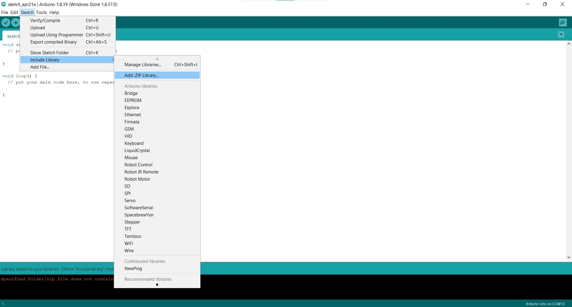
So I downloaded the NewPing library and then installed it in the Arduino IDE using the Add Zip Library tool in the Sketch menu.
Changing the Programmer
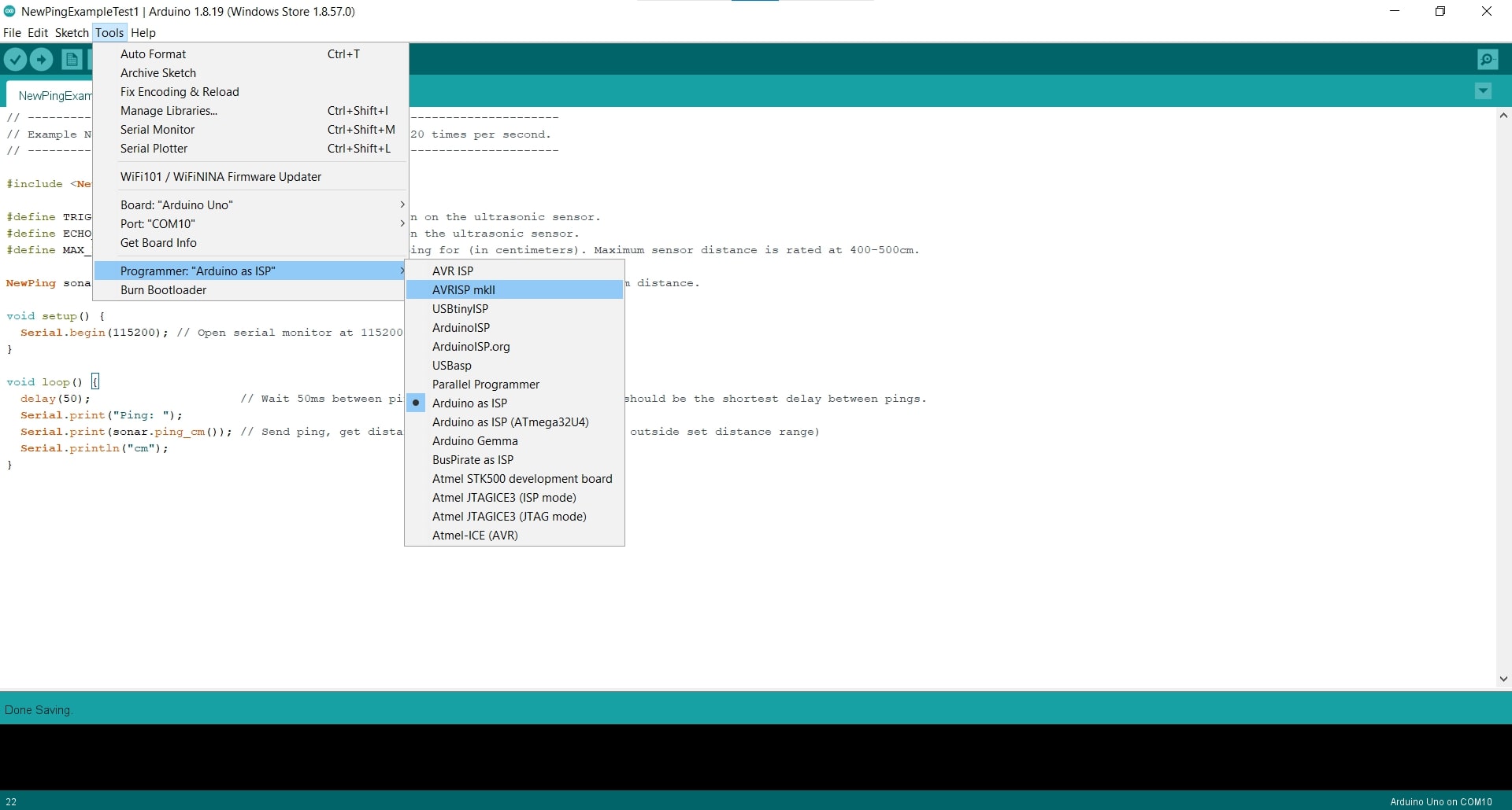
Next, in the Tools menu, I changed the programmer to the AVRISP mkii. I was really curious if I could use this wiring diagram for the ultrasonic sensors so I figured I would begin by trying to get a single sensor working with an Arduino Uno.
Combining Signals
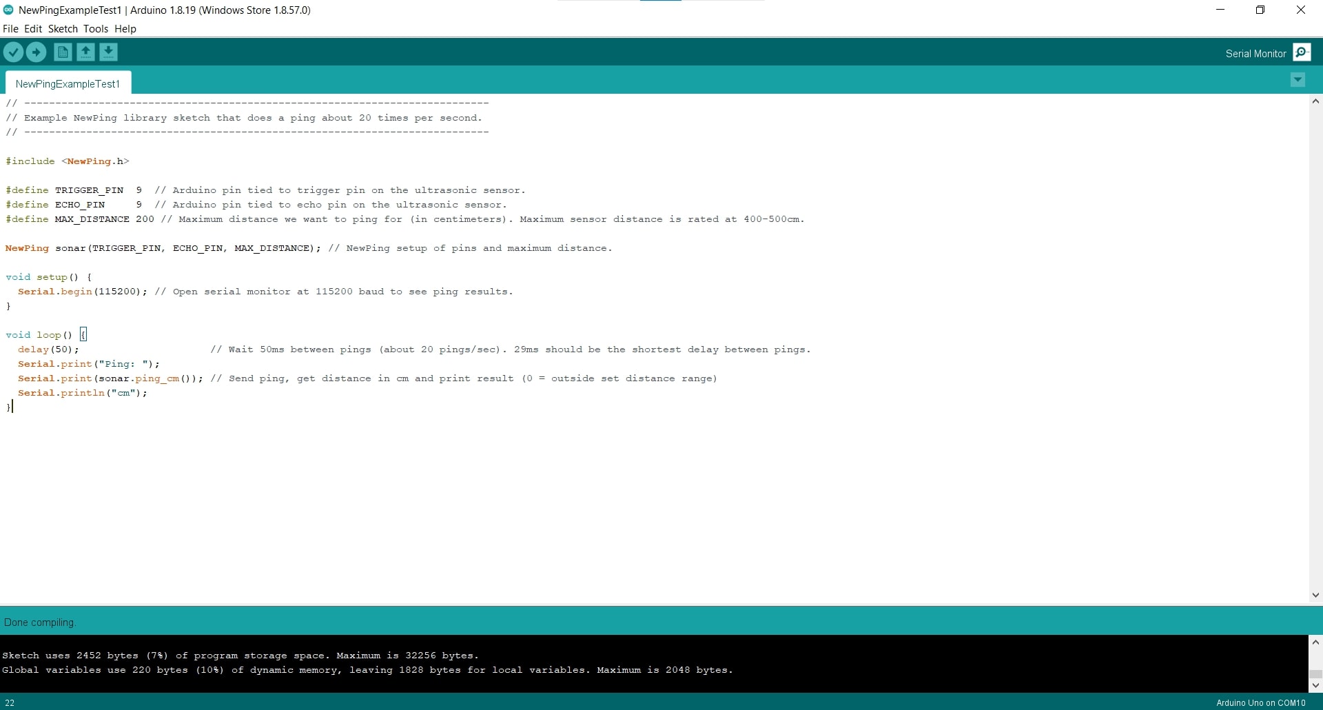
If successful, then I would try multiple sensors in an array, and if that works, then I will program them to run on my Satshakit, instead of the Arduino. For the first spiral, I simply changed the example code so both the trigger pin and the echo pin would connect to the same pin on the Arduino.
Baud Rate
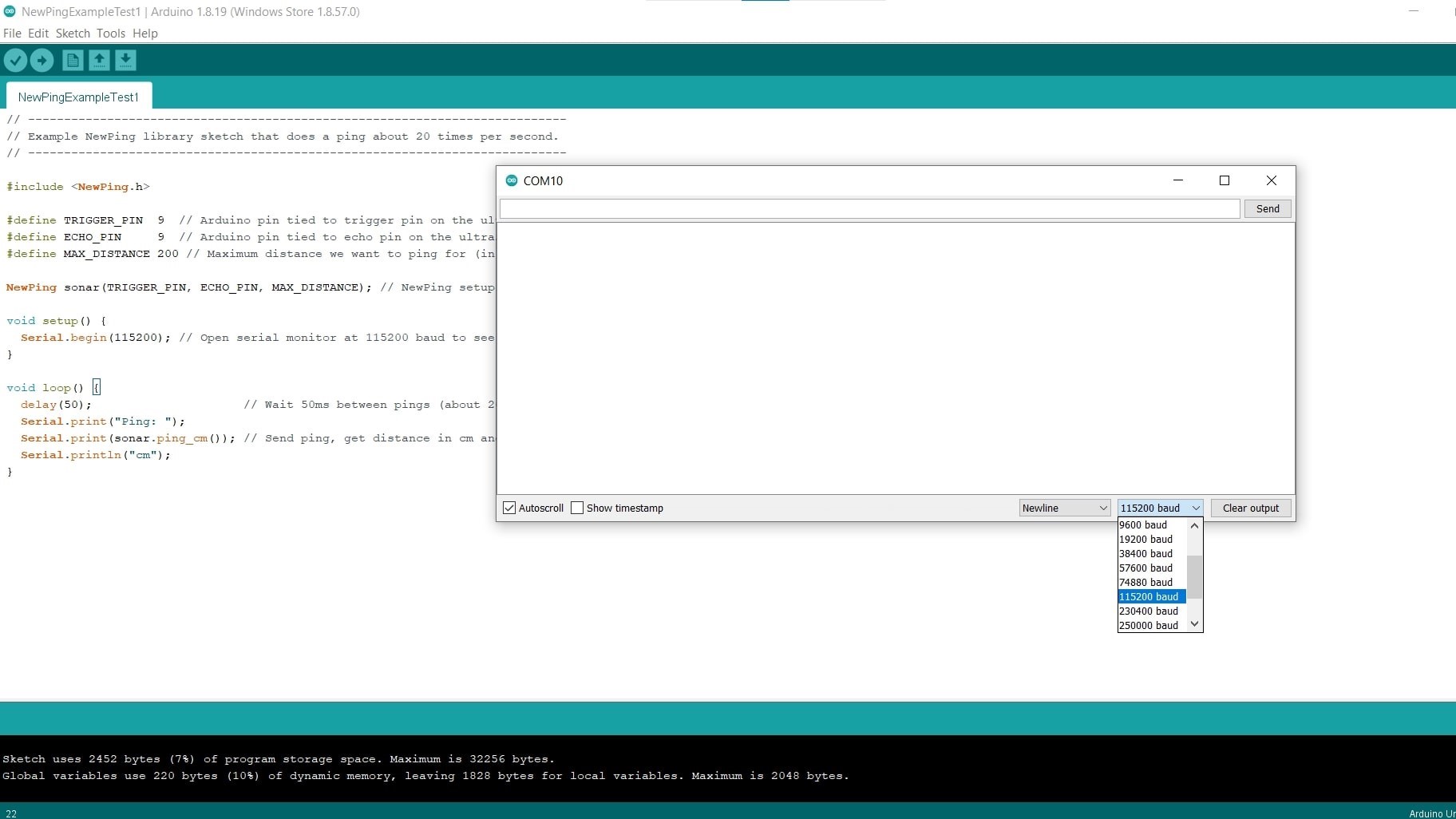
Then I changed the baud rate in the Serial Monitor to match that of the sensor.
Physical Connections
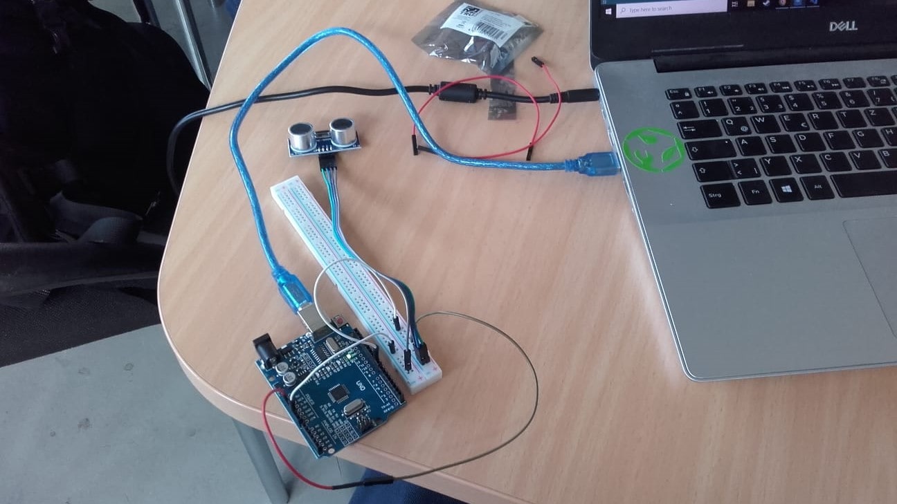
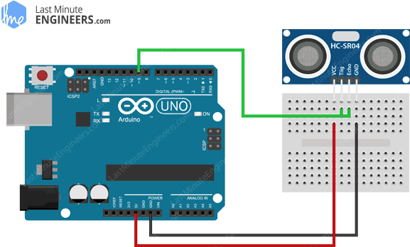
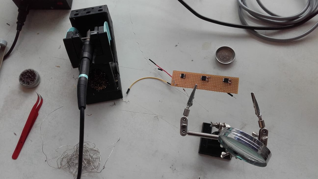
And hooked up the physical components to the Arduino using the only breadboard I could find, and then to my laptop.
First Try
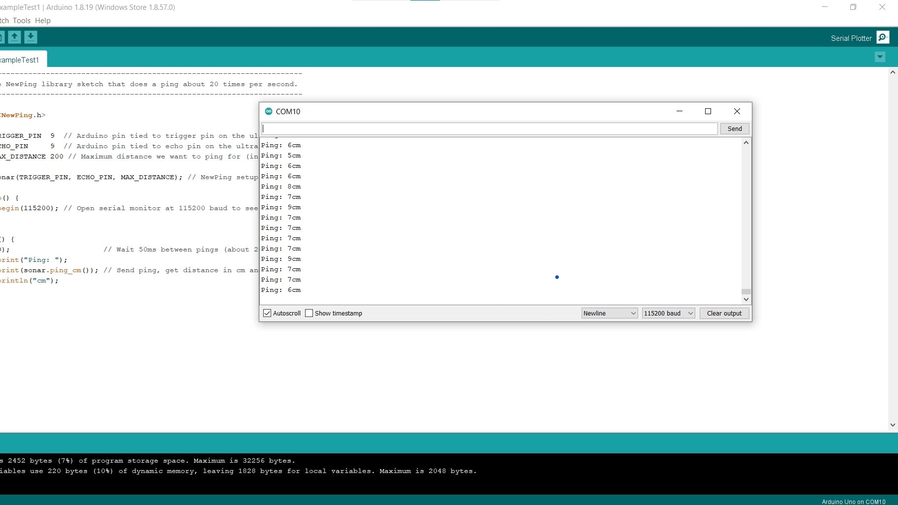
Then I compiled and uploaded the sketch and amazingly, it worked the first time. I could hover my hand over the sensor and get real time feedback in the Serial Monitor. Awesome!
More Sensors!
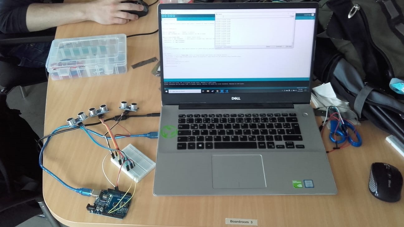
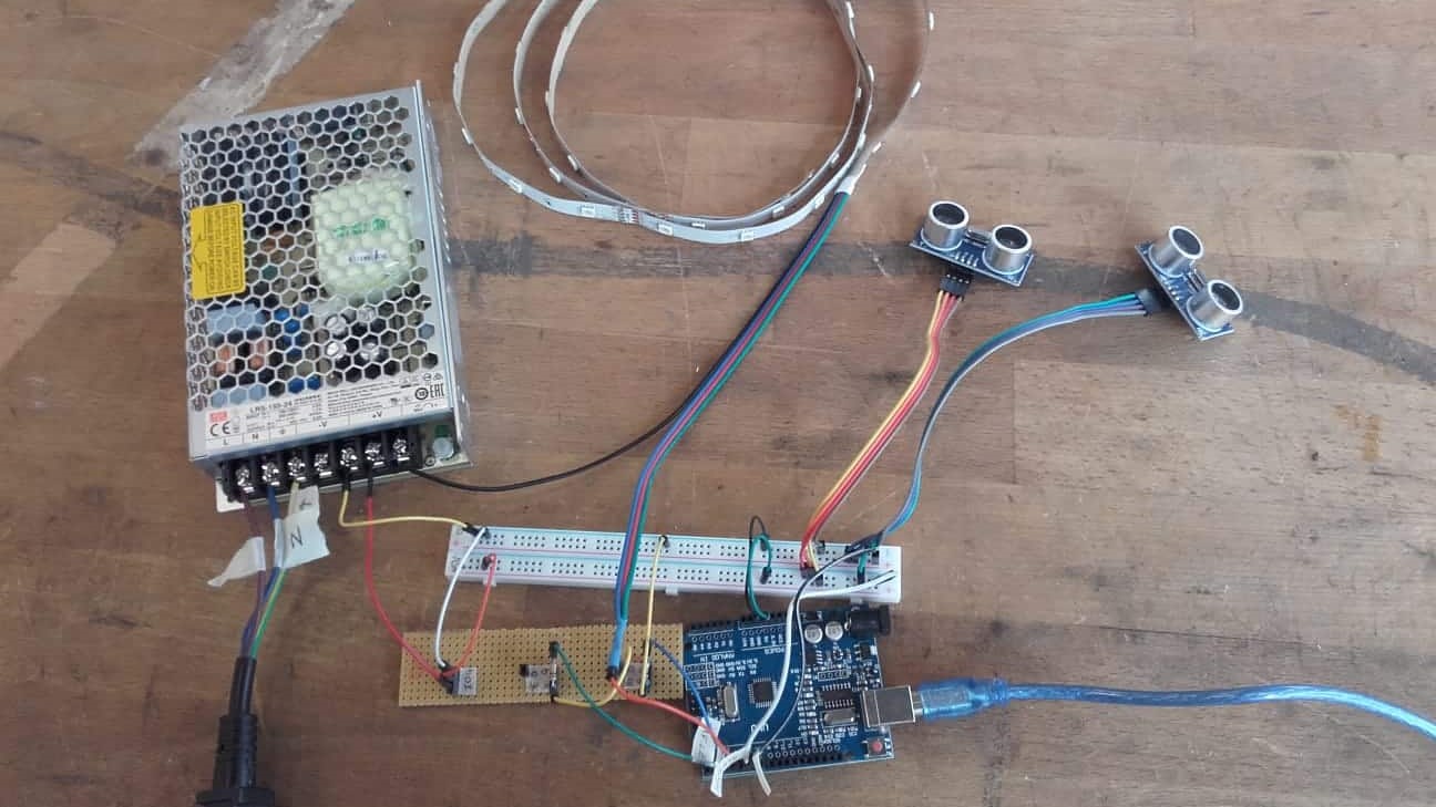
If a little bit is good, then a lot must be great, right? Riding the waves of my success with a single sensor, I got busy connecting multiples. In the end, I will need six or seven sensors, but I figured 3 was reasonable for proof of concept.
Success
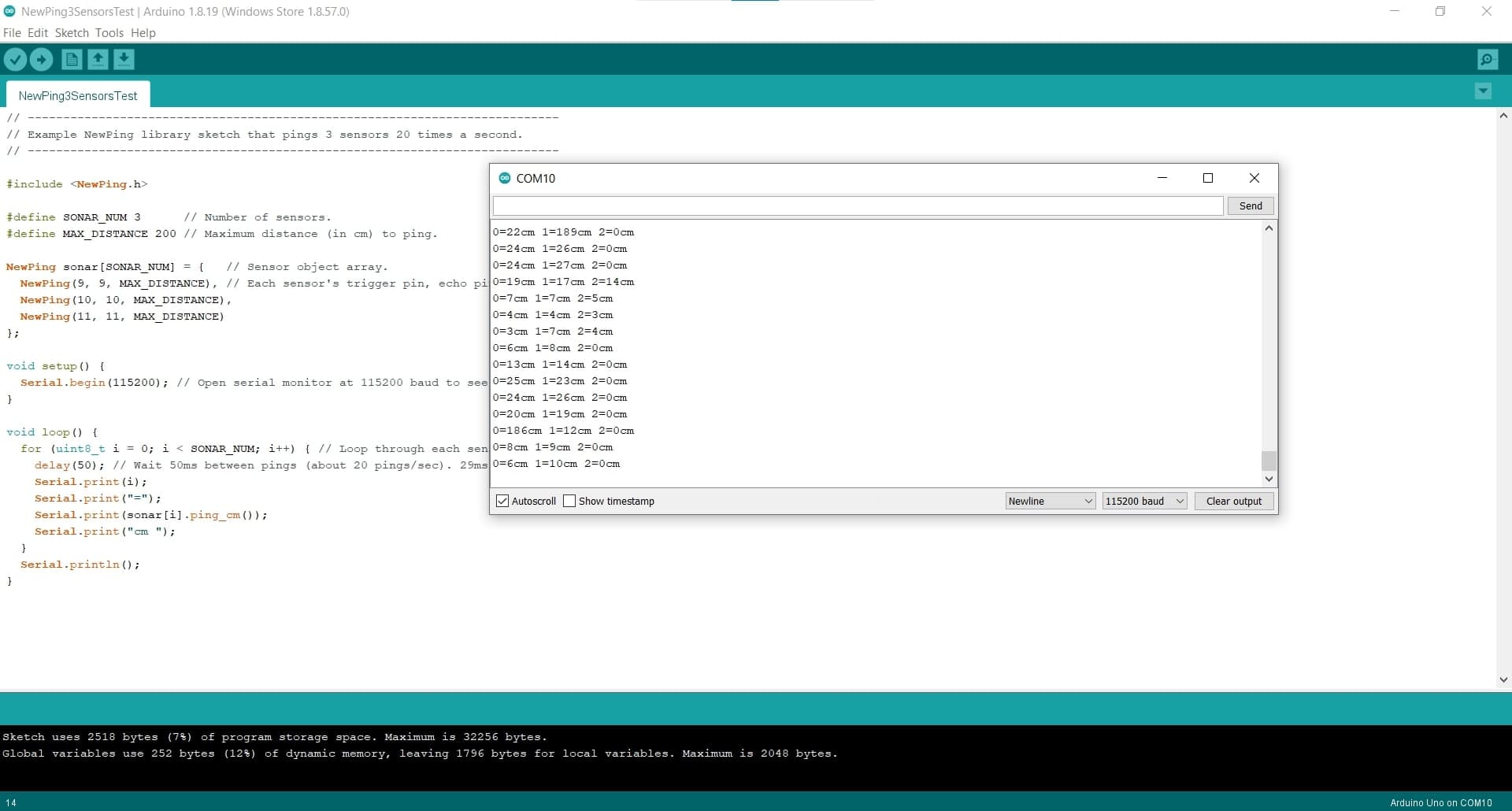
Once again, I simply changed the example code for multiple sensors to be only one Arduino pin each, instead of two., and then compiled and uploaded the sketch once more. And it worked again! It is so satisfying when these things actually work.
Now for My Project
Creating the Full Circuit
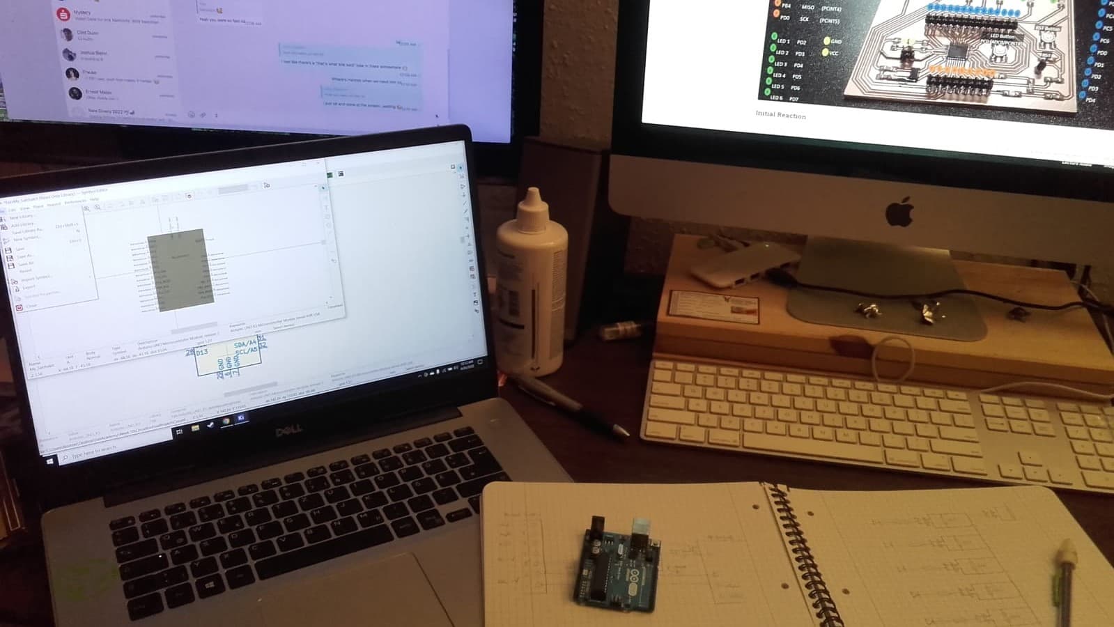
I started with my default, pencil and paper and worked out all of the logic for the full circuit including the power supply and the Satshakit. Then I used my pinout and the datasheets for all my components to create the circuit in KiCAD.
Schematic for Full Circuit
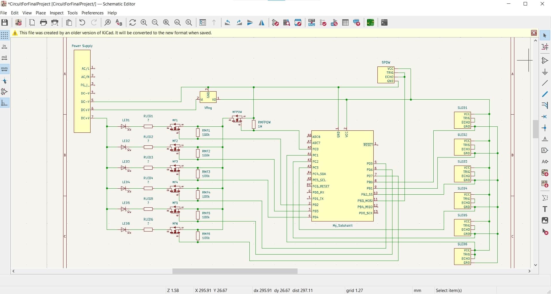
I had to use the Symbol Editor tool to create my Satshakit,voltage regulator and power supply, but that was pretty intuitive. I would love to have my work double checked by an expert, but those are in short supply at the moment so I am going to make a test first.
Soldering for Test
I decided to test one branch of my circuit, before coding and wiring for all six branches. So I soldered my voltage regulator and two MOSFETs to a breadboard.
Connecting all the Components
Then I connected everything up according to my schematic. This took a bit more creative soldering of jumper wires, but everything is now hooked up and labeled.
Programming
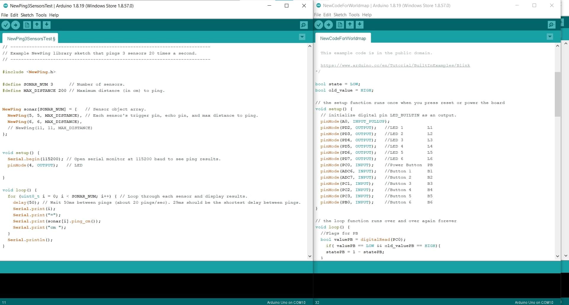
I got into the Arduino IDE and started by trying to combine the code I created for the buttons, with the code from the NewPing example for three sensors.
Coding as a Non-native Speaker 😬
Everything went so well up until this point lol. I don't know why I am so bad at programming, but this is where I ran into the wall. I used a guide for interfacing the ultrasonic sensors with an Arduino Uno, and I used another guide for controlling the LED strips. I only have enough pins to make white light (RGB all on simultaneously), so I don't need to worry about controlling the colors individually; and I don't care about dimming since I will set the brightness statically in the hardware using resistors. Unfortunately I couldn't figure out how to isolate the signals from the individual sensors to activate the pins for the MOSFETs that energize the LEDs. I also couldn't figure out how to isolate the sensor that will act as the main power button. Not sure if I mentioned it, but I suck at programming and dealing with arrays isn't my thing. Toward the end of the day on Tuesday, I discovered a thread that gave me some clues, but I was out of time to put them into action. I will try some more tomorrow before class, but unfortunately I won't have time to test it with the hardware.
Testing the Circuit
Success!
I finally got the full circuit for the world map working correctly with the input and output devices. This has been fully documented, including the code, during my Output Devices Week, so I will not be redundant here. The board is working; the circuit is working; the code is working; and all of the other peripherals and hardware are working as well. I am very happy.